
Abstract
In order to improve the trajectory tracking control effect of mobile robot, a mobile robot trajectory tracking control (TRC) method based on AVRX operating system is proposed. The principle of AVRX operating system is analyzed and the hardware structure of mobile robot is designed. The input-output relationship of mobile robot trajectory is determined according to multivariable fuzzy controller and the wrong data of mobile robot trajectory tracking information is eliminated by radar point cloud measurement. The TRC model of mobile robot is designed through Euler Lagrange equation to realize the TRC of mobile robot. The experimental results show that the trajectory tracking accuracy of mobile robot is as high as 97.9%, the trajectory tracking time is 16.2 s, and the trajectory tracking error of mobile robot is only 0.04. It shows that the TRC effect of mobile robot is improved, which provides a reference for the trajectory tracking control of mobile robots.
Keywords
Introduction
At present, wheeled mobile robots are widely applied in the fields of automobile production, national security and space exploration, etc. [1, 2, 3]. The path tracking of mobile robot has become one of the hotspots of current research. Path tracking refers to setting an initial state of the mobile robot. The mobile robot starts from the known state and follows its ideal path. The initial point of the mobile robot has no fixed requirements. In the field of mobile robot research, this is undoubtedly a basic but important problem [4, 5]. When the wheeled mobile robot performs path tracking in the external environment, it will produce errors caused by its own unstable structure and other interference factors. To solve this problem, a variety of path tracking methods have been born to ensure that the robot can better complete the path tracking task [6]. Relevant scholars have studied this and made some progress.
Han et al. [7] proposed a TRC method of cooperative robot based on Udwadia kalaba theory, used nonholonomic constraints to impose nonideal constraints on the cooperative robot system, analyzed the influence of uncertain factors, constructed an adaptive law, designs a controller to maintain the system stability, and realized the TRC of cooperative robot through Udwadia kalaba theory. However, the tracking process of this method is complex and time-consuming. Han and Liu [8] proposed a trajectory error optimization method of industrial robot based on B-spline curve, used hybrid algorithm to optimize the trajectory of industrial robot, and simulated and verified the tracking error. The three-dimensional model diagram of industrial robot is established. The angular displacement motion equation of each joint is derived according to the D-H method and the trigonometric function relationship. The motion trajectory of industrial robot is designed by using B-spline curve. The particle swarm optimization algorithm is introduced and improved, the hybrid algorithm is designed and the B-spline curve is optimized, and the optimization iteration curve of hybrid algorithm is given. MATLAB software is used to simulate the tracking error of joint angular displacement of industrial robot. However, this method taking long time in tracking time. Xiao et al. [9] proposed the dual loop TRC method of wheeled robot based on sliding mode variable structure. This method can improve the accuracy of robot dual loop trajectory tracking, but the pose tracking stability is poor.
To solve the above problems, a TRC method of mobile robot based on AVRX operating system is proposed in this paper. Firstly, the hardware structure of the mobile robot is designed based on the principle of ARVX operating system. Secondly, the input-output relationship of the trajectory of the mobile robot is determined according to the multivariable fuzzy controller. Then, the error data of the trajectory tracking information of the mobile robot is eliminated by point cloud measurement. Finally, the TRC model of the mobile robot is designed by using Euler Lagrange equation to realize the TRC of the mobile robot. The TRC effect of the proposed method is verified by experiments, which provides a reference for the trajectory tracking control of mobile robots.
Hardware structure design of mobile robot
AVRX is a lightweight real-time operating system based on AVR Series MCU. It fully supports preemptive and priority driven task scheduling algorithm. AVRX kernel is completely written in assembly language. When using it, first compile it into a link library corresponding to the target device, and then link it with the application to generate the final executable code [10, 11, 12, 13]. The use of static link library can make the functions unused by the kernel not occupy the program storage space. Generally, the space occupied by AVRX kernel is 1000–1400 bytes. AVRX is a free open source operating system. The current version is AVRX2.6F, the source code can be downloaded from the AVRX official website. The version of AvrStudio used is AvrStudio 4.18.684. Some configurations are required to use AVRX. Users only need to customize some practical tasks according to the actual needs to complete the design of the system [14]. AVRX is a special real-time operating system for AVR processor, so when applying AVRX operating system on AVR processor, the designer does not need to consider the problem of transplantation, and can easily use C language to call the service function provided by the operating system for programming.
Based on AVRX operating system, the overall system of the omnidirectional mobile robot is shown in Fig. 1. The system is composed of ROS system layer, embedded system layer and execution and sensing device layer, respectively. The ROS system layer takes the target point as a reference and outputs the motion trajectory of the omni-directional mobile robot through the map and positioning information. The embedded system layer sends the drive control command to the device layer according to the control command issued by the upper layer, receives the sensor data information sent by the device layer, and fuses it to realize the autonomous positioning of omni-directional mobile robot [15]. The execution and sensor equipment layer mainly includes encoder, lidar, inertial measurement unit and motor execution unit, which is mainly responsible for executing relevant actions and collecting data information according to the received instructions.
Structure diagram of mobile robot system.
The overall hardware structure of the omni-directional mobile robot takes the PC system and the bottom stm32f407 control board as the core, while the mileage measurement unit, inertial measurement unit and drive control unit are composed of various actuators and sensors, as shown in Fig. 2. In addition, the lidar will upload the environmental map scanning data to the ROS system, which is responsible for the functions of positioning and navigation.
Hardware structure of mobile robot system.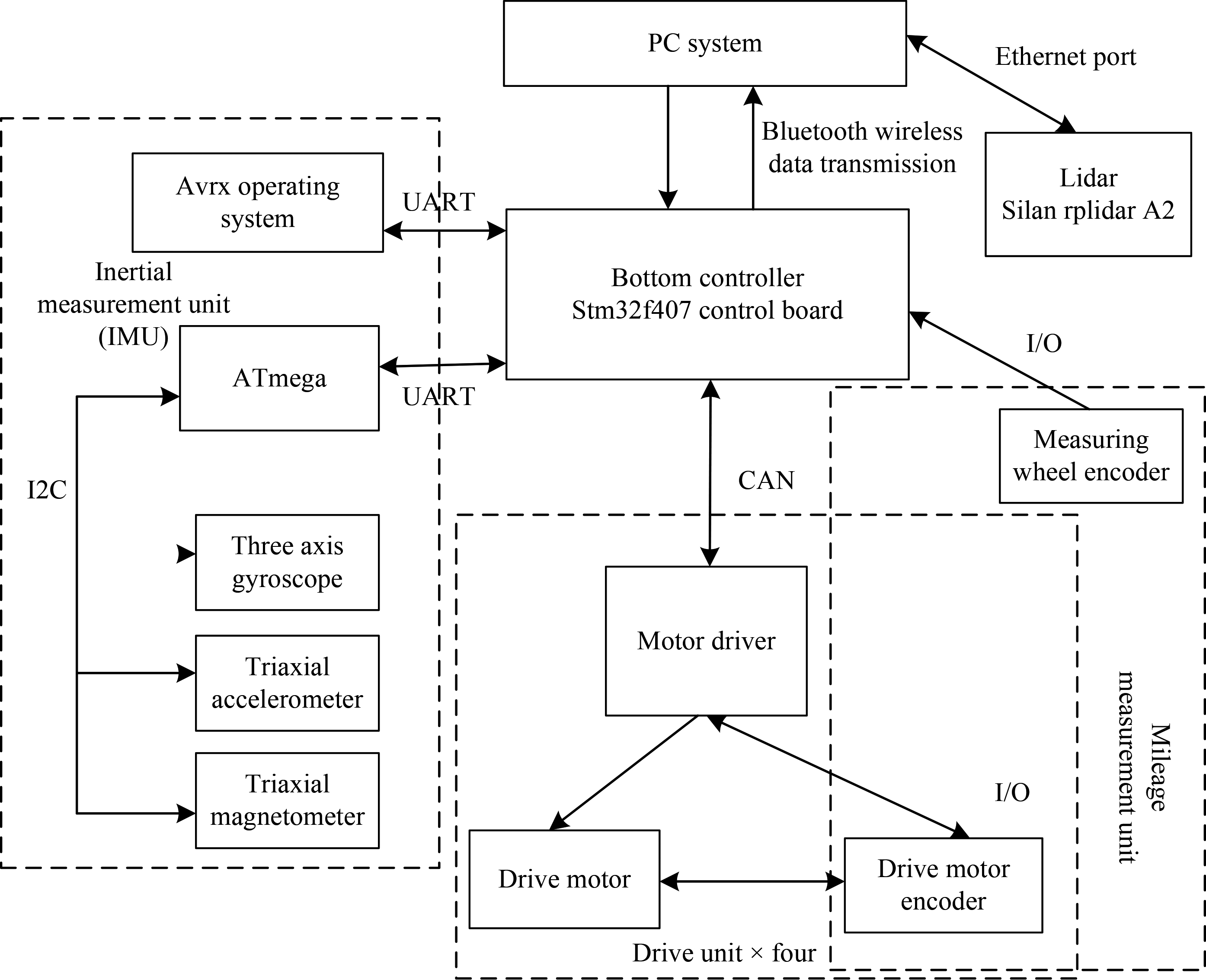
The message communication between the bottom controller of omnidirectional mobile robot system and the upper ROS system is mainly realized through Bluetooth module, which is mainly responsible for transmitting the pose information of mobile robot and the motion control execution instructions of the upper system. The bottom drive controller transmits messages to the four motors through CAN bus, and sets its message transmission rate to 800 kbps [16]. The inertial measurement unit uses UART to realize the communication with the bottom drive control. To enhance the data processing efficiency of the bottom drive controller, the direct access memory mode is adopted, and the lidar is directly connected to the USB serial port to realize the communication with the PC system.
A fuzzy controller is consisted of fuzzy interface, knowledge base, fuzzy reasoning and fuzzy interface. The fuzzification interface is to convert the accurate digital quantity into fuzzy vector and complete the fuzzification of the determined quantity input. The knowledge base consists of rule base and database. Rule inventory contains the rules of fuzzy control, whose function is to provide control rules for inference engine. Rule statement is a language description of our intuitive senses [17]. The database stores the membership vector values of all fuzzy subsets of input variables and all fuzzy subsets of output variables. If the domain is continuous, the database stores the membership function. Its function is to provide data to the inference engine when solving the fuzzy relational equation. Fuzzy reasoning refers to the process of solving the fuzzy relational equation and outputting the fuzzy control quantity based on the fuzzy input quantity provided by the fuzzy interface, the corresponding rules provided by the rule base and the relevant data provided by the database. The function of defuzzification interface is to defuzzify the fuzzy control quantity output by fuzzy reasoning and convert it into a determined control quantity.
Determination of input-output relationship of mobile robot based on multivariable fuzzy controller
When designing fuzzy controller, its biggest advantage is that it does not depend on the controlled object model. At the same time, it also has a huge disadvantage, that is, it is highly dependent on the experience and knowledge of control experts or operators. Without such control experience and knowledge, designers can hardly design a better fuzzy controller. However, the adaptive fuzzy controller can overcome this disadvantage, because it can adjust the relevant parameters of the fuzzy controller online according to the changes of system data, realize the ability of adaptive learning, and make the system have better control effect. In contrast to the traditional adaptive control, the controller can effectively use the linguistic fuzzy information provided by the designer, and has a better control effect on the system affected by highly uncertain factors.
Multivariable fuzzy controller has the characteristics of multivariable structure, so it is very difficult to design it directly. However, the decoupling characteristic of multivariable fuzzy controller can simplify the design of the controller, that is, a multivariable fuzzy controller is decomposed into several single variable fuzzy controllers, and then each single variable fuzzy controller is designed separately. Finally, all single variable controllers are combined to complete the design of multivariable fuzzy controller. The principle flow of fuzzy control is shown in Fig. 3.
The principle flow of fuzzy control.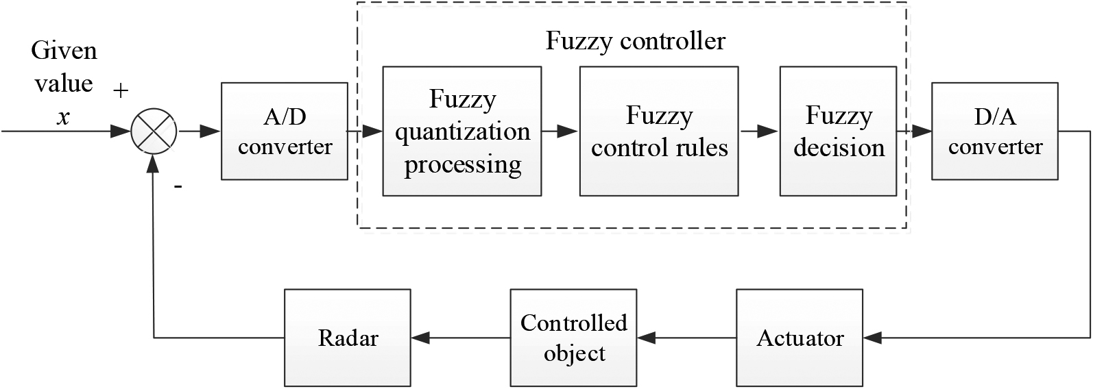
A single variable fuzzy controller is used to approximate a nonlinear function (
Step1: Define
Step2: Complete the rule description of fuzzy system
where,
Step3: Based on product inference engine, single valued fuzzer and central average defuzzifier the fuzzy system
where
Then the fuzzy controller is:
where
All univariate fuzzy controllers are combined to obtain the input-output relationship of multivariable fuzzy controller, which can be expressed as:
where
It can be concluded that the multivariable fuzzy system is essentially a nonlinear mapping from input space
To sum up, the membership degree of the input
After the ground point cloud is removed, for the two-dimensional projection of the remaining point cloud, it is assumed that the two-dimensional grid contains
The data obtained by lidar takes the mobile robot itself as the reference coordinate system, so the grid obtained after projection is composed of two occupation situations, in which black represents the existence of point cloud in the grid and white represents the absence of point cloud in the grid, as shown in Fig. 3.
According to the grid occupation after two-dimensional projection, it can be found that the partially occupied grid will appear isolated or a small amount of accumulation in the overall distribution, which is due to the wrong measurement caused by the uneven ground environment and the existence of dynamic obstacles. When the ground is removed, these point clouds generated by uncertain factors are very easy to accumulate together or exist in isolation in the two-dimensional grid. To enhance the robustness of the algorithm, these wrong measured point clouds need to be eliminated. Therefore, an error measurement method based on grid search in proposed in this study. This method mainly analyzes the current grid occupation and its direct neighborhood grid occupation, and integrates the occupied grids together. The specific process is as follows: first, set the grid index range to
Composition structure of index grid.
Then take the
Neighborhood search area.
In Fig. 5, the black grid represents the grid to be searched, and the grid labeled 1–8 represents the direct neighborhood of the search. Then search 1–8 neighborhood grids successively. If the neighborhood grid is occupied, aggregate the grid and search it repeatedly as a seed until all occupied grids in the neighborhood are searched and aggregated into a set. Then search all grids, set the threshold according to the above aggregation results, and finally filter according to the threshold.
As a typical nonholonomic system, a mobile robot has diverse driving forms. Among them, the following are widely studied: two drive wheeled mobile robot, vehicle type mobile robot and wheeled mobile robot with trailer. For the above robot system, it can be decomposed and modeled from the system hierarchy, which can generally be divided into three categories: kinematics subsystem, dynamics subsystem and motor drive subsystem, as shown in Fig. 6. The kinematic model is the model of mobile robot system, which mainly considers the nonholonomic constraint conditions of pure rolling; the dynamic model is the more essential model of mobile robot, which involves the internal relationship of mass, moment of inertia, external input and binding force, and is usually described by Euler Lagrange equation; and the driving model further considers the relevant characteristics of the robot driving motor, which is closer to the actual control of the mobile robot. Next, the kinematics, dynamics and driving models of the dual rear wheel differential driving wheeled mobile robot are established.
Subsystem diagram of mobile robot.
Nonholonomic mobile robot models can generally be described by generalized mechanical systems:
where
This paper studies a typical double rear wheel differential drive mobile robot. Its driving wheels are driven by two independent DC motors, and an auxiliary front wheel is the support wheel. Let the generalized coordinate of the mobile robot be
Structural diagram of two wheel drive mobile robot.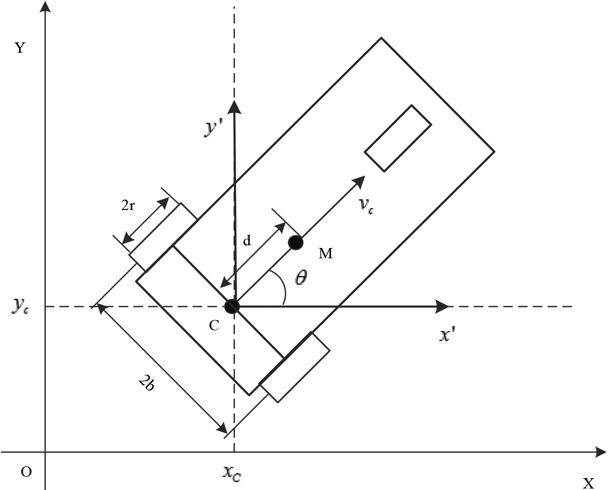
Divide and arrange Eqs (9) and (10) to obtain:
Points
The following velocity relationship can be obtained by deriving Eqs (12) and (13):
The kinematic model of nonholonomic mobile robot with uncertain parameters is:
where
By substituting Eq. (16) into Eq. (17), the general form of kinematic model of mobile robot is obtained.
The centroid
where
The control goal is to find the appropriate angular velocity control inputs
Position and heading tracking error
By differentiating Eq. (21), the error differential equation of the following tracking control system can be obtained:
Through the above transformation, the TRC of the mobile robot can be regarded as a stabilization problem of Eq. (16), that is, the angular velocity control inputs
Schematic diagram of mobile robot trajectory tracking.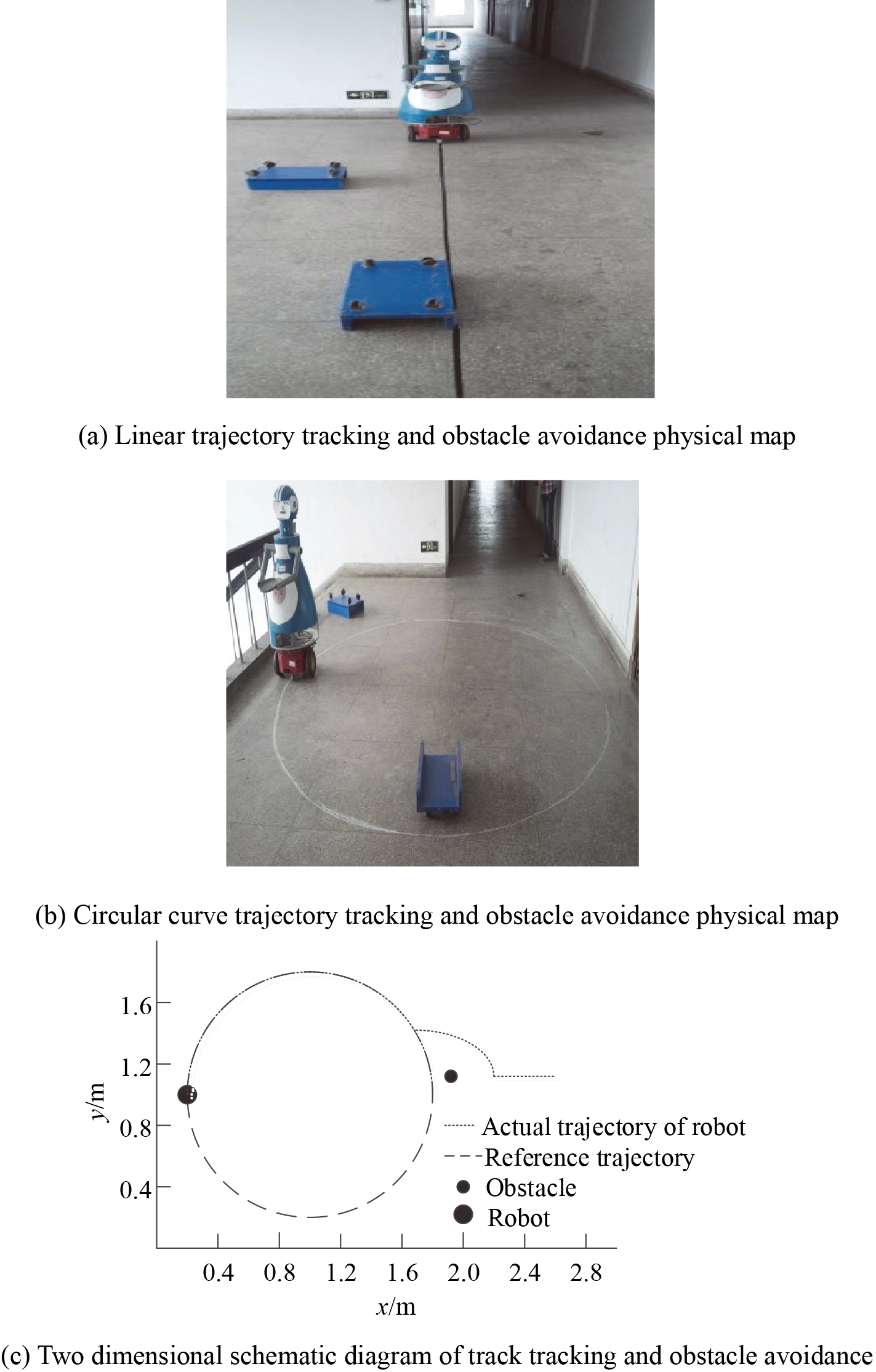
Experimental scheme
To validate the feasibility of the proposed control method, the path tracking simulation is carried out in the environment of MATLAB 2019a. The CPU of PC is Intel Core i8 550U and quad core 1.8 HZ. The circular and linear paths are tracked and simulated. The two paths correspond to the tracking of linear speed and fixed curvature of the path, respectively. The specific tracking site is shown in Fig. 8.
Experimental results
Trajectory tracking accuracy of mobile robot
The trajectory tracking accuracy of the proposed method, the methods in Literature [7], Literature [8], Literature [9] are comparatively analyzed. Trajectory tracking accuracy refers to the fitting degree between the actual motion trajectory of the robot and the referential trajectory.
Trajectory tracking accuracy of mobile robot
Trajectory tracking accuracy of mobile robot
When the number of iterations is 50, the accuracy of mobile robot trajectory tracking of the method in Literature [7], the method in Literature [8], the method in Literature [9] and the proposed method is 82.8%, 83.5%, 82.1%, and 98.6%, respectively; When the number of iterations is 250, the accuracy of mobile robot trajectory tracking of the method in Literature [7], the method in Literature [8], the method in Literature [9] and the proposed method is 79.5%, 69.2%, 72.8%, and 97.9%, respectively. The proposed method has much higher trajectory tracking accuracy than the other methods.
Compare the tracking time of the same mobile robot on the same set of referential trajectory under the trajectory tracking algorithms in different literature. The trajectory tracking time of the proposed method, the methods in Literature [7], Literature [8], Literature [9] are comparatively analyzed.
Track tracking time of mobile robot
Track tracking time of mobile robot
When the number of iterations is 100, the mobile robot trajectory tracking time of the method in Literature [7], the method in Literature [8], the method in Literature [9] and the proposed method is 197 s, 186 s, 178 s, and 6 s, respectively; When the number of iterations is 300, the mobile robot trajectory tracking time of the method in Literature [7], the method in Literature [8], the method in Literature [9] and the proposed method is 321 s, 312 s, 175 s, and 16.2 s, respectively. The proposed method always has high TRC efficiency of mobile robot.
The trajectory tracking error of the proposed method, the methods in Literature [7], Literature [8], Literature [9] are comparatively analyzed. The trajectory tracking error here refers to the mean value of the
Trajectory tracking error curve of mobile robot.
When the number of iterations is 20, the mobile robot trajectory tracking error of the method in Literature [7], the method in Literature [8], the method in Literature [9] and the proposed method is 0.14, 0.20, 0.31, and 0.06, respectively. The overall analysis shows that the minimum trajectory tracking error of the proposed method is only 0.05, indicating the trajectory tracking error of the proposed method is smaller than other methods.
In this study, a TRC method of mobile robot based on AVRX operating system is proposed. Firstly, the principle of AVRX operating system is analyzed and the hardware structure of mobile robot is designed. The input-output relationship of mobile robot trajectory is determined according to multivariable fuzzy controller. Eliminating the wrong data of mobile robot trajectory tracking information through point cloud measurement. The TRC model of mobile robot is designed by Euler Lagrange equation to realize the TRC of mobile robot. The main conclusions can be drawn:
When the number of iterations is 250, the trajectory tracking accuracy of the proposed method is 97.9%, which is the highest of all comparison methods. When the number of iterations is 300, the trajectory tracking time of the proposed method is 16.2 s. The results show that the proposed method can improve the trajectory tracking efficiency of mobile robot. The minimum trajectory tracking error of the proposed method is only 0.04, which shows that this method can improve the TRC effect of mobile robot.
The designed method improves the trajectory tracking accuracy of the mobile robot, reduces the trajectory tracking error, shortens the trajectory tracking time, and therefore improves the trajectory tracking control effect of the mobile robot. The trajectory tracking control effect of the proposed method for robots in complex environment will be verified through testing to improve the universality of this method in the next research.