
Abstract
It is a fuzzy internal mode PID temperature control system designed for solid electric storage heating systems with high inertia, hysteresis, and nonlinearity. Experimental results demonstrate that the control strategy has a high level of model adaptability and anti-interference capability for the changing operating conditions of solid-storage boilers, that the system overshoot is steadily controlled within 5% and that hysteresis cannot adversely affect the stability of the control system, that the control accuracy of water supply temperature can reach
Quotes
The rapid development of China’s power industry has brought solid-storage electric boilers to the fore as one of the clean energy boilers. However, compared to gas boilers, electrode boilers, etc. it was developed later and has many problems in the control scheme and strategy, while the object that needs to be controlled and the temperature exhibits nonlinearity, a large inertia, and a large hysteresis. When using the furnace, the temperature of the solid storage boiler will continue to drop, and the system operating conditions will constantly change. Because of this, it is difficult to satisfy the control requirements of the solid-state electric storage control system using conventional control techniques. For a time-lag system, the internal mode control has a good control effect; however, in practice, there is often a large discrepancy between the actual model of the system and the internal mode control; when this discrepancy is large, the control effect is greatly diminished. Based on the most influential system parameters, the transfer function under various conditions can be determined through the use of fuzzy control theory [1, 2, 3]. In operation, the system is controlled using internal mode PID, and the output of the fuzzy controller is used to adjust the parameters online in order to achieve fuzzy internal mode PIcontrol. This is designed to control the water supply temperature of the solid electric storage boiler.
Fuzzy internal mode PID
Traditional PID control algorithm
PID control principle.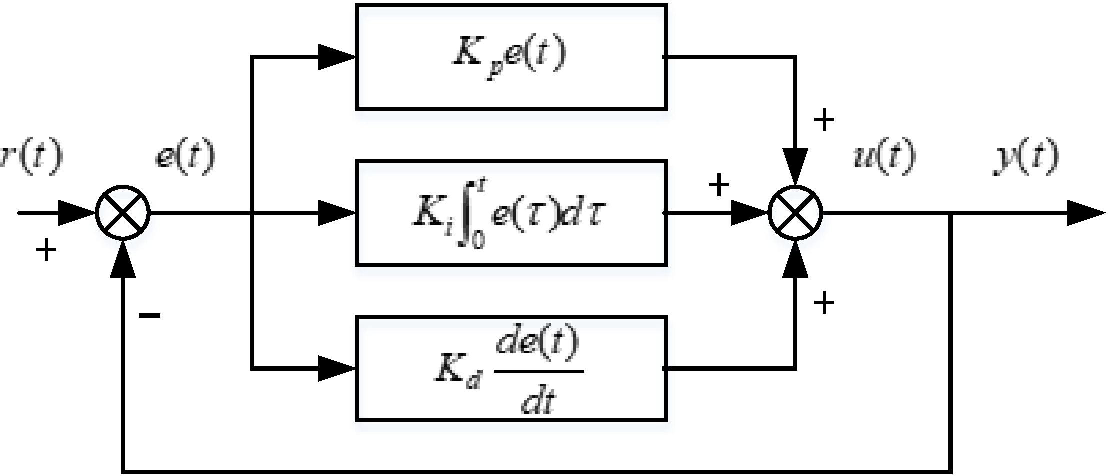
Figure 1 illustrates that traditional PID control is a linear controller composed of a linear superposition of proportional, integral, and differential coefficients. The proportional, integral, and differential coefficients can be adjusted to meet the fundamental requirements of industrial control.
According to Fig. 1, traditional PID control is a linear controller composed of the linear superposition of proportional, integral, and differential coefficients. Its greatest advantage lies in its simple structure, its high stability, its reliable operation, and its ease of adjustment, allowing it to meet the basic requirements of industrial control by adjusting proportional, integral, and differential coefficients.
The law of the PID control method is
By applying the Laplace transformation to Eq. (1), we can obtain
where:
As shown in Fig. 1 and Eq. (1), the greatest advantage of the traditional PID control algorithm is an independent control mechanism independent of the mathematical model of the controlled object’s control strategy. This eliminates the error between the controlled object and its target. However, with the advancement of science and technology, as well as the improvement of control quality requirements, the shortcomings and flaws of the traditional PID control algorithm have been brought to light. Signal processing is simple, and when there is a slow control system and inertia links, the controller fails to receive timely and accurate error feedback, affecting the output of the controller and, in severe cases, causing the output to oscillate.
Figure 2 illustrates the structural block diagram of the internal mold control system.
Structural block diagram of the internal mold control system.
The output
where
It can be deduced from Eq. (3) under the assumption that the model is error-free, i.e., the estimated model of the controlled process
If
Assuming the estimated model is “invertible”, i.e.,
As can be seen, when the estimation model is error-free and “invertible”, this internal mode controller can completely resolve the impact of disturbances on the entire control system, regardless of the variations of disturbances
Similarly
Equation (7) shows that the ideal internal mode controller ensures that the system output
The internal-mode controller shown in
Therefore, it is typically necessary to add the corresponding filtering link to form the actual internal mode control in the situation described above.
When designing the internal mode controller, the specific step is to decompose the internal model into the product of two factors, i.e.
where:
The internal mode controller is defined as
where
where:
Substitute Eqs (9) and (10) into Eq. (4), and when
According to Eq. (11), the filter
Internal mode PID controller design
Equivalent variation structure of the internal mode control system.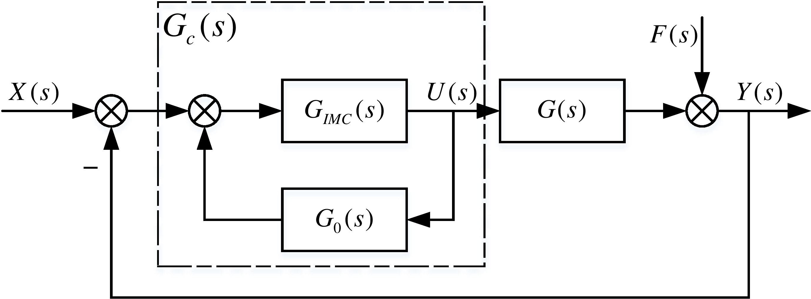
The equivalent transformation is performed on the internal mode control system, and Fig. 3 illustrates the equivalent change structure of the internal mode control system.
In Fig. 3,
According to Fig. 3, we can obtain
For the solid state electric heat storage system, a typical first order inertia coupled with lag link is used as a mathematical model of its controlled object, which is
For the lag
i.e.
Therefore
Substituting Eqs (9), (10), (15) and (16) into Eq. (12) gives
Equation (2) describes the transfer function of a conventional PID controller. We design an internal-mode PID controller by rewriting the controller
Thus Eq. (17) after mathematical transformation gives
In Eq. (18), it can be seen that
It can be seen from Eq. (18) that the controller
The filter parameters
Fuzzy logic control, also known as fuzzy control, is a nonlinear control. Fuzzy control differs from conventional PID control in that it utilizes linguistic variables rather than numeric values to describe the system. Therefore, fuzzy control can greatly simplify the design of a control system without requiring a very detailed mathematical model of the controlled object and can have an excellent control effect on complex nonlinear processes, particularly for nonlinear, incomplete model systems.
However, simple fuzzy controllers lack an integration link, and they can provide good control for nonlinear, incomplete model systems, though it is difficult to eliminate the steady-state error of the control system.
As a consequence, by adding a fuzzy controller to the internal mode PID controller, the output of the fuzzy controller is controlled in accordance with the size of the system’s deviation and the rate of change of the system’s deviation when the input and output of the system are consistent, under the influence of fuzzy rules, to achieve the online adjustment of the filter parameters
Figure 4 depicts the structural block diagram of the fuzzy internal mode PID.
Block diagram of the structure of fuzzy internal mode PID.
(1) Determination of language variables
The magnitude of the system deviation
(2) Define the input and output fuzzy sets
The rules for defining the fuzzy sets of the magnitude of the deviation
The magnitude of the deviation
(3) Select the input and output affiliation function
Figure 5 depicts Gaussian affiliation functions for taking the magnitude of the deviation
(4)
The control rule table can be derived by summarizing the control experience of the solid electric storage heating temperature control system. When the error is small, the primary objective should be to prevent overshoot in order to select the corresponding control amount; when the error is large, the primary objective should be to quickly eliminate the error in order to select the corresponding control amount.
Table 1 illustrates the
Affiliation function for deviation change ec.
Affiliation function of the filter parameter increments 
Solid electric heat storage heating control process
The test site is a university demonstration project for solid-storage heating. The solid electric storage heating system uses nighttime low valley electricity to store heat in the heat storage bricks and a fan to heat the heat within the heat storage body through a heat exchanger for air and water exchange to heat some university buildings, integrating heat source and heat exchange station. The demonstration project not only serves as an internal heat source for the university, but it is also equipped with a good monitoring interface and a large number of measurement points that can be used as a platform for teaching experiments and can offer students a broader range of experimental conditions.
Heating process of the solid state electric storage heating system.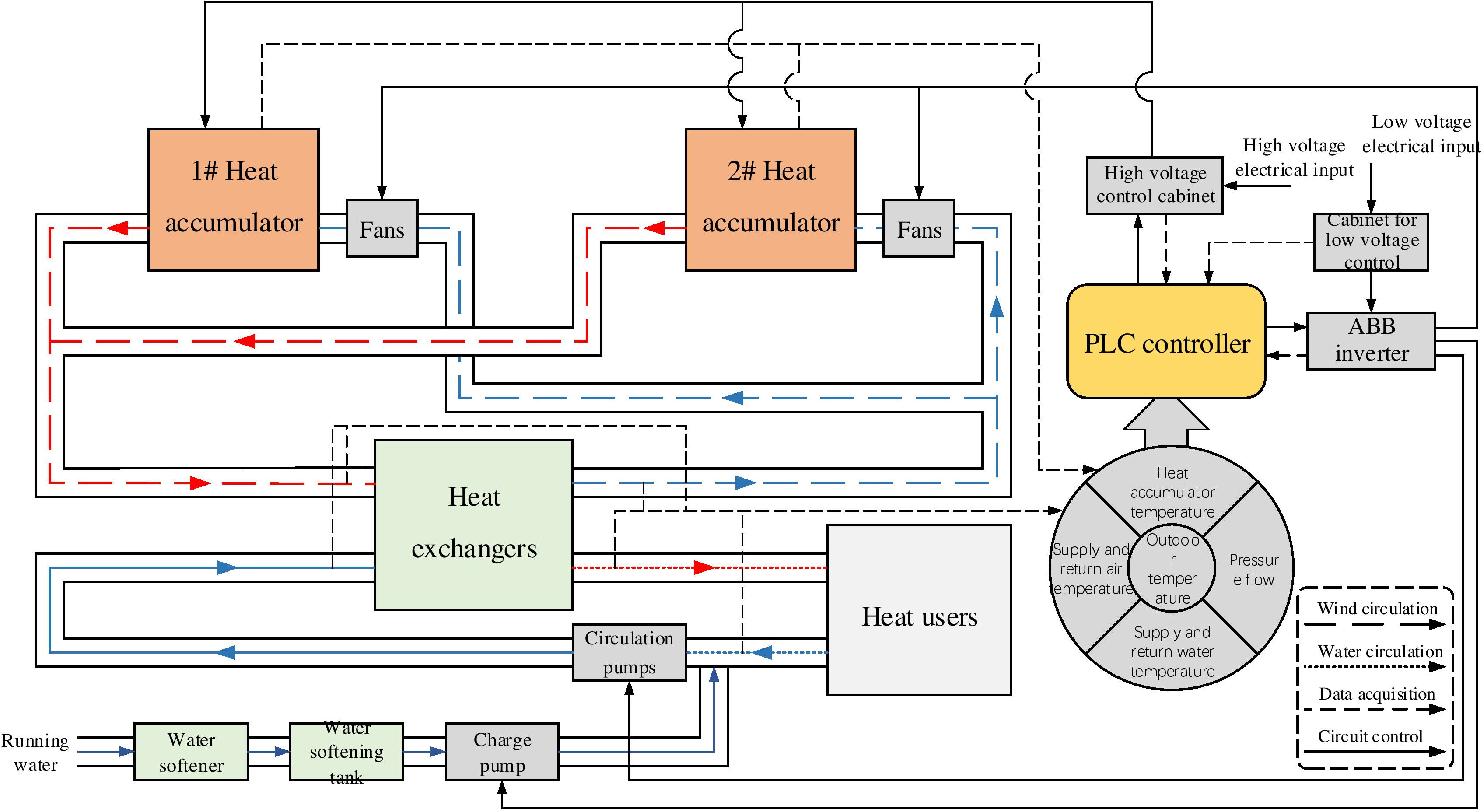
Figure 7 depicts the heating process of this solid electric storage heating system. This demonstration project’s heat source is two 1.5 MW heat storage units; the control equipment consists of variable frequency fans, variable frequency circulation pumps, variable frequency charge pumps, and a number of dampers; and the measurement points include temperature, pressure, flow rate, etc.
Wind-water heat exchange is carried out in the heat exchanger via wind medium and water medium, and the heat transfer process is characterized by high inertia and high hysteresis. For such control systems with large hysteresis and large inertia, it is difficult for the traditional PID control to meet its control requirements; therefore, the IMC-PID controller is used in place of the traditional PID controller, and the fuzzy controller is added to realize online control. The fuzzy internal mode PID controller is designed to optimize the control of the entire solid state electric storage temperature control system by adjusting the filter parameters
This entire system utilizes the concept of “heat storage at night and heat supply during the day”. The heat accumulator is heated at night using low valley electricity, and during the day, all equipment is monitored and data is collected by a PLC as per the set program, and operating equipment is controlled based on the collected data to ensure stable heat supply.
The control structure diagram of this control system is shown in Fig. 8. In Fig. 8, the fan is depicted as an actuator, while the heat exchanger is a controlled object.
Block diagram of solid state electric storage heating temperature control system.
The block diagram of the transfer function of c 10 is shown in Fig. 9.
Block diagram of the transfer function of the solid-state electric storage heating temperature control system.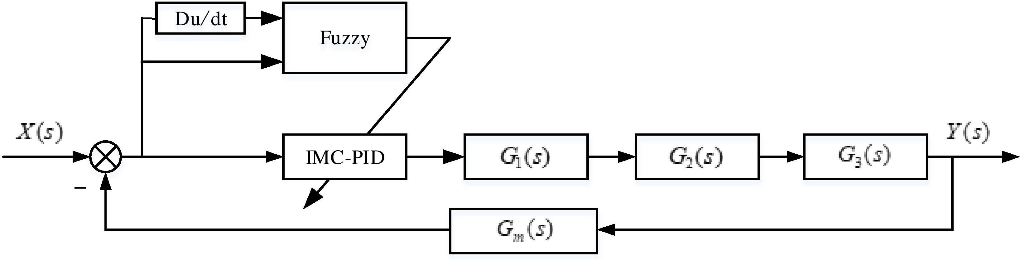
According to the IMC-PID control theory approach, it is necessary to first establish a mathematical model of the controlled object. As shown in Fig. 9, i.e., the expression of the function of
Under the condition of employing a conventional PID controller, the step response of the entire control system is experimented, the response curve of the water supply temperature output quantity is determined based on the data obtained from the experiment, and the parameters
For the step response experiments, the following experimental equipment was chosen: one heat accumulator (power 1.5 MW), three wind turbines (each power 5.5 KW), and two heat heat exchangers (vacuum phase change heat exchangers with respective power of 330 KW and 400 KW).
Under the working condition that the heat accumulator furnace temperature is 350
Figure 10 depicts the corresponding response curve.
Equivalent corresponding curve.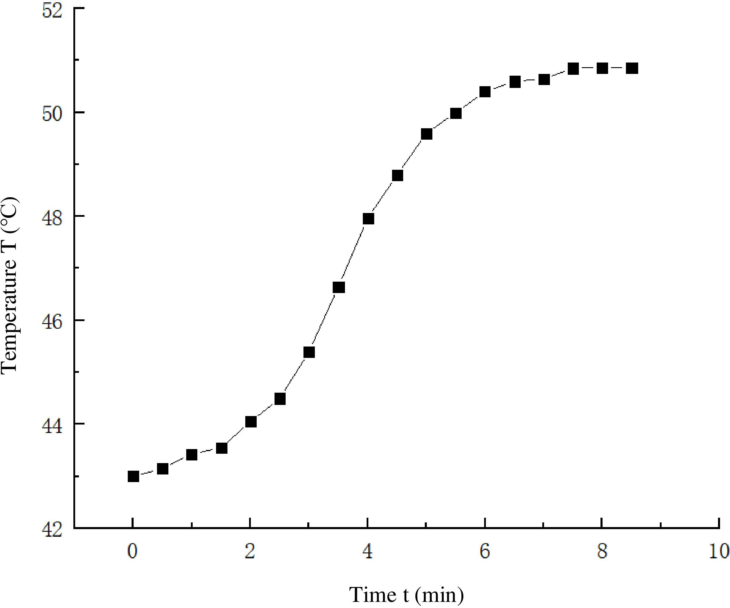
[baseline=(char.base)] [shape=circle,draw,inner sep=0.2pt] (char) 1; According to the graph, we can calculate
[baseline=(char.base)] [shape=circle,draw,inner sep=0.2pt] (char) 2; Calculate
Select the points
Similarly, take
Take the average of the above three sets of data to obtain
[baseline=(char.base)] [shape=circle,draw,inner sep=0.2pt] (char) 3; Model determination
By substituting the results of [baseline=(char.base)] [shape=circle,draw,inner sep=0.2pt] (char) 1; and [baseline=(char.base)] [shape=circle,draw,inner sep=0.2pt] (char) 2; from
If the controlled system’s dynamic characteristics include
The touchscreen-based integrated management interface.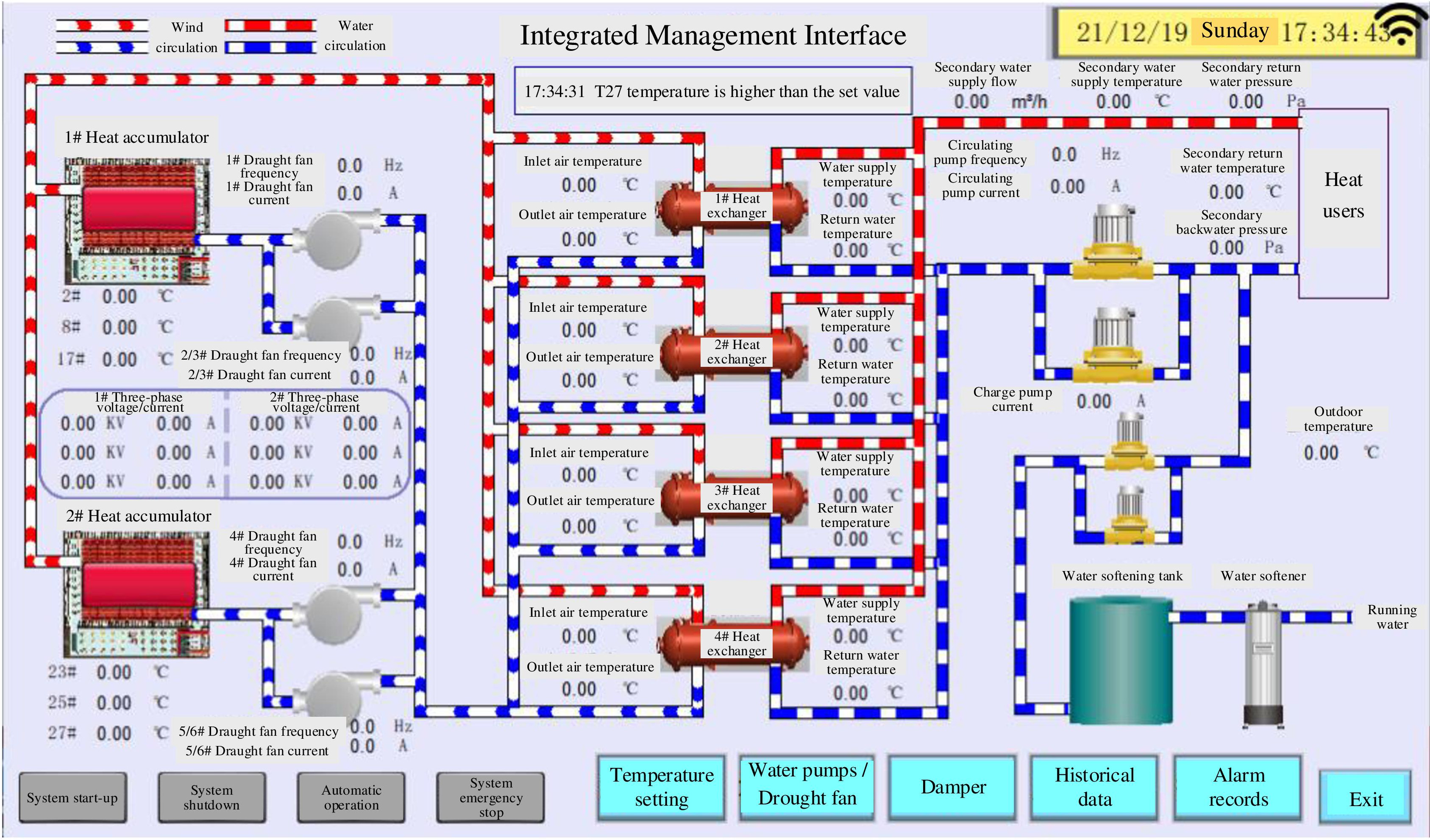
Compared to the actual project, the demonstration project needs not only be used as a reliable heat source for schedule heating of some school buildings, but it should also include a large number of analog and digital input and output points as well as a good monitoring screen to facilitate daily experimental teaching for students.
The controller of the control system is chosen to use three PLCs (Siemens S7-200SMART), and the monitoring system is equiped with a touch screen, paperless recorder, and SCADA monitoring system for remote control. The three PLCs are divided into one master station and two slave stations, with the master station primarily acting as the control operation and issuing control commands, and the slave stations being responsible for data acquisition and control of the dampers respectively, data communication through Ethernet, and coordination control of the entire control system; the paperless recorder primarily collects other data not involved in the control, stores them on a time-based axis, and displays them in various forms of screens (digital, bar graph, curve, etc.). SCADA as remote monitoring will record all real-time data and operation records of the entire control system and display them on the screen for real-time monitoring and storage.
Figure 11 depicts the integrated management interface of the touch screen.
Partial control program.
Because the S7-200SMART PLC is essentially a microcomputer, the internal model control algorithm is discretized. The mathematical operation instructions of the ladder language are used in STEP 7-Micro/Win software to perform a series of four operations on the data. This is what is implemented in the PLC [5]. Using the indirect addressing method, complete the control scale query, de-fuzzify the query results
The partial control program is shown in Figure 12.
Experimental validation
Three different working conditions will be designed for the step response experiment to account for the uncertainty of external disturbances and the chance of the experimental process. For comparative and analytical purposes, the temperature profiles of the output quantities of the conventional PID controller and the fuzzy internal mode PID controller under different working conditions will be collected.
The parameters
Data acquisition
250
C furnace temperature

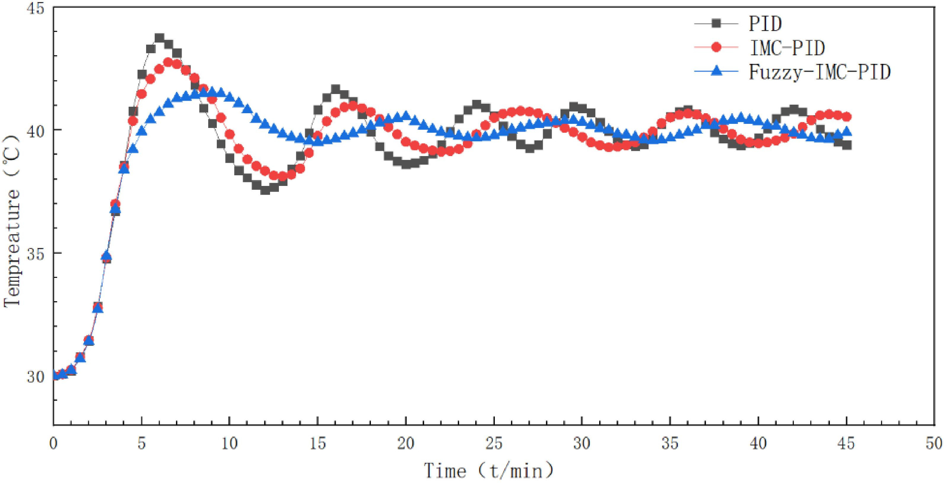
Under the working conditions that the accumulator furnace is heated to 250
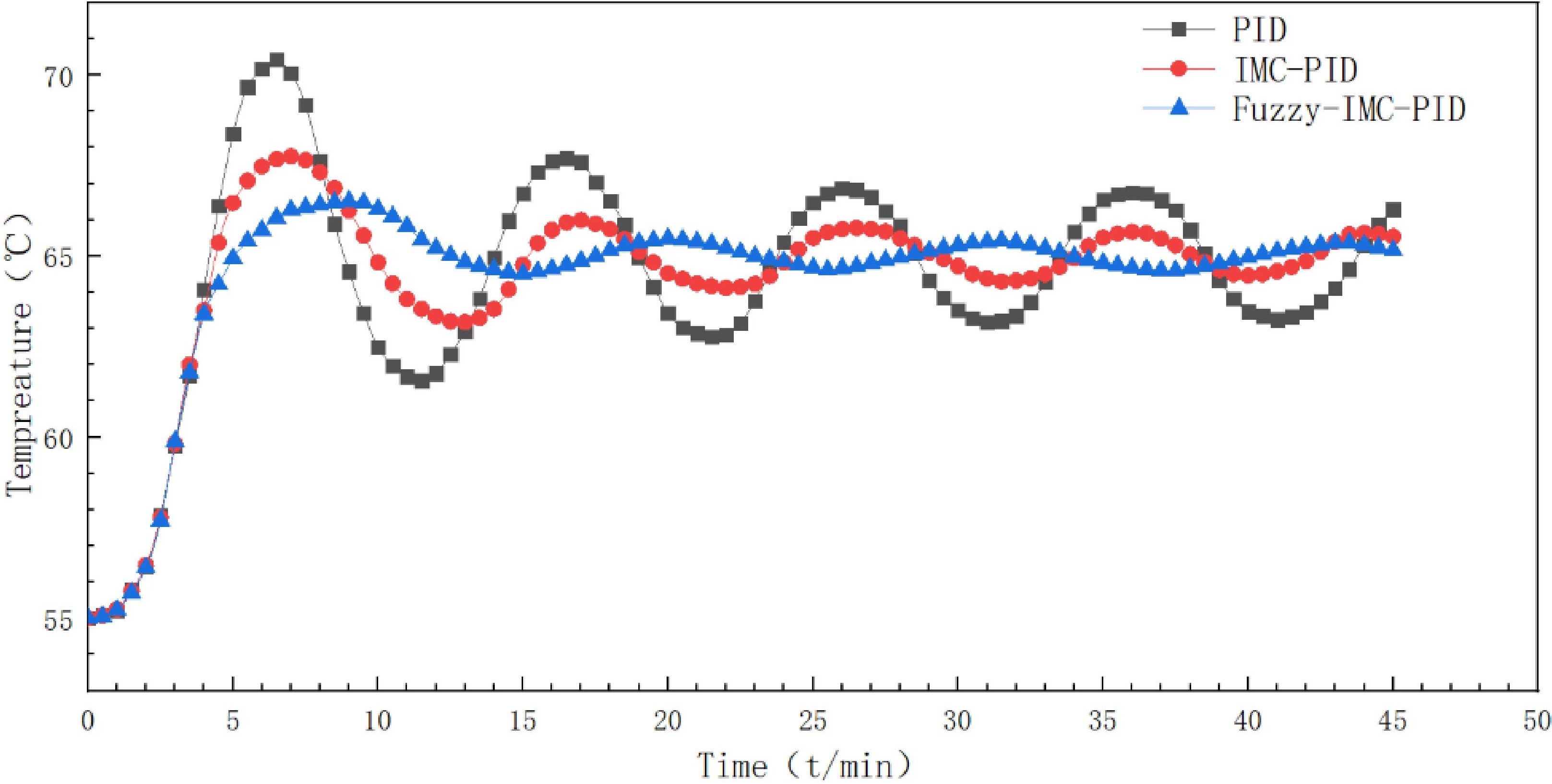
Under the conditions that the accumulator furnace is heated to 350
450
C furnace body temperature
Under the working condition that the accumulator furnace is heated to 450
Data analysis
The IMC-PID controller compensates for the hysteresis of the control system in comparison to the traditional PID controller, as shown in comparative analysis of Figs 13, 14 and 15. However, in the experimental process, the temperature of the solid storage boiler decreases slowly, accompanied by an uneven distribution of temperature within the furnace, and the operating conditions of the whole system change continuously.
When fuzzy control is used to form a fuzzy internal mode controller, the system can follow the change in the working conditions to adjust the controller parameters online, which greatly improves the amplitude of the oscillation of the control system, controlling the overshoot within 5% and the control accuracy within
Conclusion
The solid electric storage heating temperature control system has large inertia and hysteresis links, and the fuzzy internal mode PID controller is superior to the traditional PID control and IMC-PID controller. IMC-PID control facilitates the simplification of controller parameters in the control system, whereas fuzzy control facilitates the online adjustment of controller parameters in the control system in response to varying operating conditions. Through experimental analysis, the fuzzy internal mode PID control provides the control system with improved anti-interference capability, robustness, and control accuracy, as well as a higher performance index than the conventional control algorithm, thereby enhancing its application value.
Footnotes
Acknowledgments
This work is supported by the Hebei Province Innovation Capability Enhancement Project (19244503D), Postgraduate Innovation Fund Project of Hebei Province Colleges and Universities (CXZZSS2022060) and Hebei Key Project of Research and Development Plan (20374504D).