
Abstract
Thermoelectricity technology, as a kind of cost-effective and pollution-free power generation solution, is often used for waste heat recovery and utilization. In this paper, the temperature distribution of a Two-stage Thermoelectric Generator (TTEG) under constant temperature conditions has been studied using a one-dimensional heat conduction model. Moreover, by combining the obtained temperature distribution with the three-dimensional size of TTEG, a calculation formula of resistance and voltage was developed based on the calculus method. When the sum of cross-sectional areas of all the PN-type thermoelectric arms respectively in high- and low-temperature layers is constant, the optimal ratio between cross-sectional areas of a single PN-thermoelectric arm respectively in high- and low-temperature layers can be calculated using the proposed formula in this study to achieve the maximum output power. Results also showed the relationship between the heights of PN-type thermoelectric arms and the temperature distributions in high- and low-temperature layers. Using PbTe as the medium temperature thermoelectric material and Bi
Nomenclature
Greek symbols
Abbreviations
Subscripts
Introduction
Thermoelectric power generation technology is a kind of power generation technology based on Seebeck effect, which has the advantages of simple structure, long life and no pollution. At present, the technology is commonly used in the utilization of solar energy, waste heat of internal combustion engines and waste heat in other places. In the research of thermoelectric technology, the research of TTEG is less. The reason is that the TTEG may effectively increase the voltage value of the Thermoelectric Generator (TEG), but the resistance value increases due to the increase of the contact point between the thermoelectric material and the copper plate, which leads to the decrease of output power. The STEG can effectively avoid these, so the research of TTEG is relatively small. Compared with the traditional single-stage TEG, the TTEG can place different thermoelectric materials in a more appropriate temperature range, so it has higher performance. The manufacturing method of the TTEG is similar to that of the traditional TEG, and the production cost of the TTEG is lower than that of the STEG.
The researchers improved the performance by optimizing the mechanism of the TEG. Liu et al. [1] improved the output power and conversion efficiency of TEG by combining the optimization method with computer-aided analysis by means of multi-objective optimization. Liu et al. [2] applied the profile-based genetic algorithm to the optimal fin parameters, which can increase the average temperature and decrease the pressure drop by approximately 20%. Min et al. [3] studied the figure of merit of the TEG with a large temperature differential, and concluded that the Thomson effect has a greater impact on a STEG than on the cascaded TEG when the figure of merit is measured.
Manikandan et al. [4] studied the thermodynamic model of TTEG considering Thomson effect, Joule heat and Fourier heat conduction. The number of thermocouples is optimized according to the maximum output power and energy/exergy efficiency conditions. Sun et al. [5] studied the performance optimization of TTEG structure by using multi-objective genetic algorithm, which considered the influence of different thermal effects and analyzed the energy destruction ratio. Based on a thermodynamic model of a TTEG, Zhang et al. [6] Studied the performance of TTEG by using Latin hypercube sampling method to simulate the change of TEG parameters. It is found that the large temperature difference between the cold and hot ends of TTEG will not only improve the output power of the structure, but also reduce its stability. Liu et al. [7] proposed a novel model for TTEG from vehicle exhaust and set up an experiment to test. The experimental results show that the maximum output power is about 250 W and the system thermal efficiency can reach 5.35%. Arora et al. [8] simultaneously optimized the maximum output power, minimizing entropy generation and thermal efficiency of the proposed TTEG system based on the second version of non-dominated sorting genetic algorithm with working current, temperatures and number of thermoelectric arms in the two stages of the TTEG as design variables, which shows that the optimization result of three objectives is better than that of two objectives. By comparing the performance of two- and three-stage cascaded TEGs, Kanimba et al. [9] found that the output power of three-stage cascaded TEG is 21% higher than that of TTEG when the maximum hot side temperature and the fixed cold side temperature are 973 K and 473 K, respectively. Sun et al. [10] established a model of TTEG and parallel TEG, and concluded that under the conditions defined by the authors, the performance of a single-stage TEG is superior to that of a TTEG when the hot side temperature is below 600 K. Liang et al. [11] studied the application of TTEG in the waste heat of internal combustion engine, and optimized the structure of TTEG, and obtained the optimal ratio range of the numbers of thermocouples in high-temperature layer and low-temperature layer. Atouei et al. [12] proposed a TTEG with Phase Change Material (PCM) applied between two thermoelectric generators to improve the performance of the thermoelectric generator by using the characteristic that the PCM can absorb heat energy as latent heat. The results show that the electrical potential generated by the TTEG with PCM was 27% higher than that of the single-stage TEG. Maduabuchi et al. [13] proposed and studied a two-stage solar TEG with P-type and N-type thermoelectric arms as X-type. This new structure raised the load requirements than a traditional design.
In addition to the above structural optimization methods, researchers also combine TEG with other energy systems to form hybrid systems in order to achieve better performance. Lin et al. [14] established a new hybrid system model consisting of an Alkali Metal Thermalelectric Converter (AMTEC) and a TTEG, and derived the mathematical expressions of out power and efficiency of AMTEC, TTEG and the hybrid system. Guo et al. [15] put forward a new hybrid system composed of a High-temperature Proton Exchange Membrane Fuel Cell (HT-PMEFC), a regenerator and a TTEG, and The results show that the maximum power density and the corresponding electric efficiency of the hybrid system are 11.8% and 17.5% higher than those of the sole HT-PEMFC system, respectively. Liu et al. [16] proposed a new hybrid system model that integrates a Direct Carbon Fuel Cell (DCFC), a TTEG and a regenerator, and found that the maximum attainable power density of the new hybrid system allows about 50% larger than that of the stand-alone DCFC. Guo et al. [17] proposed a hybrid system consisting of a Molten Carbonate Fuel Cell (MCFC) and a TTEG, and concluded that the hybrid system is not only superior to the single MCFC, but also superior to the hybrid system consisting of a MCFC and a single-stage TEG. The above studies on TEG were all based on using the average values of
In addition to the above studies, many researchers established one-dimensional physical models to study the performance of TEG. Barry et al. [18] optimized the structural parameters of thermoelectric arms by using the one-dimensional thermal resistance network model, and the maximum output power and conversion efficiency of the TEG were increased by 10.4% and 3.2%, respectively. Zabrocki et al. [19] extended the linear thermodynamics of irreversible processes by assuming the material parameters of
Due to the low efficiency of the TEG, the internal temperature distribution is mainly determined by the temperatures of the hot and cold ends. Therefore, in the simplified theoretical model developed in this paper, only the influence of the hot and cold end temperatures on the TEG thermoelectric arm is considered. Based on a one-dimensional heat conduction model, the heat distribution of PN-type thermoelectric arms in TTEG was analyzed. The relationship between the maximum output power, the height and the cross-sectional area of PN-type thermoelectric arms in high- and low-temperature layers has been derived. For TTEG, when the temperatures of the hot end and the cold end and the average temperature of the middle ceramic are known, the optimal ratio between the heights of the upper and lower PN type thermoelectric arms and the ratio between the cross-sectional areas of a single PN type thermoelectric arm respectively in upper and lower layers can be calculated using a mathematical expression. The mathematical expression provides a new idea for the structure optimization of TTEG. By optimizing the structure of TTEG, in addition to the advantages of lower production cost, the power generation can also be significantly improved to exceed that of STEG.
Principle of calculation
Heat conduction is caused by the temperature gradient inside the object, and solid temperature conduction is caused by the collision of molecules and the migration of free electrons. In the process of analysis, if the scattering of temperature in the air is not considered, it can be simplified as a one-dimensional heat conduction process. The mathematical expression for the quantity of heat transferred
Equation (1) can be rewritten as follows
One-dimensional steady heat conduction: (a) a homogeneous plate; (b) two-layer homogeneous plate; (c) n-Layer homogeneous plate.
As shown in Fig. 1a, when the thermal conductivity is constant and the temperatures of both surfaces are uniform and constant, Eq. (3) can be obtained.
Where
Equation (3) can be extended to the case of a two-layer composite plate as shown in Fig. 1b. Under steady-state conditions, the rate of incoming heat flow from the left surface is equal to the rate of outgoing heat flow from the right surface [26].
By extending Eq. (4) to n-layer composite plates, the following equation is obtained
For thermoelectric materials in TEG, the thermal conductivity varies with temperature. Taking
Equation (6) can be simplified to obtain Eq. (8).
When the total height of the material is
One-dimensional steady-state heat conduction diagram of TTEG.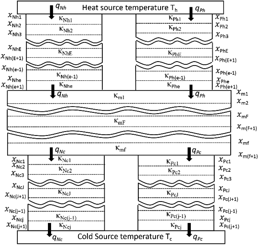
For the TTEG, the thermal conductivity of the copper plate and the middle ceramic is obviously higher than that of the thermoelectric material. Therefore, in the high-temperature layer, the cold end temperature difference between N-type and P-type thermoelectric arms is not large. Therefore, in the analysis process, the hot end temperature of the middle ceramic can be assumed to be a constant value
Where
Because the thermal conductivity of the thermoelectric material is obviously less than that of the ceramic and the copper sheet, it can be assumed that the surface temperature of the middle ceramic is the same. Therefore, it can be assumed that the hot end temperature of the middle ceramic is
The P-type and N-type thermoelectric arms of the thermoelectric generator are cuboids. When the conductivity of the material is determined, the expression of its resistance can be derived as shown in Eq. (11).
For a TTEG, the heights of the P-type and N-type thermoelectric arms in the same layer should be equal. Therefore, we can calculate the resistance values of the P-type and N-type thermoelectric arms in the high-temperature layer and low-temperature layer of the TTEG by combining Eqs (9) and (11). The expressions are as shown in Eq. (12).
The resistance and cross-sectional area of the PN-type thermoelectric arms are shown in Eq. (13).
Equation (12) can also be simplified into Eq. (14) by calculus.
The constants of
Through calculation, it is known that when the values of
By substituting Eq. (13) into Eq. (16), it can be calculated that the expressions of
It can be seen from Eq. (16) that the ratio of the cross-sectional areas of the PN-type thermoelectric arms in a single layer is not related to the height of the thermoelectric arms, but is only related to the selected temperature. Therefore, when the temperature is determined, the ratio of the cross-sectional areas of the P-type and N-type thermoelectric arms can be calculated by using Eq. (16).
Equation (18) can be derived by Eq. (6).
Equation (10) is combined with the TTEG to derive Eq. (19).
Equation (18) can be used to further simplify Eq. (19) to obtain Eq. (20).
By simplifying Eq. (20), the relationship between the temperature and the height of the thermoelectric arm respectively in the high-temperature layer and the low-temperature layer can be derived as shown in Eq. (21).
Seebeck effect is the main principle of thermoelectric power generation. When the cold end temperature and hot end temperature of a thermoelectric material are determined, the voltage value is shown in Eq. (22).
Where
When it is assumed that there are
The total resistance of the TTEG is shown in Eq. (25).
The minimum resistance and voltage of the TTEG can be calculated by Eqs (17) and (23). When the voltage and resistance are determined, the maximum power can be calculated by Eq. (26).
The P-type and N-type thermoelectric arms in the TTEG are connected by a copper sheet, and the electrical conductivity of the copper is far greater than that of the P-type and the N-type thermoelectrical material. Therefore, in the calculation process, the resistance of the connecting pieces is not considered, and the resistance caused by the welding of the current guide plate and the thermoelectric material is also not considered. That is, only the resistance of the P-type and N-type thermoelectric arms is calculated in the calculation process.
When the external resistor forms a closed circuit, the temperature of the cold end and the hot end is still the main factor affecting the temperature distribution in the PN-type thermoelectric arms due to the low efficiency of the TTEG, so the resistance of the TTEG itself can be assumed to be unchanged after the external resistor is connected.
Equations (23) and (25) are substituted into Eq. (26), and the out power of TTEG in the unit area can be calculated by considering that the total cross-sectional area of the TTEG piece is
Substituting Eq. (24) into Eq. (27) yields Eq. (28).
Assuming
At the beginning of the design, in order to ensure a large out power of the TTEG, the ratio of the total cross-section area of the PN-type thermoelectric arms to the area of TTEG should be as large as possible. However, if the distance between the two thermoelectric arms is too small, thermal interference will occur, thus affecting its out power. Therefore, it can be assumed that the ratio of the total cross-sectional area of the PN-type thermoelectric arms to the area of the TEG should have a maximum value. During the design process, if
According to Eq. (29), the out power of the TTEG in unit area is related to three values of
Substituting Eq. (30) into Eq. (29) gives the maximum value of
In the selection of thermoelectric materials, the dimensionless figure of merit ZT is often used to express the performance of thermoelectric materials, and its expression is as shown in Eq. (32).
Bi
As shown in Fig. 3d, the temperature of the ZT value crossing point of the P-type thermoelectric material is at a position of about 474 K, and the temperature of the ZT value crossing point of the N-type thermoelectric material is at a position of about 539 K.
The material properties of different thermoelectric materials: (a) thermal conductivity; (b) Seebeck coefficient; (c) resistivity; (d) the value of ZT.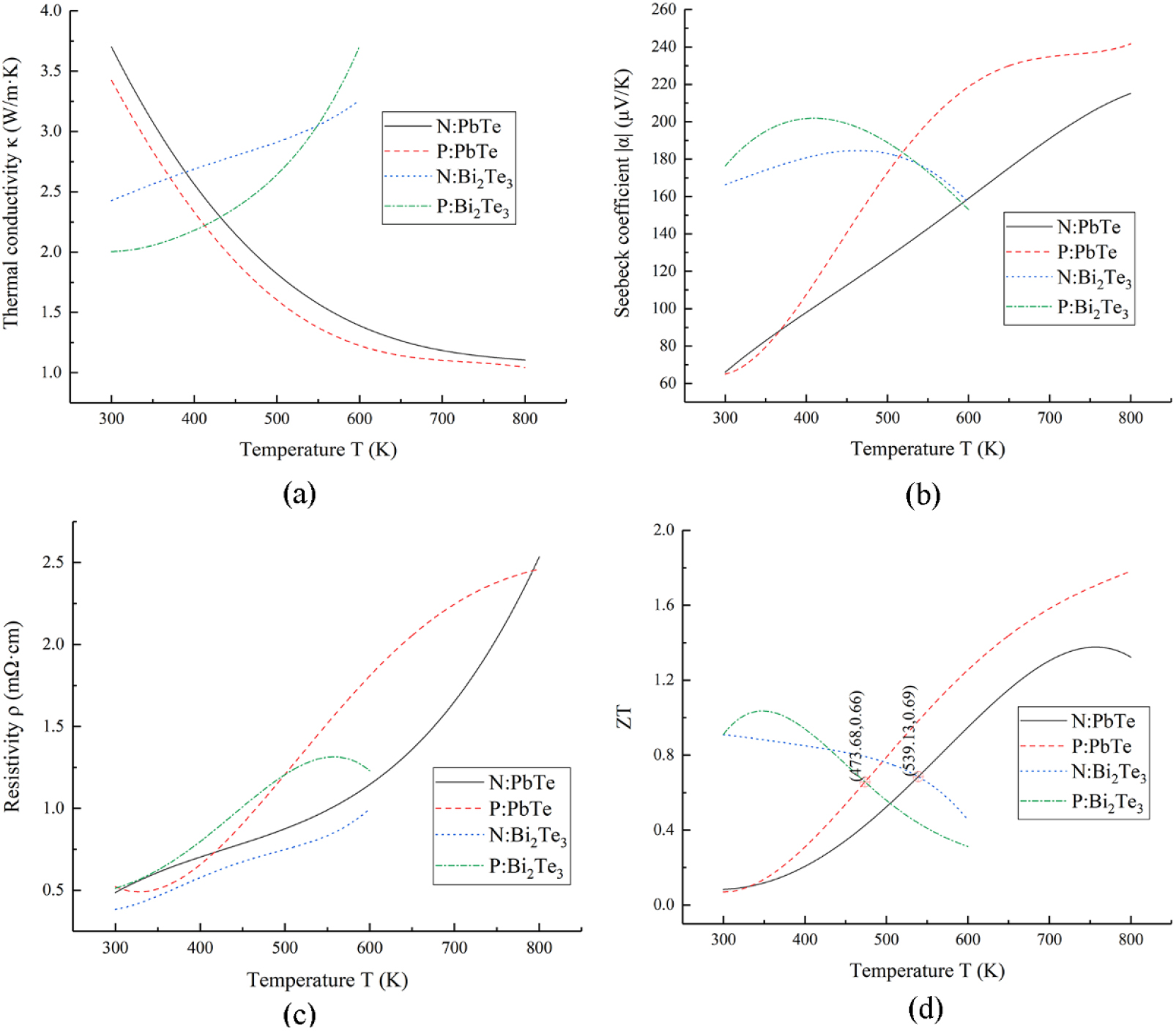
The fitting equations of the thermal conductivities of the four thermoelectric materials can be obtained by using a fitting function mode, and the relation between the thermal conductivity and the temperature can be obtained by fitting the thermal conductivity as a quartic function of the temperature, as shown in Eq. (33).
Where
Through fitting, the corresponding
When the thermal conductivity is fitted by a quartic function, the values of each coefficient corresponding to different thermoelectric materials
The relationship between the Seebeck coefficient and the temperature of the four thermoelectric materials is obtained by the same method, and the relationship is shown in Eq. (34). The value of
Where
When the Seebeck coefficients is fitted by a quartic function, the values of each coefficient corresponding to different thermoelectric materials
From the results of fitting the data, a plot of the product of resistivity
Where
The values of
When the product of thermal conductivity and resistivity is fitted by a quintic function, the values of various coefficients corresponding to different thermoelectric materials
Product of thermal conductivity and resistivity of different thermoelectric materials is fitted by a quintic function.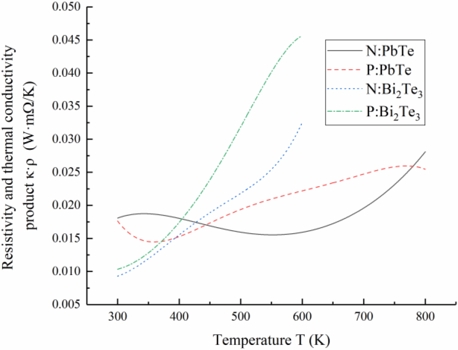
For the TTEG, based on existing products in the market, it can be assumed that the total height of the high-temperature layer and the low-temperature layer PN-type thermoelectric arms is 2 mm. The total area of the PN-type thermoelectric arms of the high-temperature layer and the low-temperature layer is equal, and the ratio of this size to the total area of the intermediate ceramic is 3.5:1. It is assumed that the sum of the cross-sectional areas of the individual PN-type thermoelectric arms in the upper and lower layers of the TTEG is 2 mm
When
According to the dimensions in Table 4, the corresponding three-dimensional model drawings are constructed for simulation analysis. The contact resistance and the effect of the outermost ceramic layer on the thermal conductivity are not considered in the software simulation. In order to ensure the accuracy of the calculation, the resistivity of the ceramic is adjusted to 100
Various performance parameters of different thermoelectric material
In the calculation process, the hot end temperature is set to 800 K and the cold end temperature is set to 300 K. The cold end of the N-type thermoelectric arm is arranged in the PN-type thermoelectric arms of the low-temperature layer is 0 mV. The hot end of the P-type thermoelectric arm arranged in the PN-type thermoelectric arms of the high-temperature layer is 0 mV. In this way, the maximum value of the simulation result is the voltage generated by the PN-type thermoelectric arms in the low temperature layer, and the absolute value of the minimum value of the simulation result is the voltage generated by the PN-type thermoelectric arms in the high temperature layer.
In this paper, the thermoelectric analysis module of the finite element simulation software COMSOL Multiphysics was used for the finite element analysis. After adding the constraint conditions according to the above requirements, the results are shown in Fig. 5.
When 
Using Eqs (21) and (23) and the data in Table 3, it can be calculated that the voltage of the high-temperature layer of PN-type thermoelectric arms is 116.749 mV, and the voltage of the low-temperature layer of PN-type thermoelectric arms is 76.908 mV. As a result of the comparison, the voltage error of the high-temperature layer of PN-type thermoelectric arms was 0.39 mV, and the voltage error of the low-temperature layer of PN-type thermoelectric arms was 0.344 mV. The error value may be caused by the following reasons: 1. In the process of calculation, the thermal resistance of the current inducer is not considered, which leads to the difference between the temperature at both ends of the PN-type thermoelectric arms and the set temperature; 2. The heat conduction process in the middle of the ceramic piece is not an ideal one-dimensional heat conduction state, resulting in ceramic piece thermal resistance being greater than the calculated results; 3. In the process of simulation calculation, the parameters are set in the form of points, not in the form of function, so there will inevitably be errors in the calculation process.
When 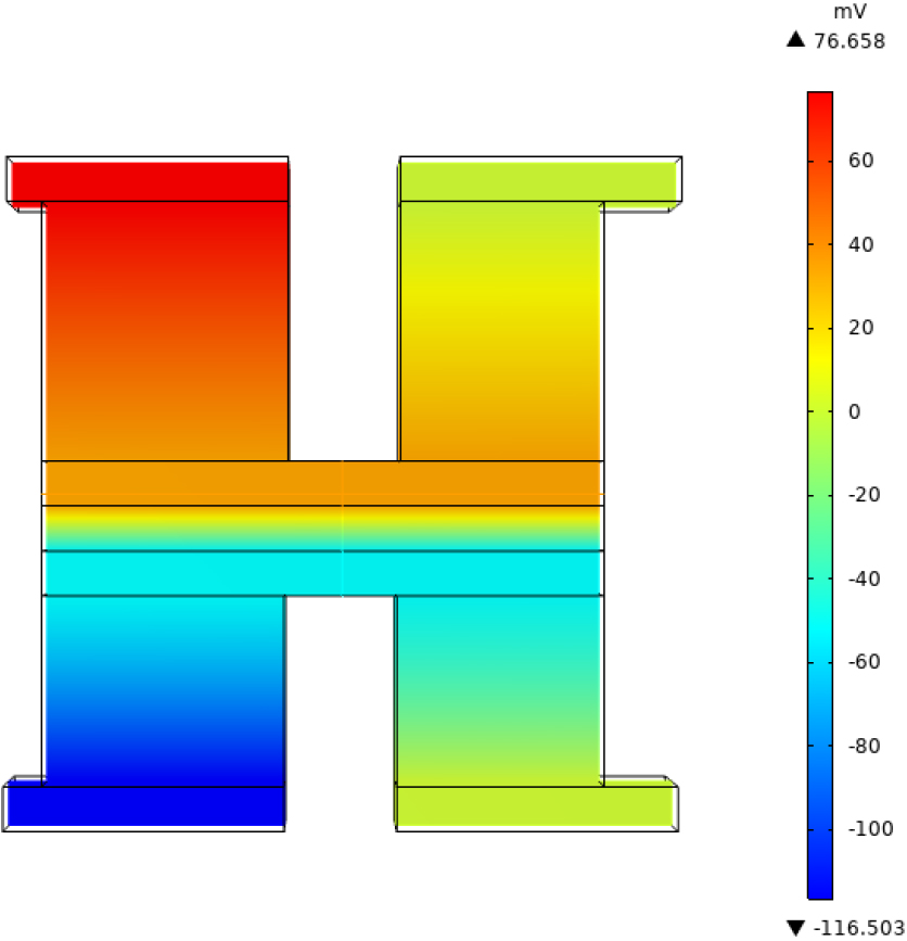
In order to verify the conjecture, the length, width and height of the intermediate ceramic can be changed to 2.5 mm, 1.0 mm and 0.2 mm. Because the area of the intermediate ceramic is equal to the area of the current inducer plate, the heat conduction process is closer to an ideal heat conduction state. The thermal conductivity of the copper material is changed to 3.9
For the TTEG, it can be assumed that the number of PN-type thermoelectric arms in the low-temperature layer is 98, the cross-sectional area of a single PN-type thermoelectric arm is 2 mm
When
As shown in Fig. 7, it can be calculated that the corresponding optimal size at the maximum output power is shown in Table 6, when
The relevant dimensions corresponding to the maximum output power of the TTEG
The relevant dimensions corresponding to the maximum output power of the TTEG
Relationship between 
The four thermoelectric materials can be used for manufacturing the STEG, and in order to make a comparison with the STEG, the size of the STEG can also be assumed to be as follows: the cross-sectional area of a single PN type thermoelectric arms is 2 mm
By further deriving Eq. (12), it can be calculated that the resistance of the P type and N type thermoelectric arm in the segmented thermoelectric generator is calculated as shown in Eq. (36).
By further derivation of Eq. (36), It can be obtained that the output power is maximum when the cross-sectional area of P-type and N-type thermoelectric arms is as shown in Eq. (37).
Finally, the voltage of the single PN-type thermoelectric arms in the STEG can be obtained by using Eqs (22) and (34), and the resistance value of the single PN-type thermoelectric arms can be obtained by using Eq. (36). So that the output power of a single PN-type thermoelectric arm can be obtained, and the output power value of the STEG can be obtained by multiplying the calculation result by the number of the PN-type thermoelectric arms contained in the STEG.
Using the obtained resistance and voltage, it can be calculated that when
The above method can be used to calculate the maximum power corresponding to the STEG and the TTEG when
Maximum output power of STEG and TTEG at different temperatures
Relationship between 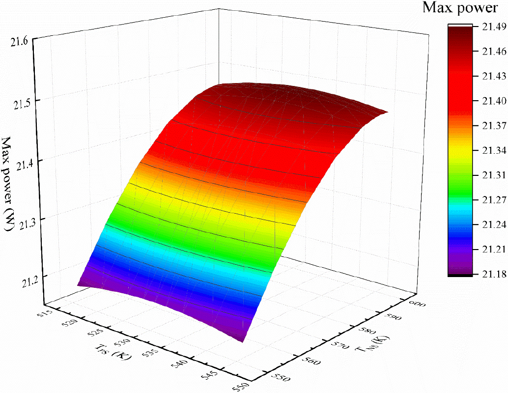
As can be seen from Table 7, under the conditions set above, when
Due to the low efficiency of the Two-stage Thermoelectric Generator (TTEG), the temperature of the cold end (
When Based on the proposed model, the maximum output power of the STEG in the same size with different materials was studied and compared by taking PbTe as the medium temperature material and Bi
In view of the author’s limited ability, the calculation process of this paper also has many deficiencies. Because the efficiency of the TTEG is very low, after the external resistance is connected, the main factor affecting the internal temperature distribution of the PN thermoelectric arm in the thermoelectric generator is the temperature of the hot end and the cold end. Therefore, in the calculation process, the temperature change inside the PN thermoelectric arm after the external resistance is ignored, and only the influence of the temperature of the cold and hot end on the internal temperature distribution of the PN thermoelectric arm is considered. Although the most important factors affecting the internal temperature distribution are considered in the process of structural optimization analysis of TTEG, the influence of some secondary factors such as Peltier effect, Thomson effect, Joule heat and other heat conduction modes between thermoelectric arms on temperature is ignored. As a result, the calculation results of this paper will be different from the actual results. Therefore, a more perfect mathematical or theoretical model should be established in the future research, and more influencing factors can be taken into account in order to obtain more accurate optimization results.
Footnotes
Acknowledgments
This work was financially sponsored by the National Natural Science Foundation of China (51879117). This work was also supported by the Guiding (Key) Project of Science & Technology Department of Fujian Province (2016H0024) and Natural Science Foundation of Fujian Province in China (2023J01146).