
Abstract
In the direction of better resolution of time lag, nonlinearity and uncertainty in the heating system, a BPNN-PID (BP neural network PID) controller is proposed in this paper. A complete heating auto-control system is designed with the experimental platform of a university heat exchange station in Zhangjiakou as the research background. The auto-control system takes Programmable Logic Controller (PLC) as the control core, uses BPNN algorithm to optimize the PID control parameters, and finally takes outlet temperature of 1# plate exchanger as the main control parameter to conduct experimental research on BPNN-PID control and single-loop feedback control respectively. The results show that compared with the single-loop feedback controller, the PID control based on BPNN algorithm has superior control quality, with shorter adjustment time, smaller overshoot, finer control accuracy and stability.
Introduction
Centralized heating is an fundamental part of people’s life in the northern part of China, and the heat exchange station, as an important part of centralized heating, is related to people’s quality of life because of the good or bad operation of its system [1]. Under the prompt progress of society and the rapid development of information technology, the traditional operation mode of heat exchange station heating system can no longer well meet the demands of modern society [2, 3]. Therefore, this paper proposes an intelligent algorithm to reasonably optimize the heat exchange station auto-control system and integrate the concept of energy conserving and surrounding protection, which can not only improve the operation efficiency and quality of heat exchange station auto-control system to a certain extent, but also improve people’s living standard.
At present, the secondary water supply of centralized heat exchange stations, as the main method used in most residential areas, still has problems such as mismatch between heat supply and demand, high energy consumption and waste of resources in operation control, so it becomes necessary to ameliorate the quality of secondary water supply [4]. In order to solve the above problems, many scholars have done a lot of research on the control of heat exchange station. In the temperature control of some heat exchange stations, heat load prediction is used to guide the heat control of heat exchange stations. Deep learning model is applied to solve the problem of short-term load prediction, so as to optimize the allocation of heating resources and reduce energy waste. Some scholars have studied the temperature control algorithm of heat exchange station, such as fuzzy control and genetic algorithm, and have made certain achievements in optimizing the control system. However, in the auto-control system of outlet temperature of 1# plate exchanger of heat exchange station as the controlled parameter, the controlled object plate exchanger has the features of sizeable hysteresis, considerable inertia, nonlinearity and variable parameters, so it is hard for the single control means to meet the control requirements, so this paper proposes the BPNN-PID intelligent control algorithm [5]. The BPNN algorithm has the capability to implement any complex nonlinear mapping, while BPNN-PID uses self-learning and self-adaptive features to realize the optimization of three control parameters: proportional, integral, and derivative, thus improving the control quality of water supply temperature, reducing energy consumption, and finally realizing on-demand heat supply [6].
Design of BPNN-PID controller
Adjusting the relationship between the three parameters of proportional, integral and derivative for purpose of achieving a good control effect in PID control, the three parameters cooperate with each other and mutual constraints, so to find the optimal combination of the three becomes a problem [7]. Using the capacity of BPNN to fit any nonlinear function, the neural network structure is established according to the actual operating characteristics of the project, and the optimal combination of proportional, integral and differential output is found through online real-time learning, so as to realize the control of PID parameters rectified by BPNN algorithm. The structure of the BPNN-PID controller applicable to this system is shown in Fig. 1, which consists of two parts,one is single-loop feedback control, the other is BPNN algorithm [8].
Structure of BPNN PID controller.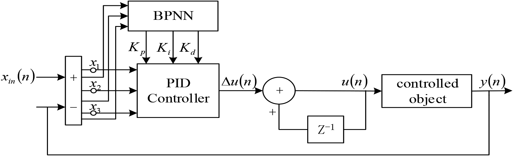
Based on existing models that perform well and through continuous experimentation, the BPNN used in this system is a 3-5-3 three-layer topology, that is, 3 input points, namely the temperature setting value r, the practical temperature output value y, and the difference value e of the above two, 5 implicit layer nodes, and 3 output points corresponding to
Neural network topology diagram.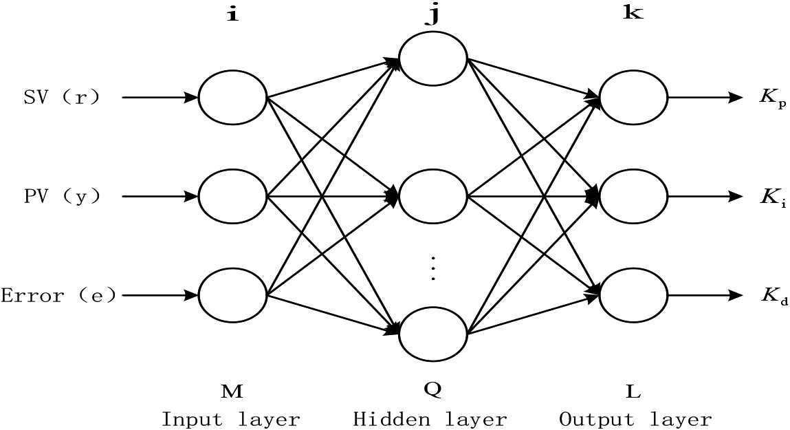
According to the calculation formula of the function signal and the error signal of the neural network, the control algorithm of the PID controller is finally obtained as:
Where,
In this thesis, the BP learning algorithm is used to iteratively correct the connection weights between neurons in each layer of the neural network, plus a global very small momentum term to make the search converge quickly [10]. Finalize the learning algorithm for the output layer of the BPNN:
Similarly, the learning algorithm of the hidden layer of the neural network can be obtained
Project introduction
The project is located in the Northern Region Clean Heating Training Base of Hebei University of Architecture. The platform uses 2 electric hot water boilers to simulate the primary heat source to heat the whole room, and 2 refrigeration units to simulate a small number of secondary users, in addition to 2 plate exchangers, 4 circulating pumps, 2 make-up pumps, 6 electric control valves, sensors and other equipment, of which the make-up pumps and some circulating pumps are used for one and one standby. Circulation pumps are frequency-controlled, plate exchanger using water – water heat transfer, while equipped with a complete operating monitoring screen, its process and monitoring principles are shown in Fig. 3.
Process flow and monitoring schematic.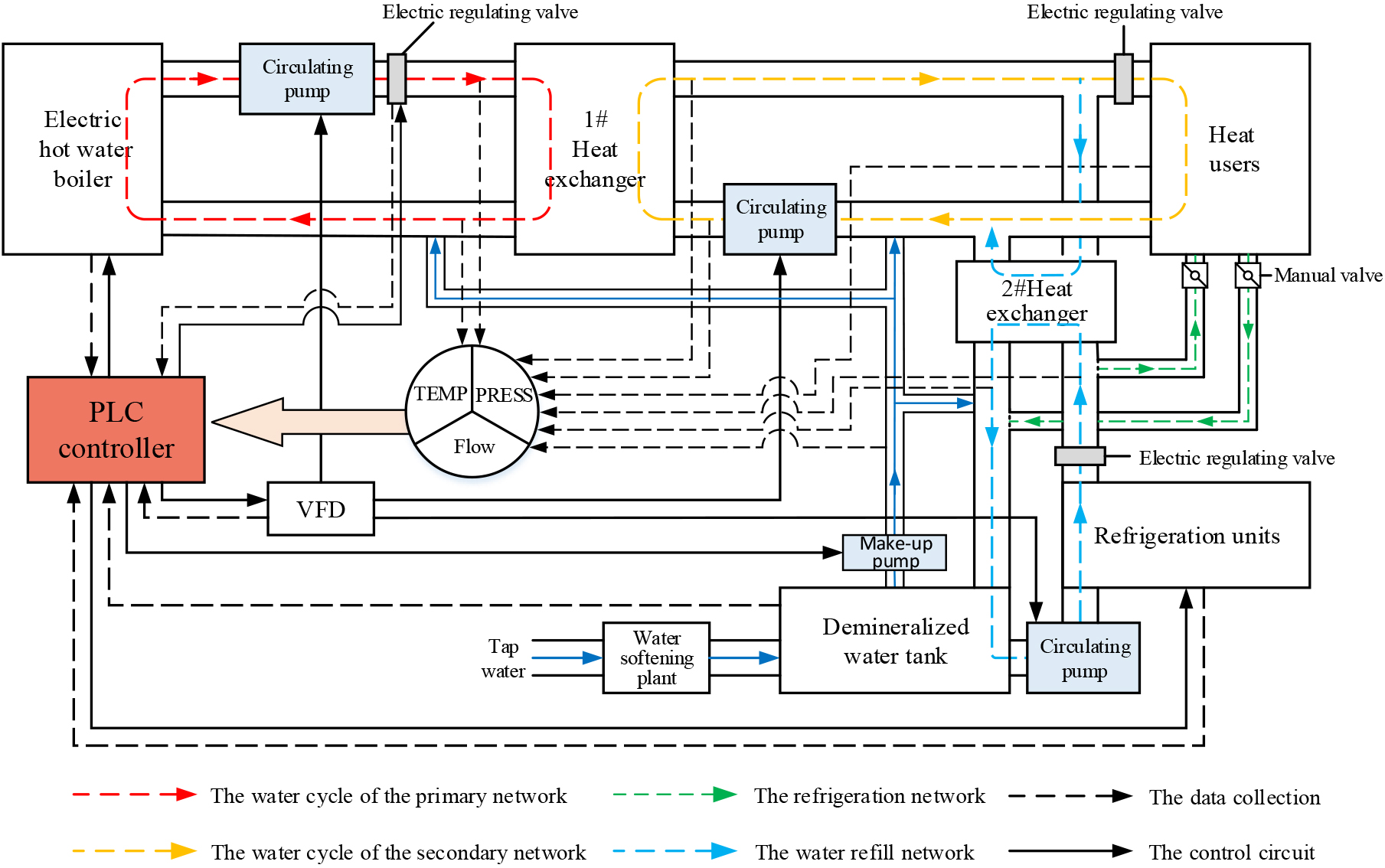
The platform can achieve two operating conditions, one is heating in winter and the other is cooling in summer. Which winter heating, electric hot water boiler simulated heat source, high-temperature hot water through the primary heat network to the heat exchange station, the primary heat network of high-temperature hot water through the plate exchanger and secondary heat network of circulating water for heat exchange, the water from the #1 plate exchanger two ways, one way through the water distributor to the radiator and fan coil to the room heating, the other way to #2 plate exchanger, and the cold water out of the refrigeration unit is heat exchanged in #2 plate exchanger, dissipate less part of the heat, the two ways of the return water convergence through the decontaminator, through the circulation pump and then unified back to #1 plate exchanger.In summer refrigeration, close the heating pipeline path, refrigeration unit work, the use of fan coil to achieve refrigeration function.
Control of outlet temperature of 1# plate exchanger
The control of outlet temperature of 1# plate exchanger is a crucial link, the quality of which not only affects the heating quality, but also relates to the issue of resource saving [11, 12]. The system adopts BPNN-PID controller to regulate outlet temperature of 1# plate exchanger. The system compares the actual outlet temperature of 1# plate exchanger collected by the temperature sensor with the set value, if there is a deviation between the two, the controller will regulate the primary network electric regulating valve on the basis of the difference value, and change the primary network water supply flow by changing the opening degree of the primary network electric regulating valve, and then maintain outlet temperature of 1# plate exchanger near the set value [13]. The construction of control is displayed in Fig. 4.
Block diagram of the auto-control system of secondary water supply temperature.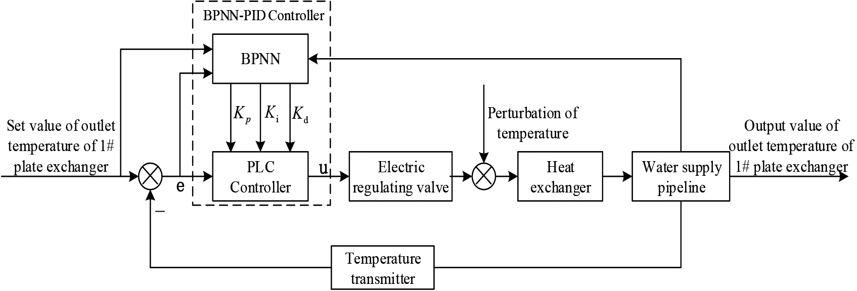
Structure diagram of the control of secondary network circulation pump.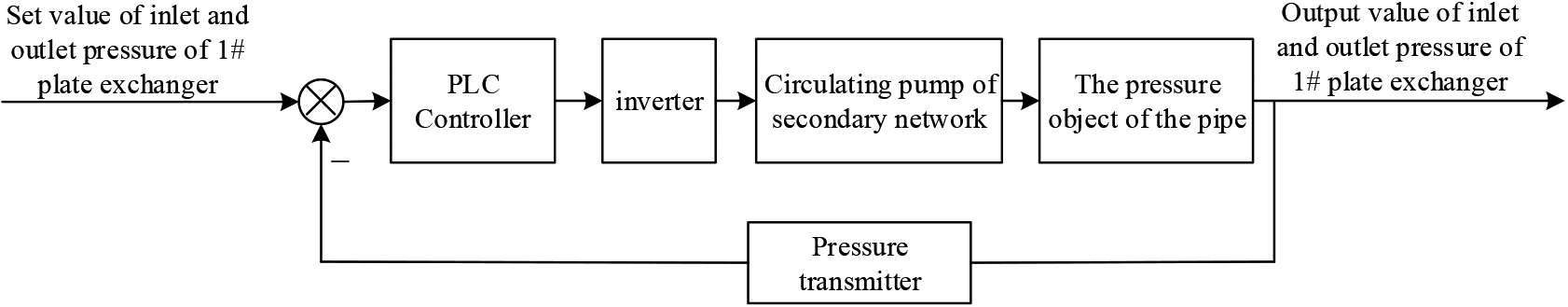
The system secondary network circulation pump control is used for regulating the flow of circulating water in the network, using frequency control, according to the set value of pressure difference between inlet and outlet pressure of 1# plate exchanger, using the single-loop feedback controller to adjust the frequency of the inverter and then adjust the working frequency of the circulation pump, to achieve control of the difference between inlet and outlet pressure of 1# plate exchanger, to meet the secondary network heating water circulation. In addition, the system is designed with a manual mode, in which the operator can start/stop and set the frequency manually through the touch screen or the buttons on the control cabinet. The variable frequency technology can well solve the problems such as poor heating effect caused by too small differential pressure and safety accidents caused by too large differential pressure, and its control structure is displayed in Fig. 5.
Control of charge pump
The secondary return water pressure is kept constant through the adjustment and control of the charge pump. When the actual secondary return pressure value detected by the pressure sensor is more inferior than the set point, the make-up pump will be started automatically; when the obtained secondary return pressure is upper than the upper limit of return pressure, the make-up pump will stop running.
Modeling of BPNN-PID control algorithm
The set value of outlet temperature of 1# plate exchanger of the heat exchange station is used as the system input
Dynamic structure diagram of outlet temperature of 1# plate exchanger auto-control system.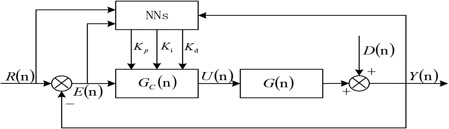
Step response curve of outlet temperature of 1# plate exchanger.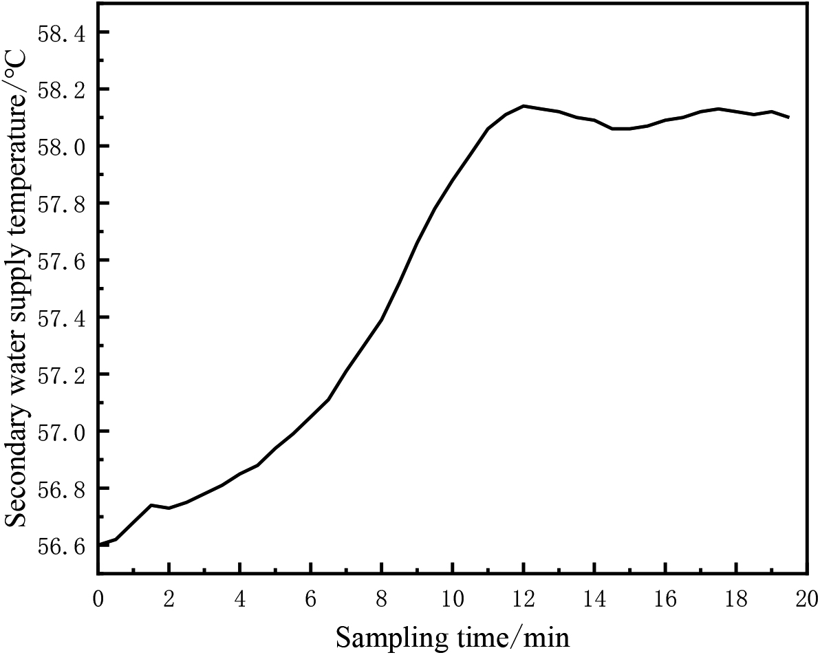
Because the temperature auto-control system of the heat exchange station is a complex and variable nonlinear system in actual operation, this paper uses the system identification method to build the mathematical model of outlet temperature of 1# plate exchanger [14]. Perform the step response curve test under single-loop feedback control and determine the system model based on the response curve obtained from the actual operation data. The experimental data is selected from the measured data on December 25, 2021, and the step response curve of the system is displayed in Fig. 7. From the curve, it can be derived that the temperature control has a time delay phenomenon in the actual industrial process, assuming that the system is a first-order inertia
Using the theoretical calculation method to find
Solve
Solve
By normalizing
Take 2 points in the step response curve, whose horizontal coordinates are
To make the data
Where,
Based on the process demands of this heat exchange station, the slave computer uses PLC to control the field equipment, and the upper computer uses HMI embedded touch screen and SCADA to realize local and remote monitoring [16]. It is a heating system with two plate exchangers, four circulating pumps, two charge pumps, six electric regulating valves, and on-site equipment such as temperature, pressure, level sensors, electromagnetic flow meters, frequency converters, decontaminers, softening tanks, and electric meters. The data parameters such as T (temperature), P (pressure), F (flow-rate), softening tank’s level and frequency of inverter in the heat exchange station are collected in real time and uploaded to the PLC and the host computer, and the control of electric regulating valves, circulating pumps, charge pumps and inverters is realized through the calculation and analysis of BPNN-PID controller. Through the host computer, it can store and monitor the operation status of field equipment, data parameters and heat network operation conditions in the heat exchange station.
The auto-control system adopts SIEMENS S7-200 SMART PLC as the control core. According to the control scheme of the heat exchange station heating automatic auto-control system and the actual number of monitoring points, and to ensure that the number of PLC terminals accounts for 10%–20% of the total number of points, the CPU module is SR60 (36 input and 24 output). As the system requires more analog, so the expansion of analog modules, the choice of four EM AE08 modules and two EM AQ04 modules. In addition, a SB CM01 signal board is provided for RS485 communication to connect the inverter, electric hot water boiler and refrigeration unit.
Address allocation table of the system’s I/O points
Address allocation table of the system’s I/O points
Flow chart of auto-control system of heat exchange station.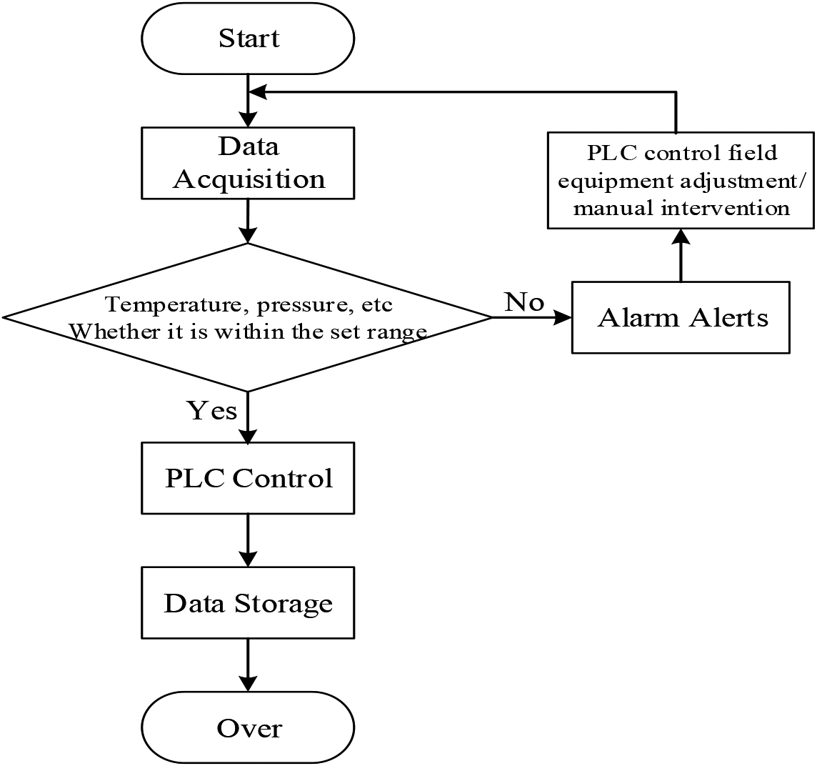
Flow chart of control program of secondary water supply temperature.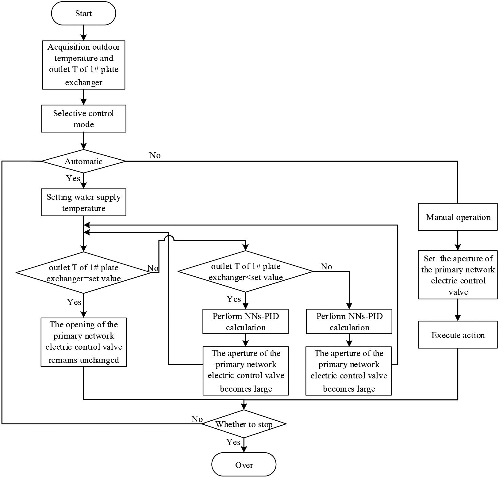
Flow chart of BPNN-PID control algorithm.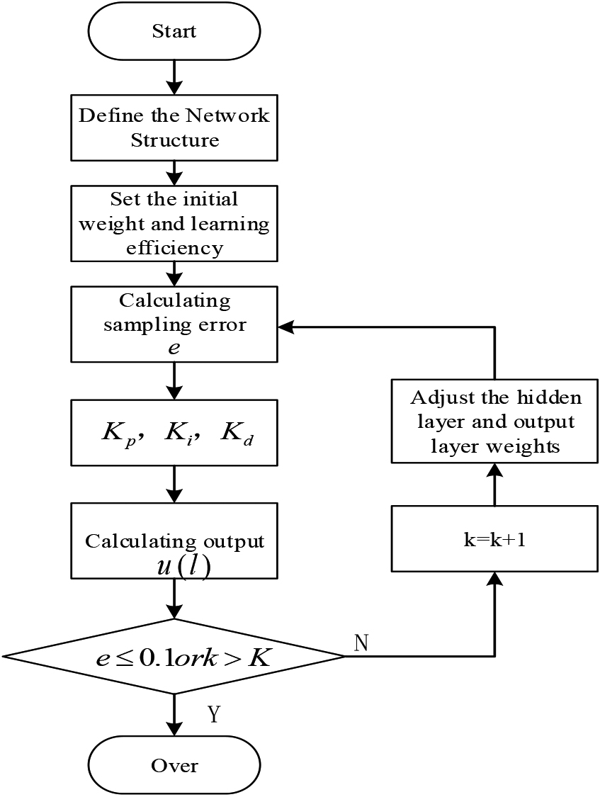
Program of the temperature control.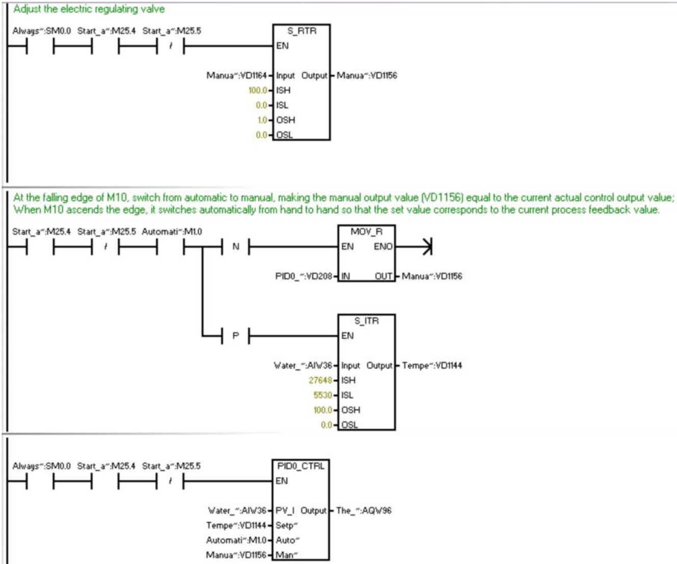
Main interface of heat exchange station operation management.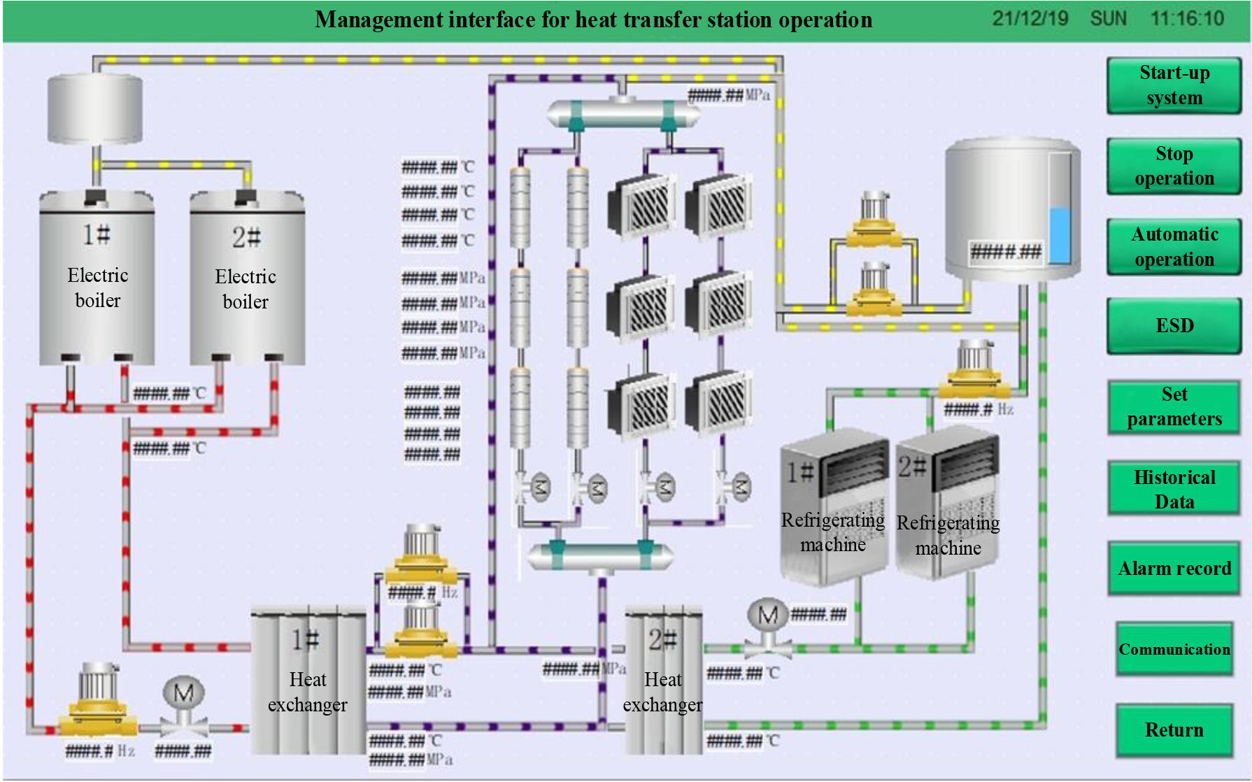
The interface of control mode selection and parameter setting.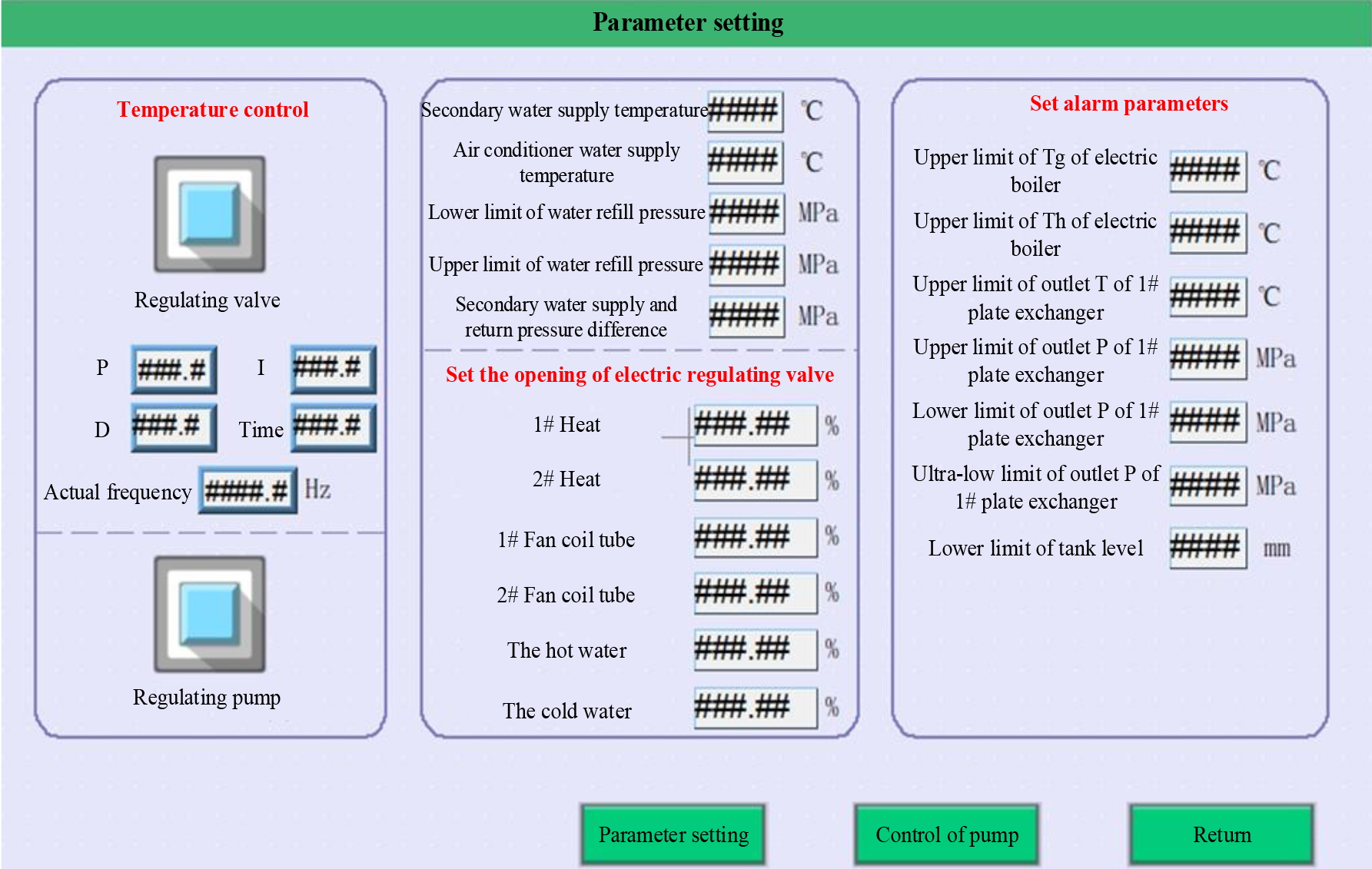
Comparison of the control effect of secondary water supply temperature.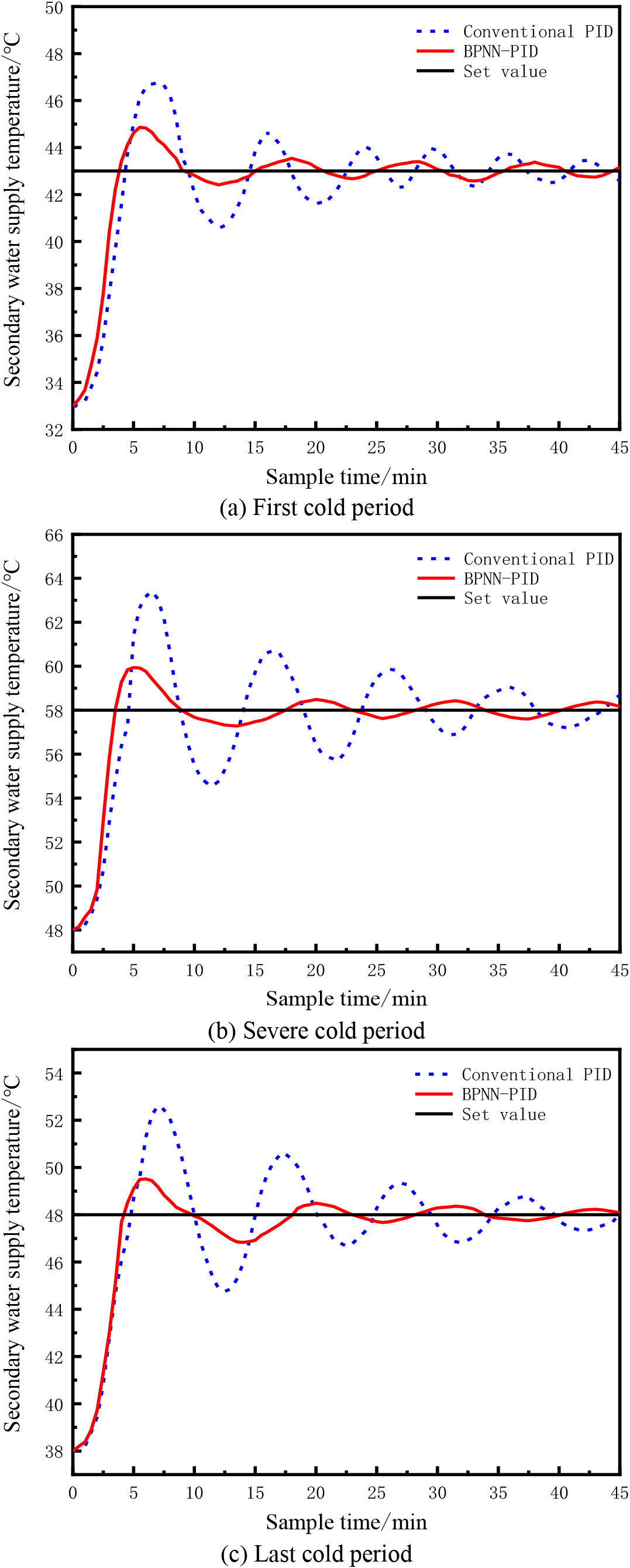
The digital input (DI) module of this heat exchange station heating auto-control system is mainly used for the feedback of circulating pump, charge pump and inverter operation status and fault status, as well as the signal input of system start, stop and operation mode selection; the digital output (DO) module is mainly for the start and stop control of circulating pump and charge pump, in addition to some indicator outputs such as comprehensive alarm. Analog input (AIW) module is mainly used for data acquisition such as supply and return water network temperature, pressure, flow signal, make-up water tank level signal, outdoor temperature signal, and feedback signal of electric regulating valve opening; analog output (AQW) module is mainly used for giving signal of electric regulating valve opening. The system I/O address assignment is shown in Table 1. The settings of electric hot water boiler, refrigeration unit and inverter parameters are transmitted through RS485 communication.
After completing the hardware frame of this system and the construction of the field equipment, software design and implementation are required. The main workflow of the heat exchange station heating automatic auto-control system is displayed in Fig. 8, according to the program to achieve the release of control commands, data storage, management and analysis, etc.
The system program mostly includes 5 subroutines, namely data acquisition subroutine, communication subroutine, automatic heating subroutine, fault handling subroutine and safety protection subroutine. The data acquisition subroutine is the basis of the whole program, mainly providing data support for other subroutines. On the one hand, the collected data provides control parameters and feedback for the automatic heating of the system through data processing, so that the auto-control system can be precisely regulated. On the other hand, it is used for system fault self-diagnosis, which will alarm and indicate the error type when abnormal conditions are found. If it is a serious error, it will automatically stop the operation, which greatly improves the safety of the system.
In the automatic heating subroutine to realize the control of electric regulating valve, circulating pump and make-up pump, according to the set value of each parameter, the collected data of temperature, pressure and flow of primary and secondary networks are transmitted to the PLC control cabinet of heat exchange station and the upper computer. After PLC calculation and analysis, PID control technology is used to achieve precise regulation and control of electric regulating valve, circulating pump and make-up pump, to achieve stability and optimization of outlet temperature of 1# plate exchanger and constant outlet pressure of 2# plate exchanger, to improve heating quality.
Control program design of outlet temperature of 1# plate exchanger
There are two ways to control outlet temperature of 1# plate exchanger in this system, one is manual control, directly set the aperture of the primary network electric regulate valve to change inlet heat medium flow of 1# plate exchanger, and then affect the temperature inside the plate exchanger, so as to realize the change of outlet temperature of 1# plate exchanger; another one is auto-control, according to the actual temperature data collected and the set value for comparison, using BPNN-PID intelligent control regulation to find the optimal control parameters, make corresponding countermeasures and correct the aperture of the primary network electric control valve in real time, so that outlet temperature of 1# plate exchanger is always stable near the set value [17]. The program control flow is shown in Fig. 9.
The program is written in STEP 7-MicroWIN SMART software using the ladder language. First, in the data acquisition subroutine, we will convert the analog input signals such as T, P, F and valve opening, etc. to real numbers in the corresponding ranges that we can conveniently use S-ITR instruction and then store them in VD1000
The learning phase of the BPNN is implemented in the upper computer using C
Upper computer design
In addition to the programming design of the slave PLC, the monitoring design of WINCC is also important for the heat exchange station heating auto-control system [19]. The design of this paper adopts Velcom touch screen to achieve the monitoring and auto-control of field operation condition. The main interface of operation management reflects the current operating conditions, and the control interface can be used to select the operation mode and set the control parameters, and also has historical data curves and alarm records, etc. The interface of the upper computer design is shown in Figs 12 and 13.
Experimental results and analysis
Control effect
Experiment of single-loop feedback control and BPNN-PID control for water supply temperature of heat exchange station, and the temperature data of three stages of early cold period, severe cold period and late cold period were selected for comparison and analysis [20]. The black line in the experimental curve indicates the temperature setting value, the red line shows the temperature measurement value of BPNN-PID controller, and the blue line indicates the temperature measurement value of single-loop feedback control.
For the BPNN control algorithm, set its learning rate to 0.2, the inertia coefficient is selected as 0.01, the number of chaos between [
Analysis of performance indicators
The graph shows that the PID control rectified by the BPNN algorithm shows superior control quality than the single-loop feedback control, and the BPNN-PID control shows better stability than the single-loop feedback control in all three operating conditions, and the accommodation time is shorter and the overshoot is smaller. Toward more accurately compare the control effect of the two controllers for the heat exchange station heating system, the relevant performance indexes were compared and analyzed, and the results are displayed in Table 2.
Analysis of performance indicators
Analysis of performance indicators
In summary, in the heat exchange station heating auto-control system, the use of BPNN-PID controller to realize the regulation and control of outlet temperature of 1# plate exchanger can effectively reduce the valve opening adjustment frequency, further reduce the time lag of temperature changes, so that outlet temperature of 1# plate exchanger reaches the set value as soon as possible. At the same time, BPNN-PID controller is significantly superior than the single-loop feedback controller in terms of system oscillation amplitude, reducing overshoot, improving control accuracy and stability, and showing ideal control effects in both dynamic and static performance [23]. In this system, the control accuracy of the step response curve under the BP neural network PID control algorithm is within the range of
This paper propose a BPNN-PID intelligent control for the nonlinearity and large lag of the controlled object in the central heating system, and use the BPNN self-learning ability to regulate the control modulus in real time to obtain the optimal control effect [24, 25]. The optimal control effect is to achieve the control objective: improve the control accuracy of water supply temperature (