
Abstract
This paper addresses prevalent issues of suboptimal compatibility between the heating exchanger and the thermal storage unit, poor safety performance, and overall insufficient heat exchange efficiency within the application of heating exchangers in electric heating solid energy storage heating systems. Experimental testing and numerical simulation studies were conducted. The research investigates the effect of the temperature of inlet air as well as velocity on the heat exchange performance of the heating exchanger as well as temperature variations of single-row heat pipes. Drawing upon these change patterns, an optimized heating exchanger structure is proposed and subsequently investigated through optimization simulation studies. The study results indicate that the best overall optimization effect is achieved with a heating exchanger arranged with finned tube combinations of 4 mm in two rows, 6 mm in two rows, 8 mm in two rows, 10 mm in two rows, 12 mm in two rows, and 14 mm in ten rows arranged successively from front to back. When the heating exchanger’s inlet air speed is relatively high, this combination’s heat exchange capacity surpasses the original structure. Additionally, the uniformity of air-side temperature drop improved by 44.89%, while the finned area was reduced by 25.62%.
Keywords
Introduction
With rapid economic growth comes inevitable ecological challenges. China firmly adheres to the basic national policy of environmental protection and resource conservation. In response to the rising trend of total energy consumption, there is ongoing commitment towards energy saving and emission reduction goals, persistently optimizing the energy supply structure. As a result, coal, gas, oil, nuclear, new energy, as well as renewable energy have become integral components of the energy supply chain. “3060” was proposed by the Central Committee of the Communist Party of China and the State Council in September 2020, aimed at actively transforming energy use and breaking away from fossil fuel dependence [1, 2]. Electric heating solid energy storage technology, guided by societal demands, replaces coal heating with a clean, pollution-free heating method, effectively alleviating the fossil energy crisis brought about by heating. Moreover, solid energy storage technology’s load levelling can effectively improve the equipment utilization rate of the power system and stabilize its operation. Currently, the technology of electric heating solid energy storage heating has achieved scaled application in China.
However, due to the late start of solid electric storage technology in China and the absence of uniform national standards, the quality of solid energy storage equipment varies and the efficiency of electric heating solid energy storage heating systems is relatively low. The heating exchanger, as an important link in the heating system, can transform high-temperature heat within the energy storage unit into abundant low-temperature heat energy, which is then safely distributed to end heat users. According to a substantial amount of data from solid energy storage heating projects, the most common heating exchanger used in these systems is a finned tube heating exchanger. Energy storage units, however, vary greatly in their temperature of outlet air and velocity due to heating duration and operational adjustments, resulting in a low degree of compatibility between the energy storage unit and the heat exchange device. To meet the heating demand of end users, manufacturers typically opt to enhance the area of the heating exchanger that is used for heat exchange so as to ensure system operation, which subsequently raises equipment costs. Furthermore, the heating exchanger’s performance is subpar during system operation. The temperature difference between the secondary side supply water and the secondary side return water is much lower than the design temperature difference. To increase heat transfer, manufacturers often resort to increasing the primary side air speed or the secondary side water flow rate, which further increases the system’s operational costs.
As an irreplaceable crucial component within the heating system, the temperature of supply air and velocity of the heating exchanger’s primary side are constantly changing, presenting a stark contrast with the stable heating parameters of traditional heating systems. Therefore, the compatibility and safety between the heat exchange device and the heating system contribute significantly to enhancing the whole operational efficiency of the heating system. Optimizing the application of heating exchangers in solid energy storage heating systems based on electric heating is vitally important for the safe and efficient operation of the overall heating system.
Electric heating solid energy storage heating system and heat exchange device
Principles of operation and system design
The solid energy storage for electric heating primarily comprises four parts: the heat source device, heat exchange device, air system, and water system. Figure 1 illustrates the principle of its heating system.
The solid energy storage unit for electric heating chiefly capitalizes on the principle of differing peak and off-peak electricity prices to complete the heat storage and release process. During off-peak periods, the energy storage body, constructed from heat storage bricks, transforms electrical energy into thermal energy via embedded electric heating wires, continuously storing heat until it satisfies the daily heating demand of the system. Upon completing heat storage, the energy storage body transitions into the heat release and heating phase. The fan is activated, applying wind pressure via a high-temperature resistant variable frequency fan. The circulating air flow absorbs the heat stored in the energy storage body through designated air ducts, then enters heating exchanger with finned tubes. Here, heat is transferred and released to the secondary low-temperature water via the heat pipe wall. The cooled air returns to the interior of the energy storage body via the air duct, completing the primary side circulation; the secondary side’s low-temperature water absorbs the heat released by the hot air. Under the pressurization of the circulating water pump, heat is released to end-users through terminal radiators, thereby completing the heating circulation process of the system [3].
Schematic diagram of the system for heating a solid energy storage unit using electric heat.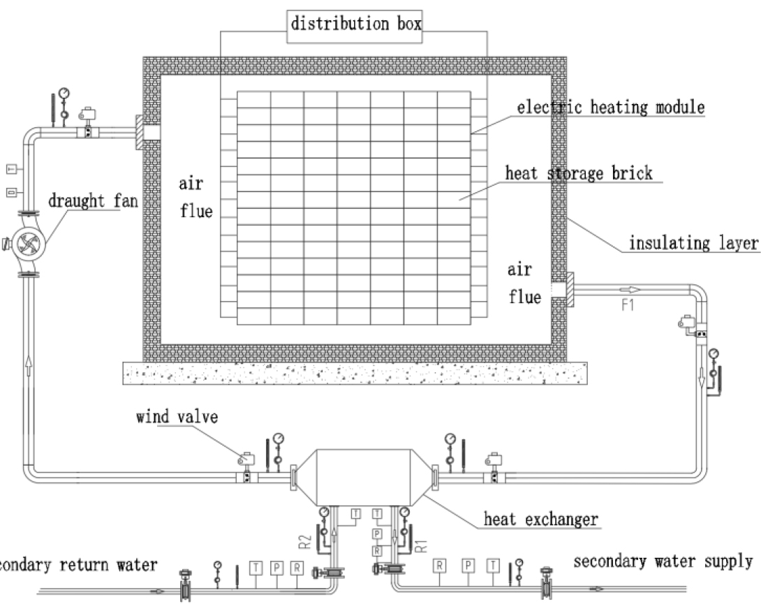
Finned tube heating exchangers have historically been predominantly utilized in surface cooling or waste heat recovery projects, where heat transfer quantity was the sole evaluation criterion. However, this conventional single criterion is not wholly applicable to finned tube heating exchangers within solid energy storage heating systems. For practical application in solid energy storage heating projects, a comprehensive consideration of various aspects such as heat transfer quantity, heat exchange efficiency, and safety performance of the heating exchanger is essential for maximizing improvements in the operational performance of the heating system [4].
(1) Heating load
The use of a heating load evaluation for assessing the performance of the heating exchanger ensures that the system receives the necessary amount of heat. A heating exchanger’s heat transfer capability can be intuitively determined by calculating its heat load. In the event that the terminal heating load is less than the amount of heat required, there is insufficient heat storage in the energy storage body, which necessitates supplementary heating.
(2) Heat exchange efficiency
Efficacy of a heating exchanger in terms of thermal efficiency is a reflection on its heat exchange performance,gauged through the quantity of energy utilization. Given a constant provision of thermal energy from the hot fluid, measures such as enhancing the insulation of the heating exchanger and minimizing thermal dissipation can be adopted to augment thermal efficiency, thereby maximizing energy utilization.
The variables in this context are represented as follows:
(3) Temperature change non-uniformity coefficient
The temperature non-uniformity coefficient is introduced utilizing the principle of relative average deviation. This dimensionless parameter, proposed for tube row heat exchange in a heating exchanger, reflects the dispersion level between the proportion of medium temperature change as high-temperature air sweeps across a single row of tubes in relation to the direction of the gas flow as well as the temperature difference.
Here,
A higher
Objective of the experiment
This experiment aims to investigate the heat exchange performance of the finned tube heating exchanger in the heating system by modulating the heat supply parameters of the heating exchanger while maintaining a constant water supply flow rate on the secondary side of the heating exchanger, changing the amount of operational fans, and altering the fan frequency. As a result, it is feasible to measure the heating exchanger’s intake and outlet temperatures as well as the flow rate data, confirming the validity of the physical model and boundary conditions used in the numerical simulation [5].
Experimental setup
This experiment was conducted on the solid energy storage test platform located in the underground boiler room at the Solid Energy Storage Heating Technology R&D Base in Zhangjiakou City, Hebei Province. The underground boiler room has an area of 20.3 m
The test platform provides heating for an office building with a construction area of 10,000 square meters. The heat index of the heating area is 65 W/m2, and based on the heat load calculation formula
Experimental plan
The experimental test content mainly includes two aspects:
(1) Heating exchanger air volume test
The wind speed at the heating exchanger intake may be changed by modifying the fan frequency, the amount of operating fans, and the amount of operating heating exchangers. An airflow sensor is used to measure and calculate the air supply volume of a single heating exchanger.
(2) Heating exchanger performance test
The principal side of the heating exchanger’s heat supply may be altered by varying the fan frequency and amount of active fans. This thus makes it possible to modify the supply and return water temperatures on the heating exchanger’s secondary side. Calculations based on measurements from thermometers and flow meters positioned at the heating exchanger’s input and exit may provide pertinent experimental data.
Test outcomes and assessment
Heating exchanger air volume test
This test altered the airflow by changing the amount of operational fans and their operating frequency, measured using an airflow sensor. Assessment of the airflow test information revealed that when the same amount of fans and fan frequency were employed, the single heating exchanger airflow varied between operating one and two heating exchangers, with the total airflow being greater when operating two heating exchangers simultaneously. From an energy-saving perspective, the same heating exchanger air supply volume could be achieved with a lower fan frequency when running two heating exchangers, resulting in greater electrical energy savings.
Heating exchanger performance test
In this test, we calculated to guarantee a certain end-point heating load while observing the temperature and flow rate of the return water on the secondary side. By modifying the airflow by altering the fan frequency as the supply air temperature fluctuated, the heating exchanger’s heat supply volume was adjusted. Following an analysis of the interactions between the heating exchanger’s intake air temperature, airflow, heat supply of the air and water, and heat exchange efficiency with heating time, the following results were drawn:
Regardless of the initial average brick temperature of the storage body being high or low, during the heating period, the stored heat in the storage body gradually decreases, and the exit air temperature of the storage body, i.e., the heating exchanger’s temperature of inlet air, shows a steady declining trend. The exit air temperature is related to the airflow; adjusting the fan frequency and increasing the airflow can slightly increase the heating exchanger temperature of inlet air in a short time but does not affect its declining trend.
Aside from the heating exchanger temperature of inlet air, the main influencing factors of the heating exchanger heating load also include the airflow. Increasing (or decreasing) the heating exchanger airflow will cause the heat supply of the air and the heat supply of the water of the heating exchanger to increase (or decrease) correspondingly. Because the heating exchanger heat exchange system itself is a thermal inertia system, its heat regulation has a temporal nature. In particular, the adjustment of the heat supply of the secondary side water requires a longer response time, leading to considerable changes in the heating exchanger efficiency values. Initially, when the airflow is adjusted, the heat supply of the primary side of the heating exchanger changes instantly, but the response time of the secondary side is longer, with its heat change showing no significant change in a short time. This leads to an immediate significant decrease (or increase) in heat exchange efficiency after the airflow is increased (or decreased). Once the heat supply adjustments of the heating exchanger’s primary and secondary sides have fully responded, the heating exchanger efficiency subsequently resumes a stable numerical change.
The efficiency of the heating exchanger is not a stable value, and the heat exchange efficiency is influenced by numerous parameters including the supply air’s temperature, volume of air supply, temperature of inlet water, and water flow rate [6, 7, 8]. During the period of stable change of the heat supply parameters of the heating exchanger in the experiment, the heat exchange efficiency mainly ranged between 60%–80%. The heat exchange efficiency can reflect the heat dissipation loss of the heating exchanger in a relatively intuitive way, indicating that the overall heat exchange efficiency of the heating exchanger in this test is relatively low, necessitating the implementation of certain measures to enhance heat exchange efficiency.
Analyzing the changes in temperature of the exit air and temperature of the exit water at various average initial brick temperatures of the heat storage body reveals that, regardless of how the temperature of inlet air of the heating exchanger changes, the return air temperature of the heating exchanger is always slightly higher than the water supply temperature on the secondary side of the heating exchanger, and the temperature difference is significant. When this is combined with the prior examination of the variations in heat exchange efficiency of the heating exchanger, it is clear that the heat exchange efficiency of the test item, the finned tube heating exchanger, is poor. The heating exchanger’s return air temperature and the water supply temperature on the secondary side are similar due to an excess of finned tube arrays in the heating exchanger, causing the tube arrays in the latter part of the heating exchanger shell to exchange very little heat or even fail to perform effective heat exchange. This has resulted in high energy waste and poor heat efficiency. The heating exchanger performance test experiment thoroughly reveals that the heating exchanger’s tube array construction is not logical, and the heating exchanger structure has to be modified to increase the heat efficiency of the finned tube and decrease energy waste.
Simulation study
Control equations
The fluid flow in the model generated in this research follows the laws of mass, momentum, and energy conservation, satisfying the criteria of an incompressible viscous fluid. The following are the particular forms of its control equations:
(1) Equation of Mass Conservation
For incompressible fluid, the density
(2) Momentum Conservation Law
(3) Energy Conservation Equation
In the equation,
The heating exchanger model was constructed based on the experimental object from the previous chapter. The main structural parameters are as follows: the finned tube base tube has an inner diameter of 32 mm and an outer diameter of 38 mm, made from carbon steel with a carbon content of 1%; the fins are 14 mm high, 0.4 mm thick, spaced 3 mm apart, with an effective heat exchange length of 840 mm, and made of aluminum; there are 20
Due to the large amount of heat pipes as well as fins in the finned tube heating exchanger, and the fin dimensions being relatively small compared to the overall structure, conducting a mesh division on the whole would not guarantee the quality of the mesh division and would make the computation process exceedingly complex. Hence, simplification of the heating exchanger model is necessary.
Flow between pipe rows when inlet wind velocity v 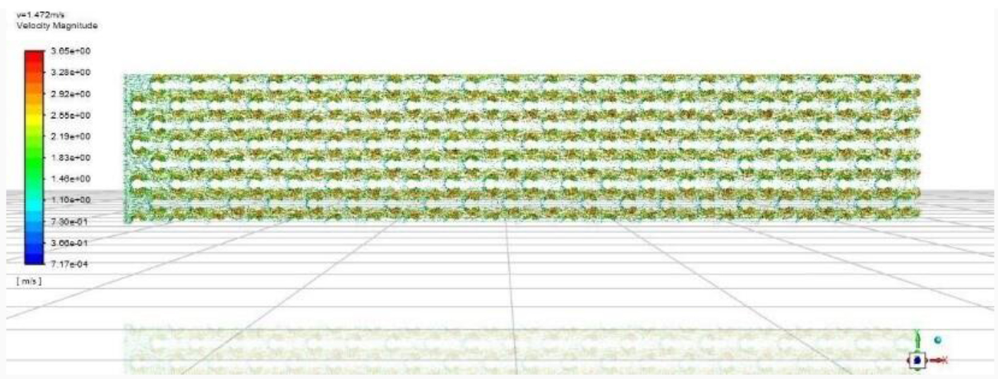
3D model of a heating exchanger.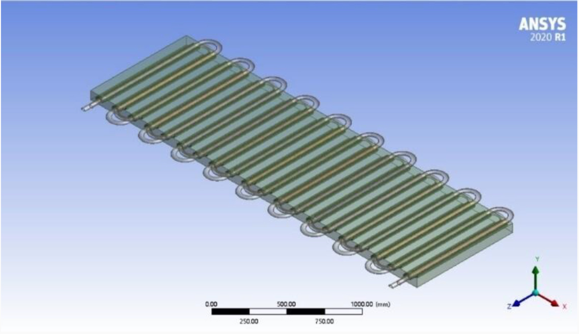
As depicted in Fig. 2, for heat exchange simulation studies of the heating exchanger, due to the periodic arrangement of the finned tube, when the air inflow on the windward face of the tube row is regarded as uniform flow, the fluid flow between the finned tube rows is similar and has a periodic flow rule. Hence, it is possible to take the upper and lower halves of two horizontal rows of finned tubes and the airflow channel between the tube rows as the research object [9]. The heating exchanger model can be seen in the image above.
This study employs ANSYS software to establish the mathematical and physical model of a heating exchanger and to segregate the model into computational grids. To simplify the computational process, densification of the grid partition is implemented in the vicinity of the fin-fluid interface, while the grid for the air-fluid and pipe-internal water-fluid can be proportionally expanded. In order to ensure the quality of the partitioned grid and enhance the accuracy of numerical computations, a quality check of the grid parameters is conducted prior to numerical resolution, guaranteeing a grid aspect ratio within 5:1, and the skewness should not exceed 0.95.
In this study, the model is simulated using FLUENT. Air-fluid’s external surface and the protruding exterior surface of the heat pipe within the air-fluid domain are considered to be adiabatic walls (Heat flux
Physical properties of various materials
Model of a heating exchanger from the top view.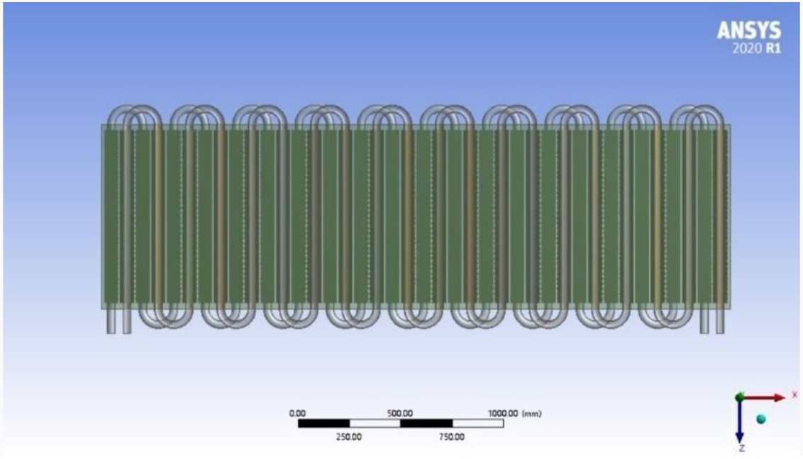
We shift our focus towards the validation of the established mathematical and physical models. To evaluate the precision of these models, we selected ten data sets from the relatively stable experimental data, as illustrated in Table 2. By defining the input and output parameters of the primary and secondary sides of the medium in the heating exchanger, we based our definitions on the experimental data, which included the inlet and outlet air temperature, airflow, inlet and outlet water temperature, and water flow rate. Our validation approach involved conducting simulations, followed by a comparison of the numerically simulated data with the experimental measurements. The results of this comparative study are depicted in Fig. 5.
Ten groups of experimental data selected for detailed operating parameters
Ten groups of experimental data selected for detailed operating parameters
Comparison between simulated and experimental values of heating exchanger. a. A comparison of the outlet air temperature of the heating exchanger based on experimental and simulated data. b. A comparison of the outlet water temperature of the heating exchanger based on experimental and simulated data.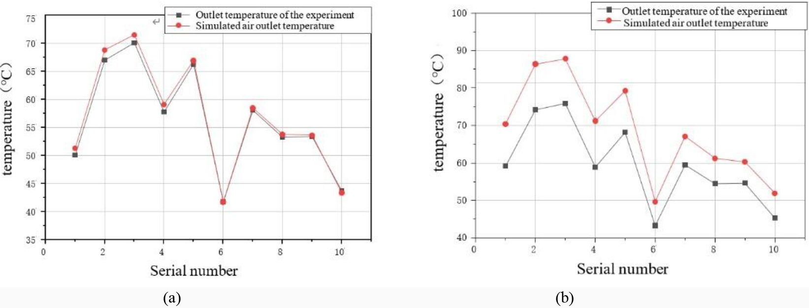
Under similar parameters of input air temperature, airflow, inlet water temperature, and flow rate, as illustrated in Fig. 5, the simulated outlet air temperature is substantially higher than the actual outlet air temperature. A comparison of the two temperatures reveals an absolute error ranging from a minimum of 6.35
This chapter employs the established heating exchanger model to conduct numerical simulations under varying operational conditions, analyzing the heat exchange patterns between rows of finned tubes. Moreover, by arranging the finned tubes at different fin heights, we will establish optimization models for three types of heating exchangers and conduct an optimization study.
Simulation study of heating exchanger
In this subsection, we examine the heating exchanger model outlined in Chapter 4, maintaining a constant flow rate and inlet temperature for the secondary medium, while altering the wind speed and temperature at the inlet of the finned tube array facing the wind. In this scenario, the secondary water flow rate in the heating exchanger is 0.65 m/s, with an inlet water temperature of 40
Temperature change and analysis of heating exchanger medium
Graphs were drawn to demonstrate the relationship between changes in the water side heat absorption of the heating exchanger under different inlet wind speeds and temperatures, as shown in Fig. 5-1.
Variation of heat absorption of the cold fluid in a heating exchanger.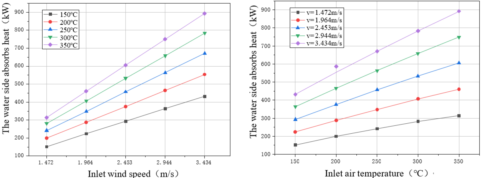
As depicted in Fig. 6, the left graph represents the change in water side heat absorption of the heating exchanger at different inlet wind temperatures as the inlet wind speed increases. As the inlet wind temperature increases gradually, the slope of the heat absorption growth curve also escalates. The right graph shows the change in water side heat absorption of the heating exchanger at different inlet wind speeds as the inlet wind temperature increases. As the inlet wind speed increases, the slope of the heat absorption curve also gradually ascends. It is evident from the graph that with equal increments of inlet wind temperature and wind speed, the growth rate of heat absorption on the water side of the heating exchanger progressively increases. In terms of heating exchanger operation, higher temperature and velocity of inlet supply air are more conducive to enhancing the heat exchange performance of the heating exchanger [11].
To further comprehend the heat exchange capability of the tube array in the heating exchanger along the direction of air flow, we can calculate the proportion of the temperature rise in each column of heat pipes to the total temperature rise on the secondary side, as depicted in Fig. 5-2.
When the temperature of inlet air is 150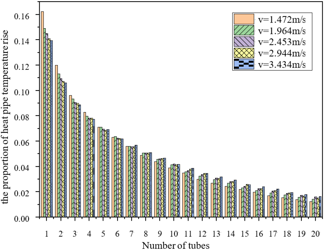
From the analysis of Fig. 7, with the temperature of inlet air of the heating exchanger at 150
By calculating the temperature rise proportion of a group of 5 heat pipes, we find that when the inlet wind speed is 1.472 m/s, the temperature rise proportion of the first group of heat pipes is 0.532, exceeding 50% of the total temperature rise, the second group’s proportion is 0.251, the third group’s is 0.138, and the fourth group’s is 0.079. When the inlet wind speed is 3.434 m/s, the sum of the temperature rise proportions of four groups of 5 heat pipes is 0.481, 0.259, 0.16, and 0.1, respectively. It can be seen that the temperature rise proportion of the first two groups of 5 heat pipes in the heating exchanger is too high, accounting for about 75% of the total temperature rise, while the temperature rise proportion of the last two groups of 5 heat pipes is relatively small. The proportion of temperature rise of the front row of heat pipes in the direction of the heating exchanger facing the wind is too high, which means the thermal power of the finned tubes is too great, while the efficiency of the rear heat pipes is very low, which is very detrimental to the continuous safe use of the heating exchanger and is economically inefficient.
Upon analysis of the simulation data at different wind temperatures, the variation rule of the temperature rise proportion of the heat pipes in the heating exchanger under varying temperature of inlet airs is the same as that in Fig. 7. As the inlet wind speed increases, the temperature rise of the single-column heat pipe becomes more uniform in relation to the total temperature rise, but the degree of uniformity improvement is limited. When the inlet wind speed of the heating exchanger is fixed, as the temperature of inlet air rises, there is no significant change in the temperature rise proportion of the single-column heat pipe, which can be ignored.
To sum up, during the operation of an Electric Heating Solid Energy Storage Heating System, the heat exchange capability of hot air remains finite, regardless of the magnitude of the temperature or velocity of the air entering the primary side of the heating exchanger. When designing the heating exchanger, an approach that initially determines the windward area of the heating exchanger and subsequently increases the amount of heat pipes in the direction of hot air flow to enlarge the heat exchange area, ostensibly to enhance thermal power, is impractical. Such a design strategy could lead to a wasteful utilization of tubes, and only offers limited improvement to the heat power of the heating exchanger [12]. For the finned tube heating exchanger under study in this research, it is recommended to maintain the amount of tube rows in the direction of air flow within a range of 10 to 15. The expansion of the heat exchange area could be achieved by considering an increase in the length of the tube rows on the windward side of the heating exchanger and the amount of vertically arranged tube rows.
The temperature variation of the secondary side fluid reflects a changing trend in the heat exchange capability of the finned tube, and the non-uniformity coefficient quantifies this trend. In the context of the Electric Heating System with Solid Energy Storage, excessive outlet air temperature from the energy storage body and extensive temperature changes in the heat pipe medium pose a serious threat to the safe use of the finned tube, especially the fins. Consequently, we introduce a coefficient of temperature drop uniformity for the shell side air, establishing a function relationship between air-side temperature variation and tube row quantity. This measure illuminates the proportion of temperature drop as high-temperature air from the primary side of the heating exchanger sweeps across each column of tube bundles compared to the average temperature drop from heat pipes sweeping across a row of tube bundles. This discrepancy, to some extent, can indicate the rationality of the heating exchanger structure. From calculations, it can be deduced that the non-uniformity coefficient of the air-side temperature of the heating exchanger drop changes with variations in temperature of inlet air and velocity, as shown in Fig. 5-3.
Unevenness coefficient of temperature decline at the air-side of the heating exchanger.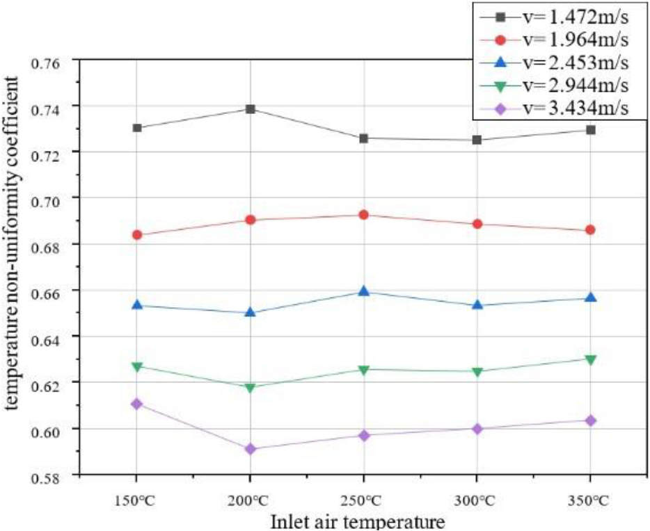
According to Fig. 8, the non-uniformity coefficient of the heating exchanger’s air-side temperature decrease is mostly impacted by the heating exchanger’s intake air speed. An increase in input air speed leads in a reduction in the non-uniformity coefficient for a given temperature of inlet air, hence improving the uniformity of the air-side temperature drop in the heating exchanger. This increase also reduces the magnitude of temperature change as high-temperature air sweeps across each column of tube bundles, thus improving the safety performance of the heating exchanger. When the temperature of inlet air of the heating exchanger is 200
As discussed in previous sections, changing the operating parameters of the heating exchanger has an effect on heat exchange performance. However, the impact is somewhat constrained and may result in considerable waste of energy and resources. Regarding the current heating exchanger structure, the significant temperature variations in the initial few rows of heat pipes are detrimental to the secure operation of the heating exchanger, necessitating a structural optimization study [13].
In accordance with the simulated study of the heating exchanger in Subsection 5.1, it was observed that for the 20 rows of finned tube bundles along the direction of air flow on the shell side of the heating exchanger, the temperature rise in the first 10 rows of heat pipes accounted for approximately 75% of the total temperature rise. To ensure the heating exchanger optimization study does not adversely affect its heat exchange capacity, the structural optimization in this chapter arranges for the first 10 rows to comprise finned tubes of varying heights. The arrangement is such that shorter finned tubes precede taller ones, with the latter 10 rows consisting of 14 mm fins [14] (consistent with the finned tube type in Chapter 5). The specific combination of heating exchanger finned tubes is detailed in the following table.
Describes the optimal structural combination modes
Describes the optimal structural combination modes
The heat exchange models of the heating exchangers with the above varied structures were established. The boundary conditions for numerical simulation of these heating exchangers were set as follows: the secondary side water velocity was 0.65 m/s, the intake water temperature was 40∘C, the temperature of inlet air was 350∘C, and the inlet air speed was set to 1.472, 2.453, and 3.434 m/s, respectively.
Outlet temperature of medium under different structure of heating exchanger.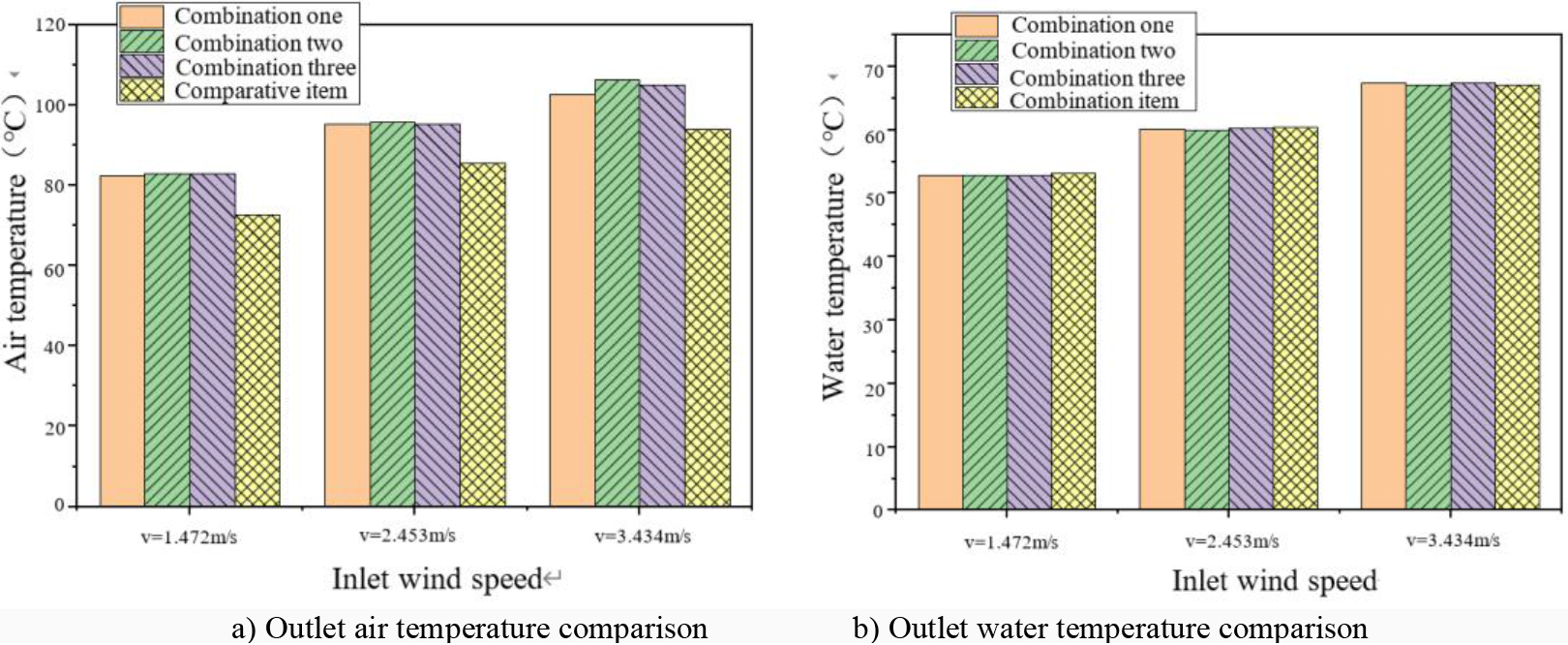
Figure 9a presents a comparative analysis of the outlet air temperatures under different heating exchanger structures. At an inlet air speed of 1.472 m/s for the heating exchanger, the outlet air temperatures of Combination One, Two, and Three are remarkably close and distinctly higher than that of the comparison item. This suggests that from an energy consumption perspective, the combination-structured heating exchangers consume less heat on the air-side. As the inlet air speed to the heating exchanger increases, the temperature difference in the outlet air among the three combination structures gradually widens. Generally, Combination One exhibits the lowest outlet air temperature, followed by Combination Three, with Combination Two having the highest. Figure 9b provides a comparative analysis of outlet water temperatures under different heating exchanger structures. At an inlet air speed of 1.472 m/s for the heating exchanger, the outlet water temperatures of the three combinations are closely aligned and slightly lower than the comparison item. As the inlet air speed to the heating exchanger increases, the outlet water temperature escalates, and the temperature difference between the outlet water of the three combination structures and the comparison item gradually diminishes. When the heating exchanger inlet air speed is 3.434 m/s, the outlet water temperatures of Combination One and Three are higher than the comparison item, while the temperature difference between Combination Two and the comparison item is a mere 0.01
The objective of this subsection is to propose an appropriate heating exchanger structure that enhances the safety performance of the heating exchanger, while ensuring its heat exchange capability, thereby aiming to conserve energy and reduce costs. Consequently, the optimization of the heating exchanger’s performance primarily considers the impact of shell-side heat exchange on the heat tubes, including the proportion of air-side temperature drop in different heating exchanger structures.
Ratio of wind temperature drop under different structure of heating exchanger.
Analyzing Fig. 10, which presents the proportional air-side temperature drop in different heating exchanger structures, We discover that the distribution of the air-side temperature decrease corresponds to the configuration of the fin heights in the heating exchanger tube rows. Along the direction of high-temperature airflow, increasing the fin height of the heat tubes can, to some extent, enhance the proportion of the temperature drop as high-temperature air sweeps across the heat tubes. An ordered distribution of different fin heights can reduce the maximum value of the air-side temperature drop and increase the minimum value, which promotes more uniform heat exchange in the heating exchanger tubes. As previous chapters’ studies have shown, increasing the air speed at the heating exchanger inlet results in a more uniform proportion of the temperature rise per heat tube relative to the total temperature rise. This rule also applies to the air-side temperature drop [15].
In Fig. 10, the maximum and minimum air-side temperature drops per heat tube for Combination One are 0.1216 and 0.0122, respectively. For Combination Two, the corresponding figures are 0.0997 and 0.0123, and for Combination Three, they are 0.0852 and 0.0121. Of the three combinations, Combination Three has the smallest maximum air-side temperature drop, indicating that Combination Three plays the most significant role in reducing the temperature drop per heat tube in the heating exchanger. The minimum air-side temperature drops for all three combinations are in the twentieth row of heat tubes, with very small numerical differences, suggesting that the last ten rows of finned tubes in the heating exchanger have fulfilled their heat exchange purpose. The trend of the air-side temperature drop, as shown in Fig. 10, also reveals that the increase in the values of the first ten heat tubes in Combination Three is more gradual and stable compared to the other two combinations.
The temperature non-uniformity coefficient of the air-side temperature drop in the heating exchanger can be calculated using the data obtained from the simulation calculations of the three combination heating exchangers, as shown in Fig. 4-6.
Unevenness coefficient of wind side temperature drop under different structures of heating exchanger.
Figure 11 reveals a significant reduction in the temperature non-uniformity coefficient for the air-side temperature drop in all three combination structures compared to the control group, following a change in the airspeed at the heating exchanger inlet. In the control group, the coefficients of temperature non-uniformity were calculated at inlet air speeds of 1.472 m/s, 2.453 m/s, and 3.434 m/s are 0.7294, 0.6565, and 0.6036, respectively. For Combination One, the coefficients are 0.4324, 0.4081, and 0.375; for Combination Two, they are 0.3847, 0.3339, and 0.2806; for Combination Three, they are 0.4269, 0.3599, and 0.3096. Upon calculation, the average temperature non-uniformity coefficients for Combinations One, Two, and Three are 0.4052, 0.3331, and 0.3655, respectively. Compared to the average temperature non-uniformity coefficient of the original heating exchanger model, the uniformity has improved by 38.9% for Combination One, 49.78% for Combination Two, and 44.89% for Combination Three.
The above data indicates that among the three optimized heating exchanger structures, Combination Two exhibits the most substantial improvement in the uniformity of the air-side temperature drop, followed by Combination Three, with Combination One performing the least effectively.
This research addresses prevalent issues in the application of heating exchangers within Electric Heating Solid Energy Storage Heating Systems, including suboptimal compatibility of the heating exchanger and the energy storage unit, poor safety performance, and overall inefficiency in heat exchange. The finned tube heating exchanger, applicable in practical engineering, served as the study object. A combination of experimental testing and numerical simulation was used for investigation, leading to the following conclusions:
In the heat exchange performance tests, the principal factor affecting the heat exchange efficiency of the heating exchanger was the volume of air flow. The heat exchange efficiency in this experiment was mostly between 60%–80%, generally on the lower side. The close similarity of the return air temperature to the secondary side supply water temperature can be attributed to an excessive amount of finned tube rows in the heating exchanger, resulting in minimal heat exchange in the latter half of the tube shell. This indicates an irrational structure of the heating exchanger tube array. The variation in heat transfer inside the heating exchanger is greatly impacted by the velocity and temperature of the incoming air in the numerical simulation study of the heating exchanger. Higher input air temperature and velocity are more favourable to boosting the heating exchanger’s heat exchange efficiency. In terms of temperature variance in single-row heat pipes, the first two sets of five columns in the heating exchanger account for roughly 75% of the overall temperature increase. The large percentage of temperature increase in the front row of heat pipes is detrimental to the continued safe operation of the heating exchanger, and it also creates economic inefficiencies. To a limited extent, increasing the velocity of the air entering the heating exchanger may improve the temperature uniformity of single-row heat pipes. During the design process of the heating exchanger, in order to enhance the thermal power of the heating exchanger, it is irrational to initially determine the windward area of the heating exchanger and then increase the amount of heat pipes in the direction of hot air flow, thereby enlarging the heat exchange area. This design method could likely lead to the wastage of pipe material and a limited elevation in the thermal power of the heating exchanger. For the same type of finned tube rows studied in this topic, it is recommended that along the direction of air flow, the amount of tube rows should be maintained within 10 to 15. The increase in the heat exchange area can be considered by increasing the length of the tube rows on the windward side of the heating exchanger as well as the amount of vertically arranged tube rows. Taking into account the optimization effects of the combined structure heating exchanger medium temperature variation, the air-side temperature drop ratio change, and the temperature non-uniformity coefficient, the heating exchanger with finned tube combinations of 4 mm double rows, 6 mm double rows, 8 mm double rows, 10 mm double rows, 12 mm double rows, and 14 mm ten rows, arranged from front to back, demonstrates the best overall optimization effect. When the air speed at the heating exchanger inlet is high, the heat exchange capability of this combination surpasses the original structure, and the uniformity of the air-side temperature drop in this structure has improved by 44.89%, while saving 25.62% of finned surface area.
Footnotes
Acknowledgments
A grant for this work was provided by the Hebei innovation capability improvement project (1924 4503D).