
Abstract
Pressure and flow rate are the most important hydraulic parameters in natural gas pipeline flow, and leak rate is the most crucial parameter after a leak accident occurs. The study of these parameters is vital to the safey of natural gas pipelines and risk assessment after accidents. In this research, based on the conservation laws universally applicable to the motion of objects, we establish the fundamental control equation group for natural gas flow. Then, for both normal and leak conditions of pipelines, we use the characteristic line method to derive the corresponding difference equations for the fundamental control equations, thereby providing calculation methods for pressure and flow rate. Finally, we investigate the calculation method of natural gas pipeline leak rate under different leak aperture sizes, and validate the accuracy of this method through simulation examples.
Keywords
Introduction
In today’s rapidly developing world, with a high demand for energy and alarming levels of greenhouse gas emissions leading to severe environmental pollution, economic sustainability and human survival face enormous threats. The severity of this situation has led countries worldwide to place great emphasis on energy conservation and environmental protection. Natural gas, as a new energy source of the 21st century, has many advantages such as high calorific value, low environmental pollution, abundant reserves, and high economic benefits. It plays an vital role in improving the energy structure, alleviating energy supply-demand conflicts, and enhancing environmental quality. Natural gas has already become the third-largest energy source following coal and oil, and is hailed as the environmentally friendly energy source of the 21st century. Natural gas pipeline transportation is a complex and sophisticated system. The safety of this system lies on several factors, which including the design and construction of the pipelines, the quality of the materials used, the monitoring and maintenance of the pipelines, and the training and competence of the personnel involved. In recent years, there have been several incidents of natural gas pipeline leaks and explosions that have caused significant damage and loss of life. These incidents have highlighted the importance of safety in natural gas pipeline transportation and the need for rigorous safety measures to prevent and mitigate pipeline failures.
After a pipeline leakage accident, the importance of pipeline leakage for safety should not be ignored. The leaked natural gas can cause a range of problems, including fire, explosion, and environmental pollution, among others. Therefore, it is critical to have effective detection and mitigation systems in place to address pipeline leaks promptly. The importance of natural gas pipeline leakage for safety also extends to the response and recovery efforts after a leakage incident. The response should be swift, coordinated, and efficien. Therefore, studying the natural gas flow in pipelines under normal and leak conditions is of important practical significance for accident prevention and emergency response.
Through the literature search, we have identified several scholars who have made significant contributions to the study of hydraulic parameters and natural gas pipeline flow as well as the detection and estimation of pipeline leak rates. For instance, in their work, Smith et al. (2014) invested a hydraulic model for predicting the flow behavior of natural gas in pipelines [1], while Jones et al. (2017) focused on investigating advanced sensing technologies for pipeline leak detection and prevention [2]. Other notable researchers in this field include Brown et al. (2015), who developed several research on the impact of flow rate and viscosity on hydraulic parameters in natural gas pipeline flow [3], and Wang et al. (2018), who proposed a novel method for optimizing pipeline performance using the method of characteristic line [4]. Chen et al. (2015) put forward a method for leak detection of gas pipeline employing the method of characteristic line [5]. Similarly, Liu et al. (2016) utilized the method of characteristic line to calculate the leakage rate [6]. In their study, Li et al. (2018) proposed a method for detecting gas pipeline leaks by combining the wavelet transform and the method of characteristic line [7]. Zhou et al. (2019) suggested a technique for calculating the leakage rate using the method of characteristic line and machine learning approaches [8]. Furthermore, Yin et al. (2020) introduced a transient temperature and pressure variations based leak detection method, employing the method of characteristic line in conjunction with artificial neural networks [9]. Lastly, Wang et al. (2021) presented a leak detection method which based on spectral analysis of temperature and pressure variations using the method of characteristic line [10] Montiel et al. [11] initially presented the hole-pipe model and the application of various models for detecting leakage. Zhou et al. [12] performed an analysis of the gradual discharge of gas storage tanks, focusing on the thermal process, and developed a corresponding mathematical model. Levenspiel [13] formulated a leakage model specifically tailored for complete pipeline fractures. Their investigation involved analyzing the pressure descend along the pipeline, assuming constant pressure at the beginning point and adiabatic natural gas flow and leak processes within the pipe. Additionally, Dong et al. [14] calculated the steady gas leak rate in pipelines. Furthermore, several researchers have explored pipeline health monitoring and leak detection [15, 16, 17, 18, 19, 20, 21].
The above research reveals that the majority of studies on natural gas pipeline leak rate calculations are based on the research findings proposed by Montiel et al. [11], lacking new perspectives and innovations.
Fundamental control equations for natural gas flow
The dominating equations of control for the flow of natural gas encompass the continuity equation, momentum equation, energy equation, and the gas state equation when dealing with gases. These fundamental control equations are applicable to both normal and leakage conditions in natural gas pipelines. To establish the basic control equations for natural gas flow in pipelines, certain reasonable simplifications can be employed, based on the following three assumptions [11]:
One-dimensional gas flow within the pipeline; The pipeline is rigid; The slope of a specific section of the natural gas pipeline remains constant.
Under these above assumptions, the following set of basic control equations can be derived:
(1) Continuity equation
where
(2) Momentum equation
where
(3) Energy equation
where
(4) Gas state equation
where
The flow state in a pipe can be divided into two categories: transient flow and steady-state flow. Transient flow refers to the flow parameters at any point along the pipeline not only being dependent on the location but also on time. Therefore, the above basic control equations for natural gas flow (Eqs (1) to (4)) can also be referred to as the transient flow equations for natural gas pipelines. Steady-state flow, on the other hand, refers to the flow parameters at any point along the pipeline being dependent only on the location and not on time. When it is steady-state flow, the partial derivative terms with respect to time in Eqs (1) to (4) are zero.
Pressure and flow rate are the most crucial hydraulic parameters in natural gas pipelines. Researching their calculation methods holds significant importance in ensuring pipeline safety and enabling gas leak detection in natural gas pipelines. Equations (1) to (4) accurately represent the transient flow of natural gas pipelines, but for practical engineering applications, further simplifications can be made. In the case of long, straight pipelines, the difference of temperature between the surrounding soil and pipe’s outer wall, heat between the wall and the gas in the pipe should be considered small. As a result, we can assume that the flow within the pipeline is isothermal, then calculations made under this assumption yield acceptable results. Consequently, when temperature variations inside the pipeline are not taken into account, the energy Eq. (3) can be disregarded. Moreover, the gas flow velocity and sound speed within the pipeline are much smaller compared to the fluid velocity. Hence, the convective part in Eq. (2) can be ingored. Additionally, if the discrepancy in elevation is small, the gravity part can be ignored as well. Furthermore, the Eqs (1) and (2) are derived based on the study of fluid with unit volume. For practical convenience, the mass flow rate is introduced by utilizing the control equation for fluid with unit mass. Therefore, the following simplified equations can be obtained:
where
Equations (5) and (6) represent hyperbolic partial differential equations that are challenging to get an analytical solution. The method of characteristics is a numerical calculation technique based on the theory of characteristics, used to solve systems of hyperbolic partial differential equations. This method is highly mature and capable of providing highly accurate numerical solutions. With the advent of electronic computers, the method has become more refined and widely applied.Therefore, this method is employed to solve these equations in this paper, the basic concept behind applying the characteristics line method to derive the partial differential Eqs (5) and (6) involves several steps. Firstly, the equations are deformed into normal differential equations by using the characteristic lines. This deformation helps simplify the problem by reducing it to ordinary differential equations. Next, the ordinary differential equations is further transformed into a system of difference equations, allowing for discrete calculations at specific points along the characteristic lines. This discretization is a crucial step in the numerical solution process. Finally, mathematical methods are utilized to convert the system of difference equations into a system of nonlinear equations. These equations, along with the initial and boundary conditions, are then solved numerically using appropriate numerical algorithms. Overall, the method of characteristics provides a systematic approach to numerically solve hyperbolic partial differential equations like Eqs (5) and (6), offering a practical and effective solution method in engineering applications.
Equations (5) and (6) can be represented as
The two equations are linearly combined using an arbitrary unknown multiplier
We can select two values for
If we compare the first term of Eq. (8) with Eq. (9), and the second term within the parentheses of Eq. (8) with Eq. (10), and satisfy the following conditions:
Therefore, Eq. (8) can be transformed into an ordinary differential equation:
Equation (11) is equal to Eq. (12), that is:
Solving the above equations, we obtain that
Equation (15) is the two conditions that Eq. (13) must satisfy.
By substituting the values of
The characteristic equations
Pipeline characteristic lines under normal condition.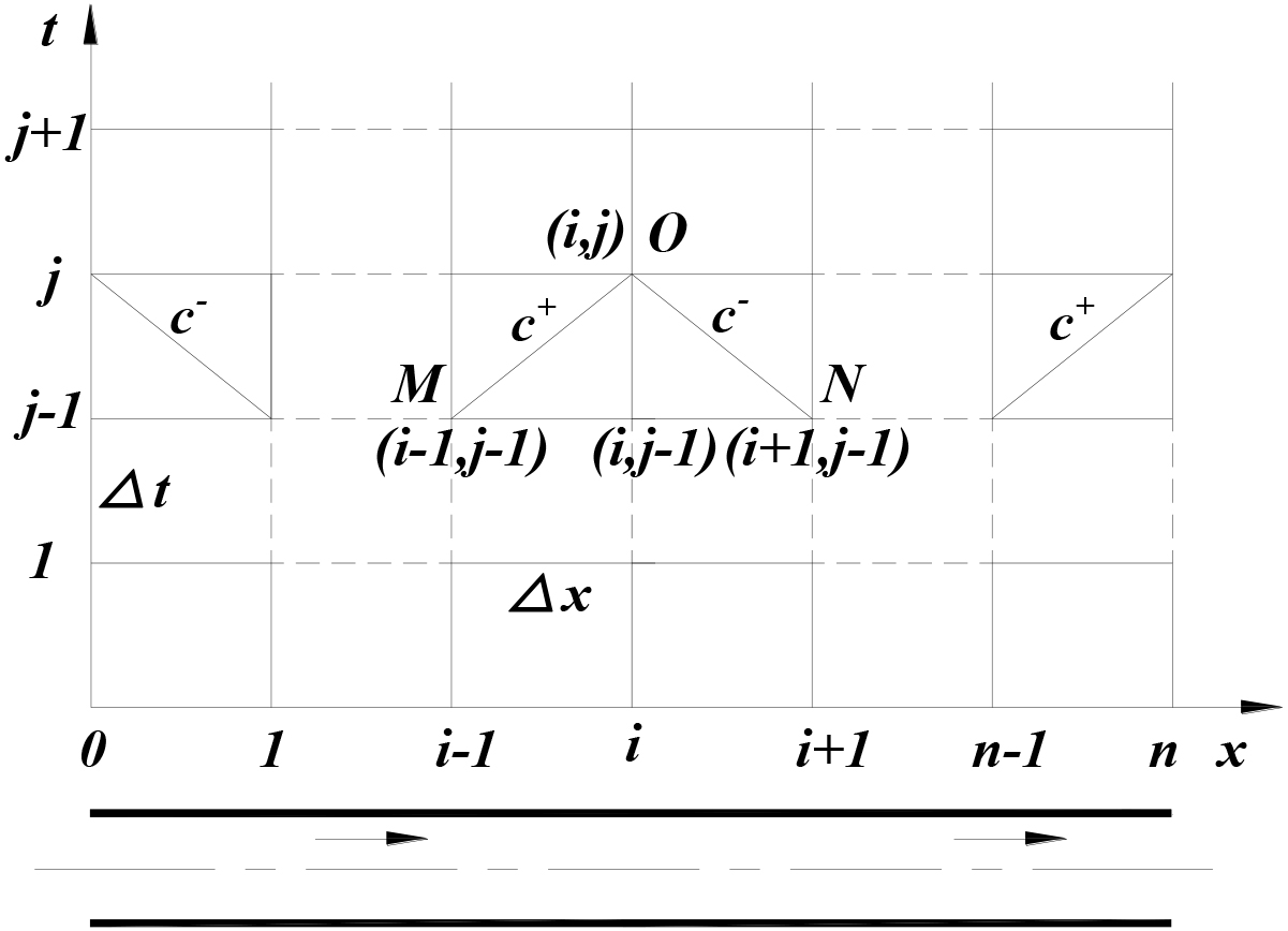
Equations (3) and (3) represent two equations that satisfy the
In Fig. 1, there exists only one characteristic equation at each ending of the pipeline, which implies that the flow rate and pressure at the endpoints cannot be directly determined. Hence, it is essential to provide boundary conditions related to these two parameters at two ends of the pipe to obtain these two parameters at each time on the boundary. These boundary conditions play a crucial role in solving the differential equations accurately and comprehensively.
Similar to the calculation method under normal conditions, when considering a sudden leak occurring at a specific point on the pipeline, we can still utilize the characteristics line method to solve the simplified Eqs (5) and (6). As depicted in Fig. 2, let’s assume that one sudden leak occur at node
Pipeline characteristic lines under leakage condition.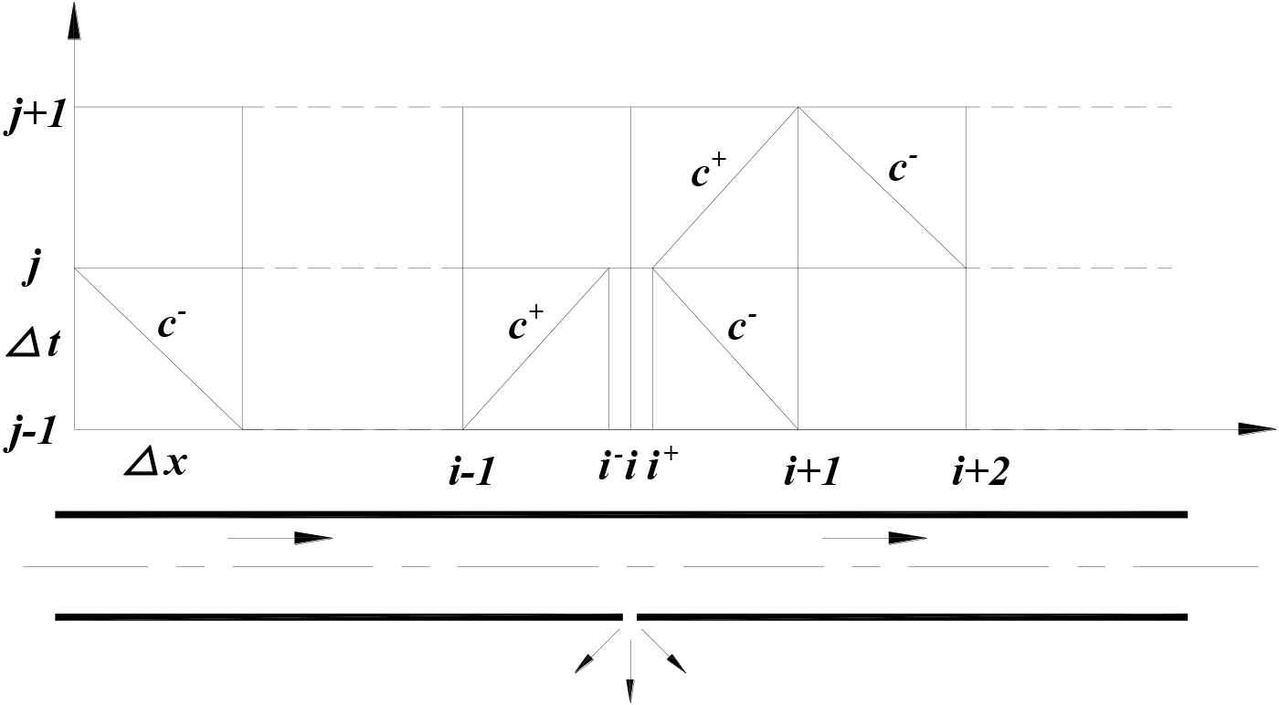
By introducing first-order approximation, we can obtain the difference equations for node
where,
Equations (4) and (4) represent two equations satisfied at time
In general, assuming that the momentum variation in the horizontal direction caused by the leak can be neglected, the pressure before and after the leak remains constant. Additionally, if the amount of the leak is confirmed, the flow rate relationship after and before the leak can be established based on the mass conservation principle. Under these assumptions, these boundary conditions can be specified as follows:
By incorporating the boundary conditions Eqs (22) and (23) at the leak point into the difference Eqs (4) and (4), we obtain a four equations system with four unknowns. This system allows us to calculate the flow rate and pressure after and before the leak point at any given time.
At the endpoints of the pipeline, similar to the normal condition case, we only need to provide boundary conditions regarding the flow rate and pressure. This enables us to determine the flow rate and pressure at various points along the boundary at each time interval. The calculation method for the flow rate and pressure at each node outside of the leak point and pipe endpoints follows the same approach as the calculation method under normal conditions.
By applying these calculations and considering the appropriate boundary conditions, we can determine the flow rate and pressure at various points along the pipe, including leak point, as the transient flow progresses.
The leak rate is time-dependent, with the maximum leak rate typically occurring at the moment the leakage starts. However, in practical engineering scenarios, it is often sufficient to determine the maximum leak rate, which corresponds to the leak rate under steady-state conditions. Therefore, this part zooms in on the calculation method for the maximum leak rate of a natural gas pipeline.
Figure 3 is a sketch map of natural gas pipeline leakage, assuming a leakage occurs at a distance
Sketch map of gas pipe leakage.
In general, natural gas pipeline leaks are considered as orifice leaks, and the leak process can be viewed as the outflow of compressible gas through an orifice. Different shapes of leak holes are converted to circular orifices for calculation. For ease of calculation, these assumptions are proposed: (a) the flow in the pipe is one-dimensional; (b) the flow is adiabatic in the pipe; (c) the flow is isentropic at the leak point; (d) the motion of the gas follows the laws of ideal gases. As the assumption is made, that the energy and momentum conservation equations are obtained [11]:
In the context of pipeline leaks, it is common to treat them as orifice leaks, where the leakage process is modeled as the outflow of compressible gas through an orifice. To simplify the calculation, various shapes of leak holes are approximated as circular orifices. So as to streamline the analysis, these assumptions are proposed:
One-dimensional flow: The flow is assumed to occur in a single dimension, simplifying the calculations in the pipe. Adiabatic flow: The flow in the pipeline is considered to be adiabatic, meaning there is no significant heat transfer between surroundings and the gas. Isentropic flow at the leak point: It is assumed that the flow is isentropic at the leak point, meaning there is no entropy change during the flow through the leak orifice. Ideal gas behavior: The gas is assumed to follow the laws of ideal gases, then the ideal gas equation can describe the relationship of pressure, volume, and temperature.
By assuming adiabatic flow in the pipeline, the conservation equations for energy and momentum can be applied to derive the equations necessary for the analysis [11]:
where
The hydraulic friction coefficient
When Re is large enough to reach fully turbulent flow, a and b become independent of each other.
For pipes with rough inner walls:
For pipes with smooth inner walls:
By substituting Eqs (1) and (4) into Eq. (24), the expression for the leak rate
where
The nature of the gas flow at the leak point, whether it is supersonic or subsonic, has a great influence on the calculation of leak rate. Considering that the atmospheric pressure outside the pipeline is known, this article assumes the critical pressure value (CPR) to be:
When
When
When the leakage occurs, the parameter values at points 1 and 4, the atmospheric environment, then the mass flow rate before leak point are known, while the parameter values at points 2 is unknown. After observing Eqs (26) or (28), it can be found that the parameters at point 2 are the key parameters for calculating the leak rate. Therefore, the following research focuses on how to calculate the parameters at point 2.
There are three main differences between natural gas pipeline leaks and classical orifice flow, which are also the key factors to accurately calculate the leak rate These three key factors are:
Frictional pressure drop. Frictional flow of natural gas from point 1 to point 2 causes a pressure drop from The occurrence of a leakage in the natural gas pipeline will result in a reduction in pressure at the leak point ( The presence of a leak affects the upstream flow rate of leak point. The upstream flow rate is equal to downstream flow rate plus leak rate. Therefore, the occurrence of a leak disrupts the normal flow pattern, causing a change in the upstream flow rate of leak point. This change in upstream flow rate, in turn, influences the pressure in the pipe. The altered pressure conditions can impact the leak rate, leading to a further modification in the upstream flow rate. This interplay between pressure, flow rate, and leakage forms a feedback loop, where changes in one parameter affect the others.
Key factor c) is not considered in Montiel’s proposed leak rate calculation method [11], making it an innovative aspect of this study.
The Basic model, which ignores factors a), b), and c), assumes constant parameters at points 1 and 2 before and after the leak. It utilizes Eqs (26) or (28) to calculate the leak rate. While the Basic model is suitable for calculating the flow rate of high-capacity container orifice flow, it is not well-suited for calculating the leak rate. This is because the Basic model overlooks several important factors. Firstly, Once a leak occurs, the total pressure inside the pipeline decreases, particularly at point
Improved model
By neglecting factors b) and c) while considering factor a), the resulting leak rate calculation model is known as the Improved model. This model consider the pressure drop caused by frictional flow from point 1 to point 2, thereby improving the accuracy compared to the Basic model for calculating leak rates. However, as factors b) and c) are disregarded, the leak rate determined by this model will still be higher than the actual leak rate, albeit lower than the leak rate which calculated by this model. Consequently, Improved model is suitable for preliminary leak rate calculations involving small leakage apertures.
Assuming a constant coefficient of friction along the entire pipe, the parameter relationship between point 1 and 2 is as follows:
where
In the above equations, Ma is the Mach number, that:
By using Eqs (29)–(34), the parameters at point 2 can be calculated, and then Eqs (26) or (28) can be employed to calculate the leak rate.
Under these conditions, these relationships can geted:
When
When
If all three factors a), b), c) are considered, then the resulting model is a Final universal model. For the sake of computational convenience, we assume that the pressure
Using Improved model, we calculate the leak rate If If
Figure 4 shows the flowchart for the Final universal model,
Flow sheet of the Final universal model.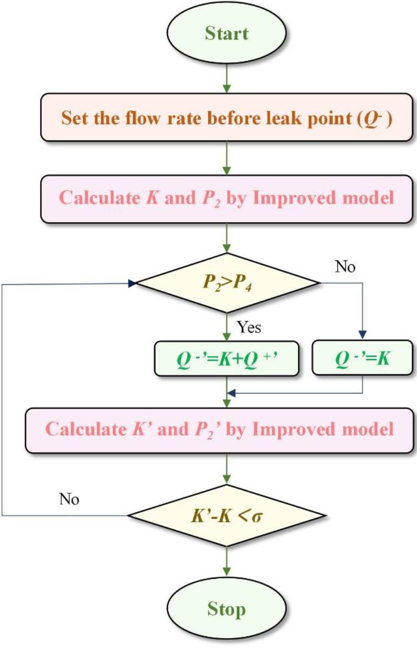
During these outlined steps, it becomes evident that
(a). Subcritical flow in the pipe, critical flow at leak point.
In this case, Eq. (28) is used in step 1 to calculate the leak rate using Improved model.
(b). Subcritical flow in the pipe, subcritical flow at leak point.
In this case, Eq. (26) is used in step 1 to calculate the leak rate using Improved model.
(c) Critical flow in the pipeline, critical flow at leak point.
In this case, Eq. (28) is used in step 1 to calculate the leak rate using Improved model.
Equation (28) is applied in step 1 to calculate the leak rate using the Improved model. Additionally, as previously mentioned, the pressure
It is dangerous to conduct an experiment for leak rate measurement on actual natural gas pipelines. Even when using compressed air instead, it is difficult to simulate multiple leaks with different aperture sizes to cover a range of
Simulation parameters
Simulation parameters
Figure 5 depicts the correlation between the leak rate and
Correlation between leak rate 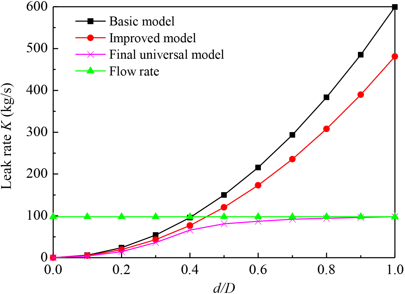
When dealing with very small leak holes, the Improved model is recommended. The diagram illustrates that the leak rate of natural gas calculated using the Basic model is greater than the Improved model, which aligns with the internal friction effect of the latter. As a result, the Improved model is more precise in predicting natural gas leak rates compared to the Basic model. Leakage causes a reduction in pressure at point 2, although not indefinitely, leading to a smaller leak rate calculated by the Final universal model than the Improved model. Nonetheless, the difference is insignificant. Therefore, the leak rates predicted by both models are similar when the aperture is small. However, as the aperture expands, the impact of the pressure reduction on the leak rate at point 2 becomes more pronounced. Consequently, the leak rate will plateau, becoming stable and smooth, eventually matching the flow rate (When the value of
In practical leak scenarios, the flow velocity before leak point tends to increase due to the leak. This increase in velocity leads to a decrease in flow pressure, following Bernoulli’s equation. However, the Improved model does not account for this effect, leading to an overestimation of the leak rate. In cases where the
Correlation between leak rate 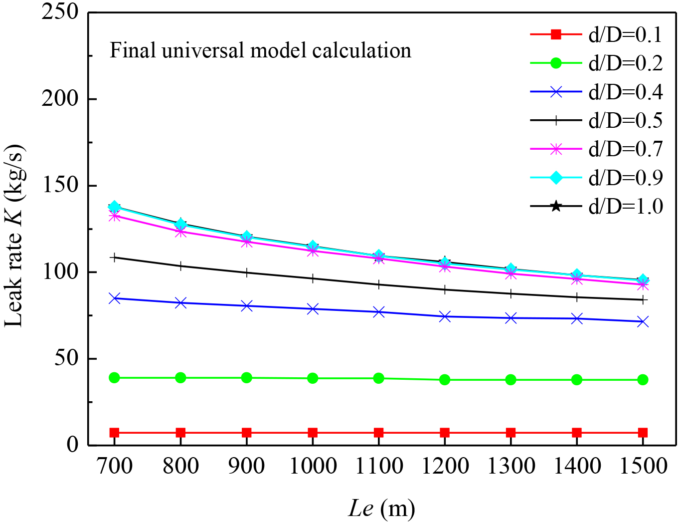
Figure 6 presents the correlation between the leak rate,
Correlation between leak rate 
Figure 7 displays the correlation between
This article focuses on the hydraulic parameters of natural gas pipelines, specifically pressure and flow rate, which are the most crucial factors based on the fundamental control equations governing the flow. The article then derives the differential equations corresponding to the basic control equations, using the method of characteristics, to obtain the calculation method of transient pressure and flow rate under normal and leak conditions of natural gas pipelines. Additionally, the article studies the calculation method of the leak rate, which takes into account the pressure drop caused by pipeline friction and uses a successive approximation mathematical method to consider the effect of leakage on leak point pressure and upstream flow rate. Through simulation examples, it has been demonstrated that this method is a universal and highly accurate method that can calculate leak rates for any pipe diameter.
Footnotes
Acknowledgments
The authors acknowledge the Scientific Research Project of Chengdu Vocational & Technical College of Industry (Grant: 20233050002), the Major Joint Research Project of Chengdu Vocational & Technical College of Industry (Grant: XJTD-2023-2) and the Master Studio of Chengdu Vocational & Technical College of Industry (Grant: XJDS-2022-1).