



Abstract
To address the concerns regarding a disused tailings pond, a closure engineering design and dam flood control safety evaluation were conducted. The proposed reservoir closure treatment methods, including adding flood drainage system (spillway), plugging the existing overflow tower and drainage pipe, were developed in combination with the construction conditions of the reservoir area. Then, hydrological calculations and flood routing for the tailings pond were performed, and the flood control safety of the tailings pond was evaluated. The results of the study indicate that after the designed closed pond treatment method for the tailings pond is adopted, a 1000-year design flood would result in a flood elevation of 0.7 m, a minimum safety super-elevation of 2.0 m, and a minimum dry beach of approximately 130 m. These findings are in compliance with the relevant regulations and requirements of the specifications, and thus ensure the flood control safety of the tailings pond.
Keywords
Introduction
In the field of metal or non-metal mining, tailings ponds serve as repositories for industrial waste and tailings generated after the separation of ores [1, 2, 3]. If a tailings pond has reached its designed final accumulation elevation and cannot be further expanded, or if there are safety issues during the construction process, closure treatment projects should be implemented [4, 5, 6, 7]. Closure design of tailings ponds plays a vital role in ensuring the stability and safety of tailings dams and protecting the surrounding environment of the reservoir area. Several researchers have explored the treatment method of closed reservoirs [8, 9, 10, 11]. For instance, Dragan Komljenovic suggested a comprehensive resilience-based method to analyze this phase of their life cycle, The proposed approach was tested through a case study conducted at an actual surface iron ore mine in Bosnia and Herzegovina [12]. Zuoan Wei conducted comprehensive geotechnical investigations of a tailings dam in China and presented a successful case study on heightening an existing tailings dam and extending its operational lifetime through the use of a new drainage technique termed the upward bending drain pipes system [13]. M. Rico compiled available information on historic tailings dam failures to establish simple correlations between the geometric parameters of tailings ponds (e.g., dam height, tailings volume) and the hydraulic characteristics of floods resulting from released tailings [14].
This study proposes a closed pond treatment method for a tailings pond project that has reached the design elevation and is no longer in use. The method involves adding a flood discharge system (spillway) based on site implementation conditions, demonstrating the rationality of the spillway design through flood routing analysis, and ensuring the flood control safety of the tailings pond after closure [15].
Overview of tailings pond engineering
The studied tailings pond was constructed in 1993, and put into operation in 1994 The mining enterprises were shut down and tailings ponds were also discontinued in 2008 According to the surveying and mapping map, site survey, and geotechnical engineering investigation report, the current top elevation of the tailings pond dam is 336.3 m, which is 3.7 m lower than the final phase’s original design elevation of 340 m, resulting in a current dam height of 86.3 m and a total storage capacity of approximately 4.62 million m3, classifying it as a third-grade tailings pond.
Notably, no safety or environmental protection incidents have arisen during the tailings pond’s production, and the operational status of the various safety facilities is generally satisfactory, rendering it a standard reservoir. The operational status quo of the tailings pond is as follows:
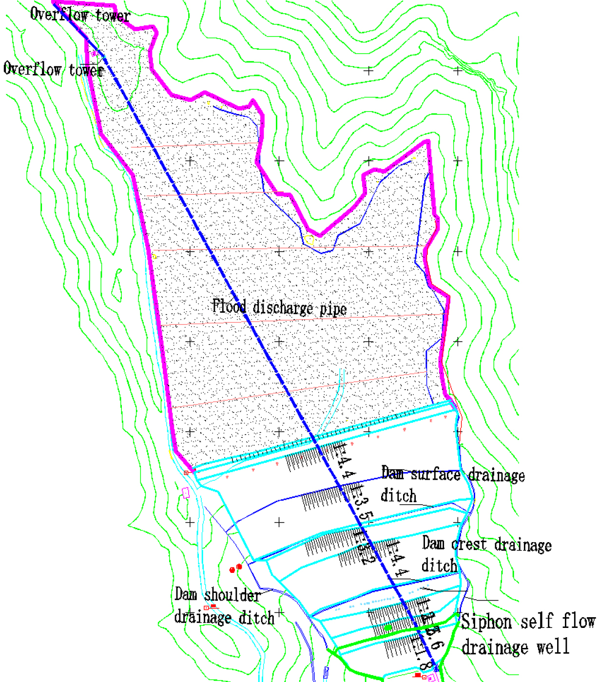
Initial dam. At the moment, the initial dam is classified as a permeable rockfill dam. The top elevation of the dam is measured at 277 m, with a corresponding top width of 3.5 m. Its initial height reaches 27 m, while the length of the dam crest stands at 135 m. The external slope ratio is noted to be at 1:1.8. Tailings stacking dam. The tailings stacking dam was constructed utilizing the upstream method of coarse tailings. Presently, the top elevation of the dam stands at 336.3 m, while its total height measures 59.3 m. The slope structure of the stacking dam is complete, and there is no occurrence of either collapse or local slide phenomenon. Moreover, the beach surface is noted to be dry, with no presence of water. Drainage ditch. The abutment drainage ditch has been established at the intersection of the tailings accumulation dam body and the hillside of both banks during the later period. Currently, the existing length of the abutment drainage ditch spans approximately 480 m. Additionally, a crest drainage ditch with a length of 179 m has been established at the top of the sub-dam parallel to the dam axis with an elevation of 289.1 m. Moreover, a crest drainage ditch with a length of 263 m has been constructed at the top of the sub-dam parallel to the dam axis with an elevation of 312.1 m. Lastly, a crest drainage ditch with a length of 278 m has been implemented at the bottom of the sub-dam parallel to the dam axis with an elevation of 323.5 m. The configuration of the crest drainage ditches can be visualized through Fig. 1.
Drainage ditch distribution of the dam body. Drainage facilities and infiltration lines. In late October 2005, siphon artesian drainage wells were incorporated into the tailings reservoir to effectively decrease the saturation line of the dam body. A horizontal drainage pipe has been embedded in the tailings reservoir at an elevation of 319.0 m, which significantly lowers the saturation line of the dam body during later stages. Currently, there is no water present in the reservoir, and the in-situ measured infiltration line is minimal. The siphon wells located on the east and west sides of the dam are at a depth of approximately 12 m, whereas those in the middle are approximately 15 m deep. The deepest siphon well in the middle measures at a depth of 20 m, which meets the required regulations. Drainage system. The tailings pond’s flood drainage system adopts a tower-pipe flood drainage system. A reinforced concrete overflow tower with a 2.0 m inner diameter is installed in the reservoir area. The window tower features eight water intakes in each row, with the intakes having an inner diameter of 0.2 m. A reinforced concrete drainage pipe is employed beneath the overflow tower, and a slurry block stone silencer is installed at the drainage pipe’s outlet. During flood discharge, the flood is released through the silencer’s overflow weir, and the return water returns to the concentrator discharging the embedded return pipe in the pool wall.
Upon conducting an on-site inspection, three window overflow towers were identified within the reservoir area. One of these towers is currently in use, while the remaining two are not functioning up to their operational elevation. The reservoir has been devoid of any tailings clarified water discharge for several years, and any excess rainwater during the flood season is primarily discharged out of the reservoir through the functioning overflow tower.
Taking into account the operational state and site construction conditions of the tailings pond, the proposed flood management plan for closure measures includes the renovation of drainage ditch, the construction of a new flood drainage system (spillway), the closure of the existing overflow tower and drainage pipe.
Renovation of drainage ditch
Abutment drainage ditch
To ensure the proper functioning of the abutment drainage ditch of the later accumulated dam, it is necessary to undertake repairs on the damaged sections. Specifically, the maintenance operation will cover a length of 50 m, with a bottom width and depth of 0.6 m. The maintenance operation will also entail the use of slurry masonry stone, with a thickness of 400 mm, to reinforce the structure. Additionally, any partial ditches that have been filled with mountain skin soil or overgrown with vegetation will be cleared. Moreover, construction of drainage ditches will be undertaken on the west and east abutment of the initial dam, with the aim of connecting them to the corresponding drainage open channels located downstream. To ensure effective drainage of rain and floodwater on the hillside and dam face, the construction of drainage ditches on both the west and east abutments of the initial dam will be undertaken. These ditches will be 93 m and 73 m in length, respectively, for a total length of 166 m. The slurry block stone structure used for the construction will be 0.6 m wide at the bottom, 0.6 m deep, and 400 mm thick. Upon completion, the abutment drainage ditch of the initial dam will enable systematic discharge of rain and floodwater into the west and east drainage channels located downstream, leading to the discharge of water out of the reservoir. It should be noted that the excavation layer of the dam abutment drainage ditch reaches class IV soil.
Dam top, dam surface drainage ditch
To enhance the stability and safety of the dam body, the addition of drainage ditches on both the dam crest and dam surface will be undertaken. The dam crest drainage ditch will be located parallel to the dam axis at an elevation of 277 m, with a length of 146 m. The structure will be made of slurry block stone, with a bottom width of 0.5 m, a depth of 0.5 m, and a slurry block stone thickness of 400 mm. Similarly, a dam surface drainage ditch will be added on the outer slope of the dam, located parallel to the dam axis at an elevation of 300.7 m. The length of this drainage ditch will be 209 m, with the slurry masonry stone structure being 0.5 m wide at the bottom, 0.5 m deep, and 400 mm thick. The addition of these drainage ditches will ensure that there are drainage ditches every 10–15 m on the outer slope of the dam, effectively preventing large amounts of rain and floodwater from scouring the outer slope of the dam. It should be noted that the excavation layer of both the dam crest and dam surface drainage ditch reaches Class IV soil.
New flood drainage system (Spillway)
The excavation of the spillway was carried out on the original terrain on the east side of the reservoir area, approximately 200 m away from the final dam crest. Both the bottom and side walls of the spillway were constructed on a stable bedrock. The spillway inlet was arranged within the east reservoir area, while the spillway outlet was connected to the original dam abutment drainage ditch on the eastern side. The spillway section was designed as an inverted trapezoid with a masonry structure. The bottom elevation of the spillway inlet was measured at 332.3 m, whereas the bottom elevation of the outlet was 329.7 m. After repeated section design, site selection, trial calculation, as well as hydrological calculation and flood routing, the total length of the spillway was determined to be 260 m, whereas the inlet section (measuring 5 m in length) featured a top width
The excavation of the spillway consisted of two stages, namely surface soil excavation and lower sandstone excavation. The surface soil excavation layer was carried out until the IV soil level was reached. Subsequently, the excavation was continued to reach the rock stratum, which required blasting treatment.
According to the hydrological calculation and flood control analysis, the flow rate of the east dam abutment drainage ditch (constructed with slurry masonry) was estimated to be approximately 16 m/s. However, this value exceeded the recommended slurry masonry impact velocity range of 3–6 m/s. As a result, it was necessary to reinforce the eastern dam abutment drainage ditch (with a length of approximately 332 m) with a 50 mm thick concrete layer to enhance its anti-impact capability. Following the annual flood season, the ditch was to be closed for maintenance management.
Considering that the abutment drains on both sides of the original dam are connected to open channels and river channels, which are capable of effectively dissipating energy, there was no need to set up additional energy dissipation facilities.
To facilitate flow of flood water into the spillway inlet located in the reservoir, it was necessary to undertake dredging of the drainage ditch on the eastern side of the reservoir, which had been constructed during land reclamation. The length of the required dredging activity was estimated to be approximately 440 m.
(1) Calculation of inlet and discharge capacity of the new spillway:
In formula:
Hy – Inlet head, m.
When the design head
(2) Calculation of spillway discharge capacity
The discharge capacity was calculated by the uniform flow formula. The bottom slope was 1%, the roughness n was 0.016, and the maximum water depth was 0.8 m.
Uniform flow formula:
In formula:
Plug in the data to know the traffic:
The results of the inspection on the flood discharge facilities of the tailings pond reveal that, due to years of usage, the overflow tower and drainage pipe present signs of ageing, including the exposure and corrosion of several steel bars, as well as a detected strength that falls below the intended design. Should the said facilities persist in service, reinforcement or renovation will be necessary.
Given that the overflow tower and drainage pipe are buried beneath the tailings, and in consideration of the long-term stability and safety of the tailings pond, the proposed closure plan entails the sealing and decommissioning of the flood drainage system.
The existing overflow tower is blocked The three surface-level overflow towers (one is currently in use and the other two fall short of the operational elevation), will be sealed with a height of 4 m. This will involve the use of a 3 m well holder with an inner diameter of 1.3 m, and a 1 m shaft with an inner diameter of 2 m. The sealing process will employ C15 concrete. The existing drainage pipe is blocked The outlet portion of the drain pipe (inner diameter 1.2 m) is 50 m and sealed with C15 concrete.
Flood control standards of tailings pond
According to the Code for Design of Tailings Facilities (GB50863-2013), the flood control standards for a tailings pond are established based on the specifications outlined in Table 1.
Flood prevention standards for tailings pond
Flood prevention standards for tailings pond
As a third-class tailings pond, the flood control standard for the tailings pond should typically occur once every 200 to 500 years in accordance with regulations. However, to guarantee the safety of the tailings dam post-closure, the tailings dam will be fortified in accordance with the upper flood control standard for a second-class tailings pond.
According to the Code for Design of Tailings Facilities (GB50863-2013), the minimum safe height and minimum beach length of tailings DAMS are determined according to Table 2.
Minimum safety height and minimum beach length of upstream tailings DAM
The minimum safe height and minimum beach length must be managed in accordance with the second-class tailings pond specifications outlined in the code, which stipulate a minimum safe height of no less than 1.0 m and a minimum safe beach length of no less than 100 m.
(1) Characteristic parameters of tailings pond watershed
Basic parameters of tailings basin characteristics are shown in the Table 3.
Characteristic parameters of tailings basin
Characteristic parameters of tailings basin
(2) Peak discharge
A. Calculate the designed peak flood discharge according to the designed rainstorm according to the local hydrological manual. The peak flood discharge is calculated as follows:
In formula:
The calculation steps are as follows.
1) S and n values are determined.
In formulaL
By calculation
The rainstorm decline index n can be found,
The maximum 1 h rainfall S with a design frequency of 0.1% can be calculated according to the formula
By calculation
2) Determination of the confluence parameter m value.
Determine
By calculation
3) Determination of loss parameter
According to the designed rainstorm amount
By investigation:
4) Determination of the
According to the values of S, m and n calculated above, the relation of
By investigation:
5) Calculation of peak discharge
B. Calculation according to the tailings design manual
According to the simplified reasoning formula in “Reference Materials for Tailings Facility Design”:
In formula:
In formula:
Calculation results of peak flood discharge
The calculation results are shown in Table 4, and it can be seen that the local hydrological manual yields a larger value than the tailings design manual. In the interest of safety, the design procedure incorporates the maximum value derived from both calculation methods, specifically, the result derived from the local hydrological manual.
(3) Total flood volume
Formula for calculating total flood volume:
In formula:
By calculation
(4) Flood process line
Utilizing the standard flood process line for the local mountainous region, the flood process data collected from various stations was analyzed to generate generalized standard flood process lines for mountainous floods. This was achieved through the use of three parameters: the designed flood peak discharge Q, designed flood quantity W, and catchment duration
A. Shape coefficient
The shape coefficient
In formula:
By calculation,
B. Design flood process line calculation
After calculating the design flood peak discharge Q, the design flood quantity W, the confluence duration
Discharge and storage capacity of flood adjustment are calculated by means of “numerical solution” and water balance. The water balance equation in
In formula:
beginning of time period (m3);
period (m3/s);
The relationship between reservoir water level and storage capacity of flood adjustment is shown in Table 5.
Relationship between reservoir water level and storage capacity for flood adjustment
The designed flood hydrograph.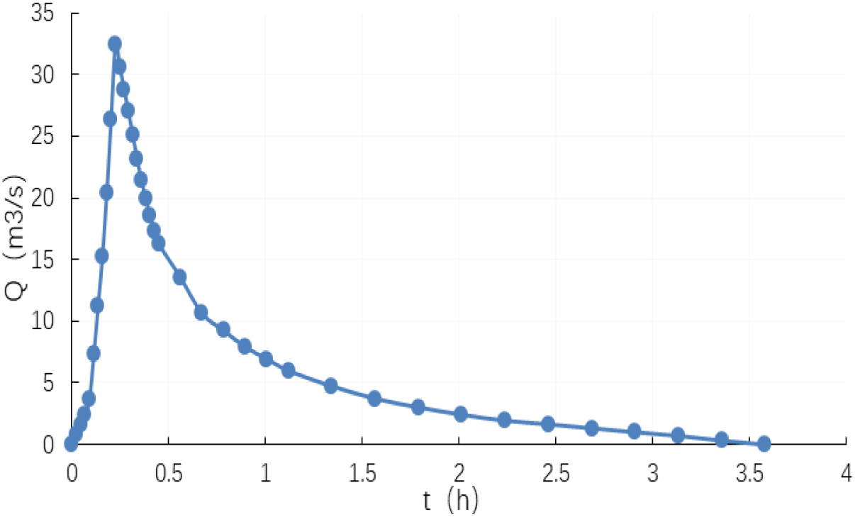
For the initial situation:
According to water balance, it can obtain that:
Calculation of the relationship between
Note: The above table
Calculation table of water balance (flood diversion)
The calculation process is shown in Tables 6 and 7, and the flood hydrograph and flood discharge hydrograph are shown in Fig. 3.
The conclusion is as follows:
(1) Required flood storage capacity
(2) Maximum discharge volume
Flood hydrograph and flood discharge hydrograph.
Calculation results of tailings pond flood regulation
The flood routing results of tailings pond are shown in Table 8, it is evident that the sedimentary beach surface of the tailings pond remains virtually unchanged following its closure. In the event of a design flood occurring once every 1000 years, where the flood rise value is 0.7 m, the minimum safe elevation is 2.0 m, and the minimum dry beach measures approximately 130 m. All of these measurements are in accordance with the relevant provisions and requirements specified in the Code for Design of Tailings Facilities (GB50863-2013) pertaining to the safety height of second-class tailings pond (not less than 1.0 m) and the safety beach length (not less than 100 m). Hence, the flood control safety of the tailings pond is guaranteed.
The design and implementation of the closed reservoir project for the decommissioned tailings pond can establish a robust foundation for its long-term safety and stability. However, long-term maintenance and management are necessary to uphold the safety and stability of the tailings pond over time.
The following are essential factors for safety maintenance and management of the tailings pond after closure:
Maintenance of the tailings pond stacking dam to ensure its safety and stability. Regular inspection of the flood drainage system to ensure its safety and smooth flow. Monitoring the maintenance of facilities to ensure their effectiveness and reliability. Precluding natural and man-made damage to the tailings pond. Performing maintenance on the dam body and the drainage ditch on the dam face following the closure of the tailings pond. Strict prohibition of storing water or flood without demonstration and approval. Illicit mining, digging, illegal construction, and illegal operations in tailings dams and warehouses are also prohibited. Without design demonstration and approval, the tailings pond after closure must not be used again or repurposed for other objectives, and the safety facilities in the reservoir must not be compromised when utilized for other purposes. Establishment of safety warning signs in conspicuous and hazardous locations within the reservoir area, along with the inclusion of six safety warning signs for the tailings pond.
This paper presents a method for closing a tailings pond by adding a flood discharge system (i.e., spillway), as well as plugging the existing overflow tower and drainage pipe. Additionally, flood control safety assessment is conducted by integrating flood routing of flood discharge facilities. The results of this study are as follows:
The flood regulation calculation results indicate that when encountering a design flood with a return period of 1000 years after the closure of the tailings pond, the safety superelevation and minimum dry beach length of the tailings pond meet the relevant provisions of the “Design Code for Tailings Facilities (GB50863-2013)”, which verifies the rationality and feasibility of the closure design scheme. The design and execution of closed tailings ponds have established a strong foundation for their enduring safety and stability. However, it is crucial to undertake essential maintenance and management measures to ensure the long-term safety and stability of these tailings ponds.
Footnotes
Acknowledgments
The authors acknowledge the General Project of Science and Technology Plan of Beijing Municipal Commission of Education (KM202310009005), the Project of Innovation and Entrepreneurship Training Program for College Students.