
Abstract
In recent years, wireless charging technology for electric vehicles has gained significant attention. To accurately analyze the distribution characteristics of the electromagnetic field during the wireless charging process of electric vehicles, a finite element-based electromagnetic analysis method was employed. Applied in the commercial simulation software, the electromagnetic environment of the resonant coil and electric vehicle model was simulated under high-power charging conditions, resulting in an overall electromagnetic field distribution for the electric vehicle. The results indicated that within the coil region, the magnetic induction intensity in the central area of the coil was zero, and it increased as the distance from the center of the coil grew. Outside the coil region, the magnetic induction intensity gradually decreased. The electric field intensity of the resonant coil was maximum in the central area of the coil, and it weakened as the distance from the center of the coil increased. When a magnetic shielding resonant coil was used, the electromagnetic field was confined between the shielding materials, and the magnetic field rapidly attenuated on both sides of the magnetic shield. The electromagnetic field energy of the electric vehicle body was mainly concentrated at the bottom of the vehicle near the coil. When the coil was located in the front of the car body, the maximum electric field intensity distribution in the car body was 8.50 V/m, and the maximum magnetic induction intensity was 0.024
Keywords
Introduction
To address the challenges posed by global temperature rise and frequent extreme climate conditions, China has proposed the dual carbon goals of peaking carbon emissions and achieving carbon neutrality. Electric vehicles, driven by their green concept of nearly zero emissions, have experienced rapid development. Consequently, wireless charging technology for automobiles has garnered increasing attention [1, 2]. With deeper research into wireless technology, electromagnetic safety concerns have attracted public attention. Electromagnetic radiation not only interferes with the normal electromagnetic environment within the human body, posing risks to human health, but also disrupts the proper functioning of surrounding precision instruments [3, 4]. Therefore, it is imperative to conduct research on the magnetic field distribution characteristics within the operating frequency range of the wireless charging area [5].
University of L ’Aquila, Italy, proposed a design method of active coil shielding, and studied the magnetic field generated by coil current during wireless charging [6]. The University of Michigan in the United States and Nanyang Technological University in Singapore respectively improved the wireless power transmission system to improve the electromagnetic field environment during wireless charging of electric vehicles [7, 8]. Shanghai Jiaotong University proposed to transform the charging control problem into a generalized Stackelberg game, and completed the electromagnetic signal detection and safety assessment around the wireless charging process of electric vehicles [9]. Nanjing University of Aeronautics and Astronautics and Hebei University of Technology study the working characteristics of wireless charging system for electric vehicles [10, 11]. On the basis of wireless charging of electric vehicles, the Hong Kong Polytechnic University and Nanjing University of Science and Technology analyzed the electromagnetic safety characteristics [12, 13]. Shin et al. reduce the electromagnetic field by adding a series of inductors to the wireless transmission system [14]. Wang et al. put forward a new type of coil topology, and analyzed its current and electromagnetic situation [15, 16]. Cheng et al. puts forward the method of S-PS resonance compensation for relay coil, and analyzes the influence of parasitic resistance on electromagnetic environment of wireless charging system [17]. Zhang et al. analyzes the electromagnetic field distribution of electric vehicle body and its influence on human safety [18]. Zhang et al. aiming at the energy encryption problem of dynamic wireless charging system of cluster electric vehicle, a reconfigurable capacitor compensation network is proposed and its electromagnetic field distribution is studied [19]. Wang et al. puts forward a new type of magnetic coupling mechanism which is suitable for long guide rail transmitting coil and has the characteristics of stable output and low cost, and studies the electromagnetic field of the new type of magnetic coupling mechanism [20]. An accurate time-domain model of the N-coil wireless charging system was established, and a bipolar transmitting coil array was constructed, and the electromagnetic field distribution of the charging system was studied [21, 22].
Currently, most existing literature predominantly focuses on assessing and studying the electromagnetic field environment of the resonance coil or the vehicle specific locations. There is limited research in the literature that comprehensively investigates the entire electric vehicle in high-power wireless power transfer systems. Due to the simplification of simulation models, there may be disparities between simulation results and the actual magnetic field distribution. Therefore, accurately measuring the size and distribution of the magnetic field in the surrounding space of electric vehicles is of crucial significance for the research on wireless power transfer.
This paper utilizes the commercial finite element software to establish models for both the vehicle structure and the charging coil. The Frequency Domain Electromagnetic Waves module is employed for simulating and analyzing the spatial distribution of electric and magnetic fields during high-power wireless charging of the entire electric vehicle and the resonance coil. And its distribution characteristics are thoroughly analyzed. The study provided basis for the formulation of relevant standards, drew relevant protection opinions, and promoted the development of electric vehicle industry.
Wireless charging principle of electric vehicle
Structure model of wireless charging system for electric vehicle
The structure of the wireless charging system for electric vehicles involves installing the transmitting end at a fixed position on or beneath the ground, while the receiving end is mounted on the chassis of the vehicle, as illustrated in Fig. 1.
Configuration of receiving and transmitting terminals of wireless charging system for electric vehicles.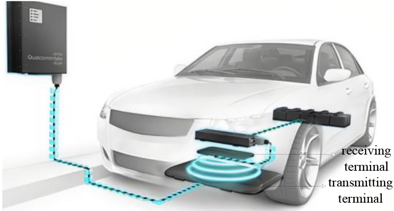
The internal structure of the receiving end and transmitting end of the wireless charging system for electric vehicles consists of a cover plate and coils, as shown in Fig. 2 [23].
Structure diagram of transmitter and receiver of wireless charging system for electric vehicle.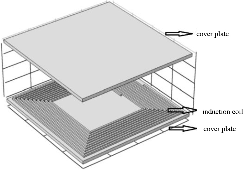
The receiving coil converts the received energy into direct current (DC) that can be stored by the electric vehicle’s battery pack through a high-frequency rectification and filtering circuit [24].
Generally speaking, the coil commonly adopts either a spatial cylindrical coil structure or a planar spiral coil structure, as depicted in Fig. 3.
Coil structure diagram.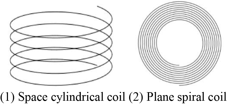
The simulation analysis in this paper is conducted using a planar circular spiral coil. The planar spiral coil is suitable for short-distance wireless power transfer systems, and this coil occupies a small space, making it convenient for installation.
This paper adopts a magnetic-coupling resonant charging system. The effective transmission distance of a magnetic-coupling resonant system is higher than that of an inductive-coupling system. Even when there is deviation between the transmitting and receiving coils, it still maintains a high level of transmission efficiency [25]. The principle and schematic diagram of the electric vehicle using a magnetic-coupling resonant charging system are illustrated in Figs 4 and 5.
Schematic diagram of wireless charging.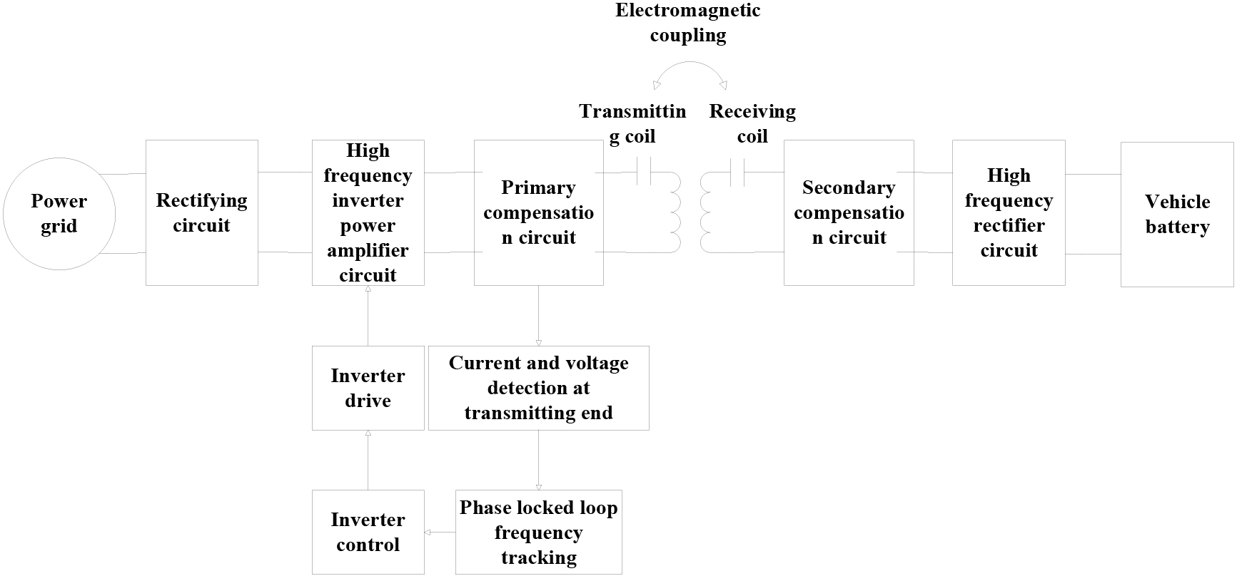
Schematic diagram of electric vehicle wireless charging.
The principle of the wireless charging system for electric vehicles involves the transformation of alternating current (AC) from the power grid into high-frequency alternating current through rectification, filtering, high-frequency inversion, and power amplification. Through the method of magnetic-coupling resonance, efficient transmission of electrical energy is achieved [26, 27].
In wireless charging systems, to prevent a decrease in system efficiency due to frequency mismatch, a device for detecting high-frequency alternating voltage and current is added to the wireless power transmission end. The phase-locked loop frequency tracking circuit controls the inverter control circuit to maintain stable frequency control, ensuring the stability of the system’s transmission efficiency. To reduce system leakage inductance and improve transmission performance, a reactive power compensation structure is added to the primary and secondary windings [28].
Finite element simulation principle of electromagnetic field
The electromagnetic analysis problem is essentially solving the Maxwell’s equations under given boundary conditions. The following are the differential forms of the Maxwell’s equations:
When using the system of equations to solve practical problems, it is also necessary to consider the influence of the medium on the electromagnetic field. In a uniform isotropic medium, the relationship between various physical quantities of the electromagnetic field and the characteristics of the medium is as Eqs (5)–(7):
In the above equation,
To simplify the computations related to the electromagnetic field, magnetic vector potential A and scalar potential
Substituting Eqs (5)–(9) into Eqs (1) and (3), we obtain the partial differential equation for calculating electromagnetic fields, as Eqs (10)–(12):
In the equation
The wireless charging system for electric vehicles mainly consists of two parts: first, the modeling of the electric vehicle, and second, the modeling of the wireless charging coil.
It is necessary to simplify the model in the process of vehicle electromagnetic simulation modeling to ensure that the input data can be effectively used by the computer. The complex model will also increase the calculation amount, distort the grid and produce wrong simulation results. Therefore, in the process of electromagnetic simulation modeling, it is necessary to simplify the electromagnetic calculation model as much as possible, so as to establish a simple and effective model. Since interior components such as seats, steering wheels, and interior materials are made of dielectric materials, their impact on electromagnetic field calculations is minimal and can be neglected. Small cavities and seams on the vehicle body are filled, and the body materials such as the chassis and pillars are treated as good conductors. Through these simplifications, a simplified three-dimensional model of a benchmark car body was established based on the three-dimensional digitized model of the benchmark car body, as shown in Fig. 6, with geometric dimensions of 4.2 m
The resonant coil used for wireless charging in automobiles adopts a circular ring structure with copper material, and the material for the square-shaped board is polytetrafluoroethylene (PTFE) with a thickness of 1 cm. The coil is illustrated in Fig. 7.
The resonant coil used in this paper adopts a symmetrical structure, with an operating frequency of 10 MHz, and the distance between the two coils is 30 cm [29]. The specific physical parameters of the coil are shown in Tables 1 and 2.
Resonant coil related parameters
Resonant coil related parameters
Resonance coil performance parameters
Electric vehicle model.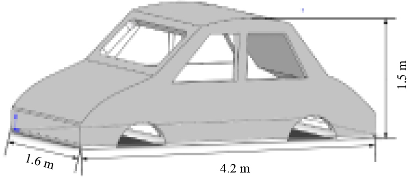
Resonant coil model.
Based on the established model and simulation software, simulations were conducted to analyze the electromagnetic field distribution in the wireless charging model for electric vehicles. When the electric vehicle is in a charging state, not all the energy can be received by the receiving coil; some electromagnetic energy will leak.
To confine the exchange of electric energy within a limited area, improve coupling efficiency, and reduce environmental issues caused by electromagnetic radiation, high-permeability shielding materials, specifically ferrite magnetic shielding plates, were added to both the transmitting and receiving ends. Two simulation models with different structures, as per the provided coil parameters, were constructed, as shown in Fig. 8.
Simulation geometric model diagrams of structures. 
Simulation analysis of resonant coil electromagnetic field
Magnetic field analysis
Through finite element simulation software, simulation analysis was conducted on two coil structures. The spatial magnetic induction intensity distribution diagrams for the resonance coupling models without magnetic shielding structure and with magnetic shielding structure can be obtained, as shown in Fig. 9.
The transmitting coil and receiving coil are placed parallel and aligned, located respectively on the XOY plane at
Spatial distribution diagram of magnetic induction intensity of two structures.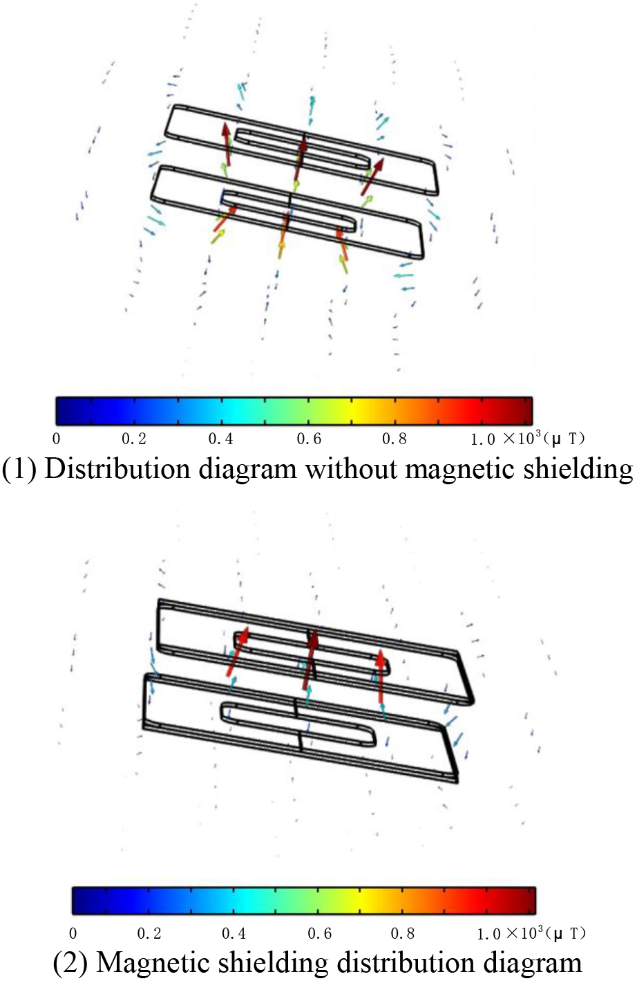
An axial three-dimensional cross-sectional plots were created along the z-axis at points (0, 0, 20) and (0, 0, 40), and radial three-dimensional cross-sectional plots were generated along the Y-axis at points (0,
Axial and radial spatial magnetic induction intensity distribution diagram under two structures.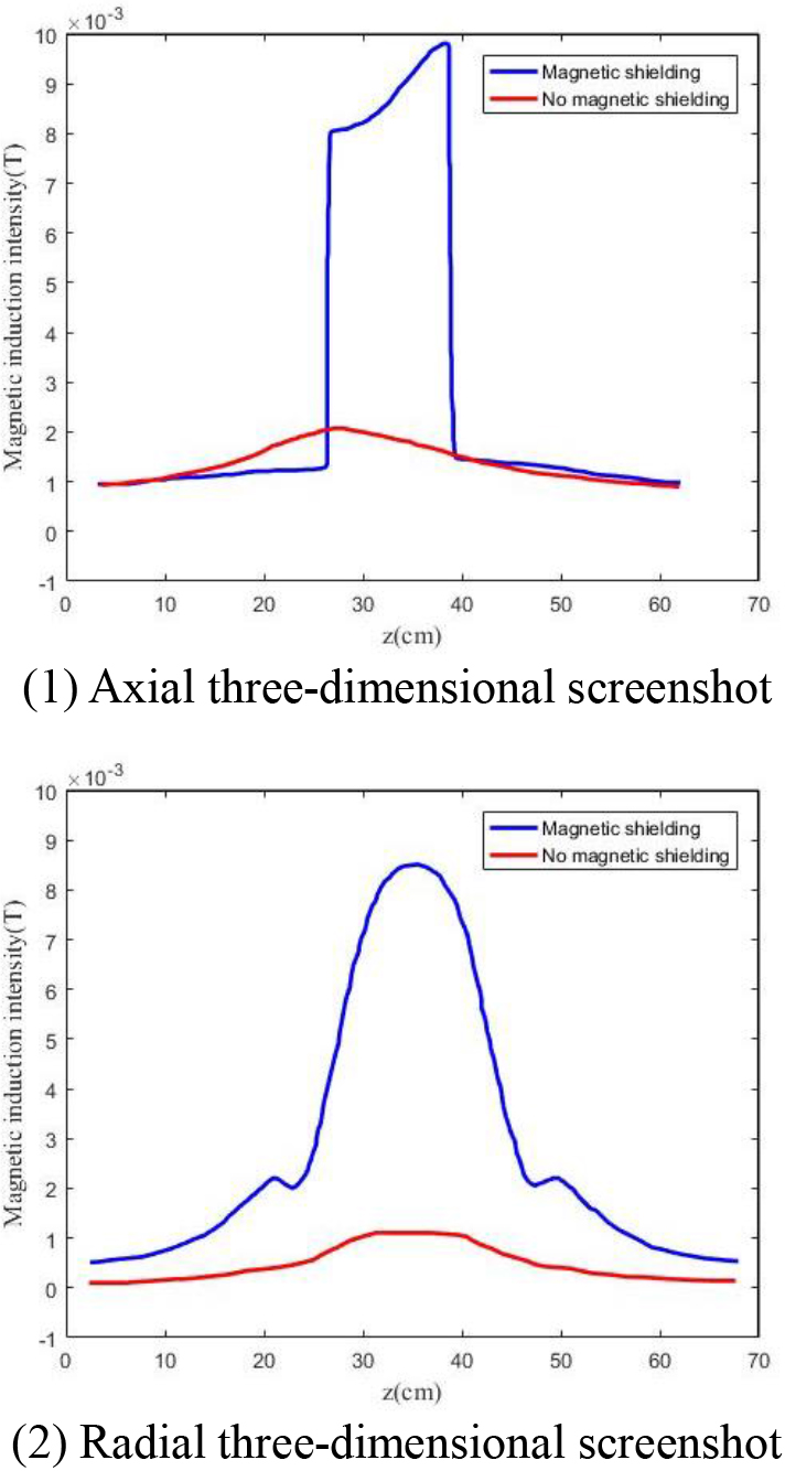
From Fig. 10, it can be observed that after the addition of magnetic shielding, the coil with a shielding plate generates more magnetic flux lines, which pass through the receiving coil and then return to the transmitting coil. The quantity of magnetic flux lines in the coupling region between the two coils significantly increases. The magnetic induction intensity in the coupling region between the coils is noticeably enhanced. The electromagnetic field is mainly concentrated in the space between the transmitting and receiving coils. After the addition of magnetic shielding, the magnetic field attenuation above and around the magnetic shield accelerates. The introduction of magnetic shielding helps to increase the coupling coefficient between the two coils and can reduce the radiation of the magnetic field outward.
In order to visually depict the magnetic field distribution around the resonant coils more intuitively, streamline plots of different cross-sections of the model were generated. The cross-sectional magnetic field distribution streamline plots of the YZ and XZ planes for an electric vehicle wireless charging system with a system frequency of 85 kHz and an output power of 15.2 kW are shown in Fig. 11.
Cross-sectional view of magnetic field distribution in electric vehicle charging space.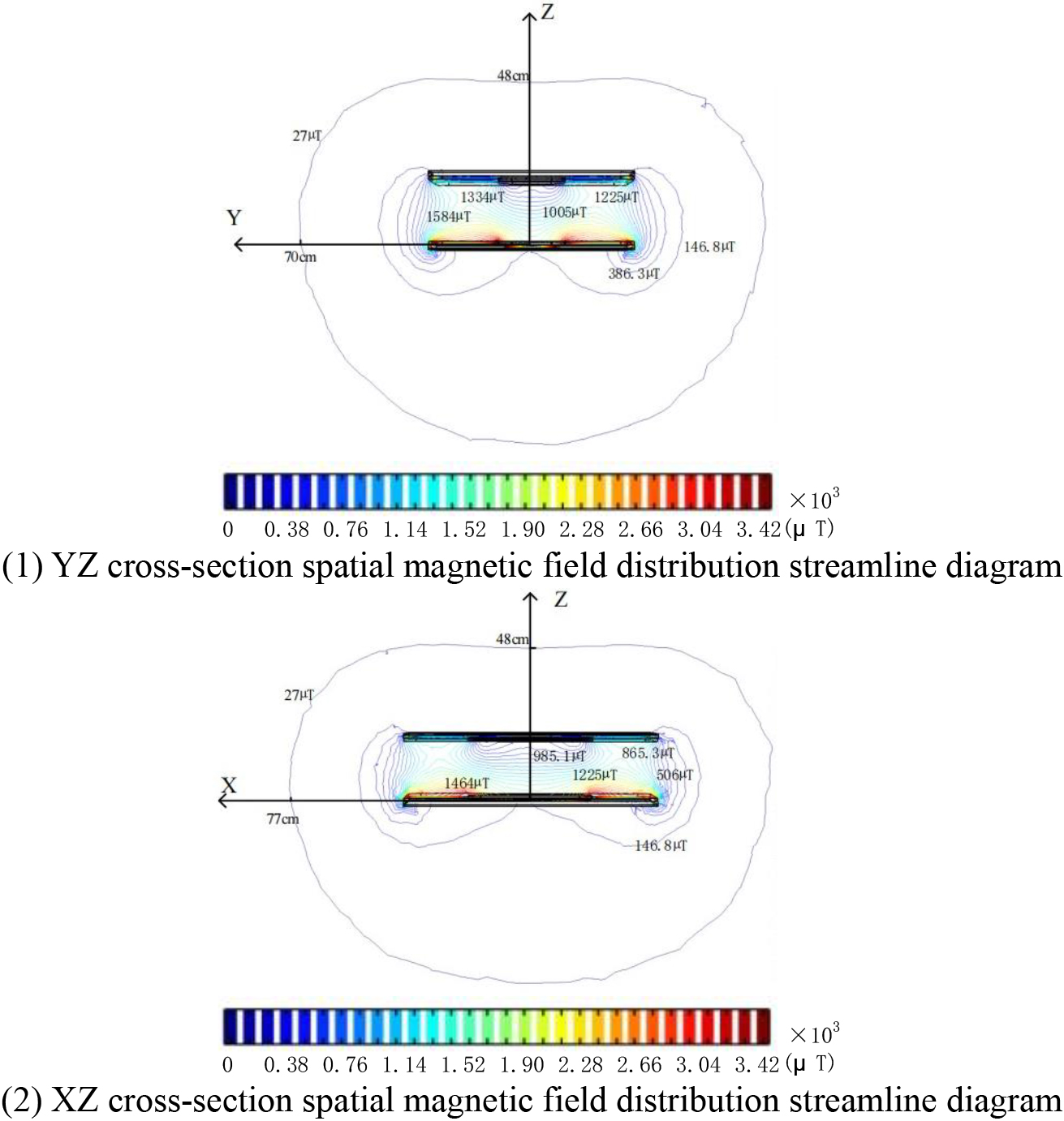
The electromagnetic field of the wireless charging system for electric vehicles is mainly concentrated in the space between the transmitting and receiving devices. Due to the magnetic shielding on both the transmitting and receiving devices, the internal magnetic field within the charging system decays rapidly, while the external magnetic field decays more slowly. Additionally, the farther away from the source, the slower the decay of the magnetic field, as shown in Fig. 12.
Magnetic field distribution diagram on the x-y plane at the back of the receiving coil.
Magnetic field intensity distribution on the cross-section before and after shielding.
XOY plane electric field intensity distribution of coil resonator before and after shielding.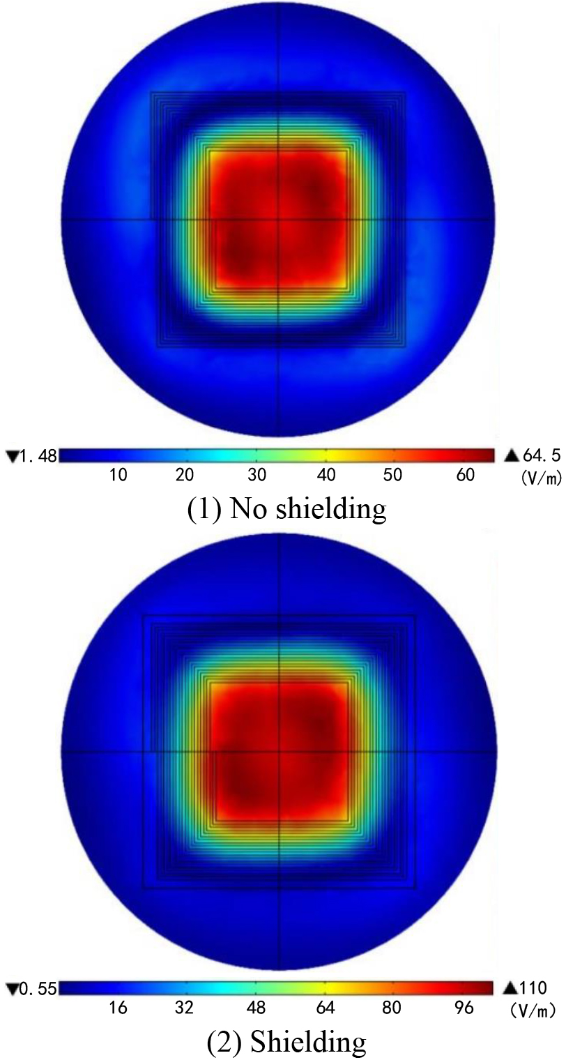
Another three-dimensional cross-sectional line was selected, with the starting point at (0,
Boundary conditions and volume meshing were set for both the shielded and unshielded models. Simulation analyses were conducted on the XOY plane at
YOZ plane electric field intensity distribution of coil resonator before and after shielding.
Select another three-dimensional section line with the starting point of (0,
Electric field intensity distribution on the cross-section before and after shielding.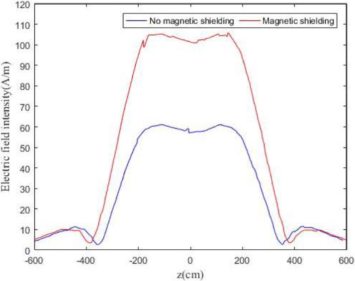
Section 1 (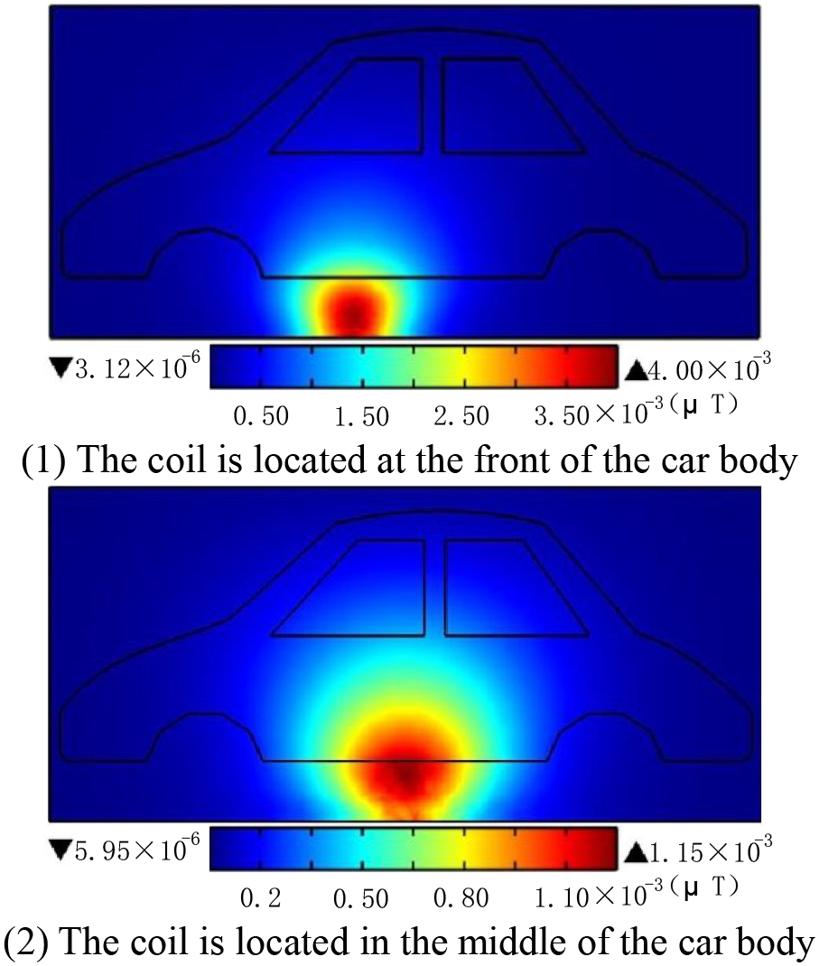
Section 2 (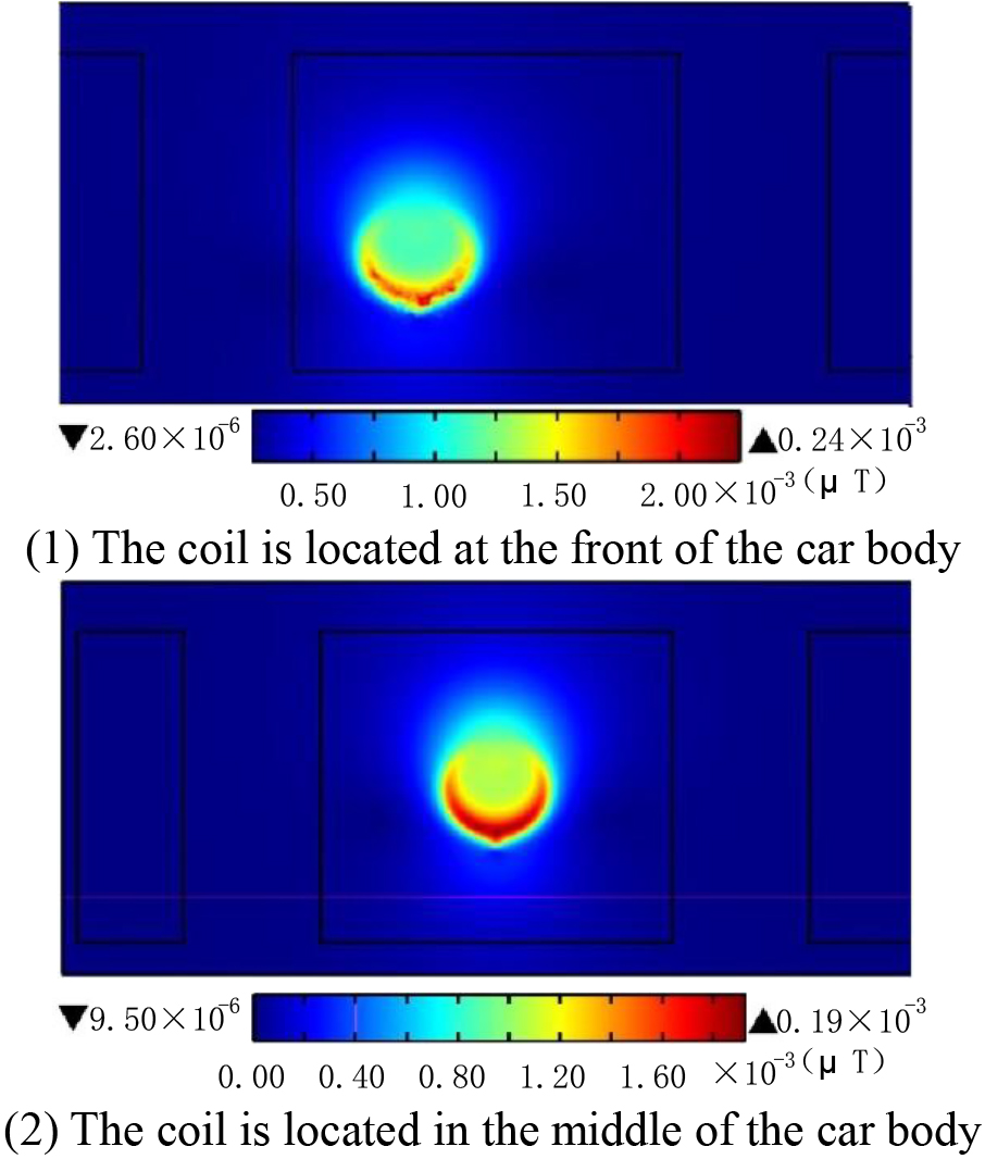
As observed from Fig. 16, before shielding, there is a certain level of electric field distribution on both sides of the resonant coil. However, after shielding, the electric field on both sides significantly decreases. Moreover, the addition of the shielding material increases the electric field intensity between the two coils, effectively constraining the spatial distribution of the electric field and concentrating it between the two coils.
Characteristics of the electric field after magnetic shielding on the coils: The electric field between the two coils exhibits symmetry along the cross-sectional direction; the electric field is large near the coils and decreases as one moves away from the coils; the electric field decays relatively quickly with distance.
Section 1 (
Section 2 (
Magnetic field analysis
An analysis was conducted on the magnetic field generated around the car during wireless charging, with a cross-section taken on the driver’s side of the vehicle as Section 1 (
From Fig. 17, it can be observed that the energy is mainly concentrated in the transmitting coil. The magnetic induction intensity values decrease progressively from the inside to the outside of the coil. As the height increases, the magnetic induction intensity values decrease. The values are greater at the location of the excitation source compared to other parts of the coil. With increasing distance, energy attenuation occurs rapidly, and the energy distribution at other positions on the vehicle body is minimal. It can be seen that when the coil is located at the front of the vehicle, the maximum magnetic induction intensity is 0.004
Taking the bottom plane of the car (
From Fig. 18, it can be seen that when the coil is located at the front of the vehicle, the maximum magnetic induction intensity is 0.024
Electric field analysis
The previous analysis focused on the magnetic field distribution in Sections 1 and 2. Next, an analysis is conducted on the electric field generated around the car during wireless charging. The electric field intensity slice diagram for Section 1 is shown in Fig. 19.
From Fig. 19, it can be observed that the energy is primarily concentrated around the transmitting coil. As the height increases, the electric field intensity significantly decreases. The electric field intensity at the edge of the coil is greater than in other areas. When the coil is located at the front of the vehicle, the maximum electric field intensity distribution within the vehicle is 8.50 V/m. When the coil is in the middle of the vehicle, the maximum electric field intensity is 2.31 V/m. Comparatively, the former value is greater than the latter.
The electric field distribution of Section 2 is shown in Fig. 20.
From Fig. 20, it can be seen that when the coil is located at the front of the vehicle, the electric field distribution is primarily concentrated at the driver’s position, with other areas of the vehicle being less affected. The farther away from the coil, the smaller the impact of the electric field. When the coil is located at the front, the maximum electric field intensity is 27.1 V/m, and when it is in the middle of the vehicle, the maximum electric field intensity is 22.5 V/m. Comparatively, the former is greater than the latter.
Conclusion
This paper, by establishing the structural model of a wireless charging system, considered simulation on resonant coils and electric vehicle models under different transmission frequencies and power conditions. The analysis leaded to the following conclusions:
Within the resonant coil region, the magnetic induction intensity increased with the distance from the center of the coil and was zero at the central position. Outside the resonant coil region, the magnetic induction intensity decreased as the distance from the coil increased, with the intensity weakening as the distance grew. The electric field intensity of the resonant coil was maximum in the central area of the coil and decreased as the distance from the coil increased.
When the coil was located in the front of the car body, the maximum electric field intensity distribution in the car body was 8.50 V/m, and the maximum magnetic induction intensity was 0.024
The analysis results of the electromagnetic field intensity on the electric vehicle body indicated that the energy was primarily concentrated at the bottom of the vehicle near the coil. As the distance from the coil increased, the electromagnetic field intensity values decreased.
Footnotes
Funding
The work was financially supported by Science and Technology Projects from State Grid Corporation of China (5200-202113091A-0-0-00).