
Abstract
In order to improve the communication quality and transmission rate of WLAN, the key technologies of smart antenna in WLAN based on adaptive array are proposed. The adaptive array is used to suppress the WLAN interference signal, and the feedback from the output is used to adjust the weight loaded on the signal, and the optimal weight corresponding to the linear constraint minimum variance is obtained to achieve beamforming optimization. On this basis, the optimal antenna selection algorithm and the sub-optimal antenna selection algorithm are designed, and the sub-channel matrix with the maximum capacity can be obtained by repeated iterative calculation, so as to realize the smart antenna selection and further optimize the performance of WLAN. Experimental results show that the smart antenna signal has 100% coverage in WLAN compared with conventional methods. When the transmission rate is greater than 35 mb/s, the delay of the study method is not jitter compared to the contrast method. When the transmission rate is greater than 35 mb/s, the packet loss rate of the proposed method remains stable, while the packet loss rate of the two comparison methods begins to increase. When the transmission rate is greater than 12 mb/s, the throughput of the proposed method is more stable than the other methods. In conclusion, this method has the characteristics of large signal coverage, low delay, low packet loss rate and high throughput, and can be widely used in practice. The contribution of this study is that the weight of the antenna array can be dynamically adjusted through the adaptive algorithm, thus optimizing the quality of the received signal and improving the receiving sensitivity.
Introduction
A Wireless local area network (WLAN) is a local area network that uses radio waves as the transmission medium to replace some or all of the transmission media in a wired LAN [1]. It uses geomagnetic waves in the air to replace the cable medium of the traditional wired network for transmission, thus getting rid of the bondage of the network cable and providing all the functions of the traditional wired network without the use of traditional media. In WLAN, smart antenna technology plays an important role in improving network performance and coverage due to its excellent spatial domain filtering performance and anti-interference capability [2, 3, 4]. The adaptive array is the core component of smart antenna technology, which can realize dynamic tracking and optimization of wireless signals, so as to maintain good communication quality in the complex and changeable wireless environment. However, with the rapid development of wireless communication, people’s performance requirements for WLAN are constantly improving, which makes the application of adaptive array technology in WLAN face more challenges. For example, how to optimize the configuration of the antenna array, how to improve the transmission rate of the signal and how to reduce the interference have become the focus of research. Therefore, the key technology of WLAN smart antenna based on adaptive array is proposed, and the application of signal detection technology in WLAN is discussed. The innovation of this research is to combine the optimal antenna selection algorithm and the suboptimal antenna selection algorithm on the basis of adaptive beamforming technology, so as to optimize the signal reception quality. Through this research, we hope to provide a more comprehensive and effective solution for the adaptive array technology in WLAN, so as to further promote the development of wireless communication technology.
Literature review
Aiming at the key technology of smart antenna, which is an important research topic, reference [5] in order to meet the data transmission demand of large-scale multiple input multiple output (MIMO) system and reduce system energy consumption, a smart antenna selection and power distribution method based on quantum chemical reaction optimization is proposed. The model of smart antenna selection and power distribution is established according to the user transmission requirements of large-scale MIMO system in different time periods, and its maximum energy efficiency equation is derived. In order to effectively solve the nonlinear and multi-constrained hybrid optimization problem, a quantum chemical reaction optimization algorithm was designed combining the advantages of quantum computing and chemical reaction optimization mechanism, and the optimal antenna selection and power distribution scheme could be obtained. In reference [6], the traditional beamforming algorithm directly processes the received data of all antenna array elements, resulting in large computational complexity and slow convergence speed, and it is unable to receive the target signal in real time and effectively. In order to reduce the computational complexity and improve the convergence speed, a reduced rank adaptive beamforming algorithm is proposed for low complexity smart antenna target signal reception. The proposed algorithm is based on the random gradient method. The joint iterative optimization is used to reduce the rank of the signal, and the weight vector and the projection matrix are iterated with each other to achieve convergence. At the same time, the set membership method can update the data selectively, improve the step size, improve the convergence speed, and analyze the computational complexity and convergence performance. Reference [7] proposed a smart antenna selection and power distribution method based on quantum chemical reaction optimization. The model of smart antenna selection and power distribution is established according to the user transmission requirements of large-scale MIMO system in different time periods, and its maximum energy efficiency equation is derived. In order to effectively solve the nonlinear and multi-constrained hybrid optimization problem, a quantum chemical reaction optimization algorithm was designed combining the advantages of quantum computing and chemical reaction optimization mechanism, and the optimal antenna selection and power distribution scheme could be obtained.
In the relevant research of WLAN smart antenna based on adaptive array, Abdulkawi proposed a communication system suitable for Internet of Things applications in desert areas, which adopted a developed six-element array, and experiments showed that the system has the requirement of extending the coverage area of the local area network [8]. Oliveira et al. proposed a MIMO antenna structure with two different elements, and used Ansoft HFSS software for simulation and design, and the experiment proved that the simulation results of the method were consistent with the measured structure [9]. The problem of existing adaptive array processing algorithms is that they will introduce distortion and bias errors in phase carrier phase measurement. Therefore, Li’s team proposed a robust phase compensation technology to reduce phase distortion. Experiments show that this technology is suitable for power inversion adaptive antennas and can be extended to various adaptive antennas [10]. In order to meet the increasing requirements of high capacity, wide coverage, low latency and strong robustness of future sixth-generation (6G) wireless communication, Xiao’s team introduced the technical potential and challenges of antenna array support space, discussed the structure and design of antenna array, and finally proposed the future research direction of antenna array support space/air/ground communication and network [11]. Traditional detection and suppression algorithms are only used to eliminate spoofing signals, which may lead to insufficient number of positioning satellites. Therefore, Fan team proposed an adaptive spoofing suppression algorithm based on multiple antenna arrays. Experiments show that all these methods have good positioning performance and can identify and eliminate spoofing earlier and faster [12]. In order to detect and mitigate interference and deception before the deployment of GNSS receiver, Zhang’s team proposed a two-stage interference suppression scheme based on antenna array. Experiments show that this scheme not only effectively inhibits interference and deception, but also maximizes the power of real signals [13].
But the above technology of smart antennas applied to WLAN of small signal coverage, high latency and packet loss rate is high and the low throughput, so in order to solve these problems existing in the method as the research target, based on the adaptive array are studied the key technologies of smart antenna in WLAN, and in the actual application effect of this method are verified.
Key technologies of smart antenna in WLAN
Beamforming optimization based on adaptive array
The principle of smart antenna technology is to make a set of antenna and the corresponding transceiver according to certain order and incentive, using the wave interference principle can generate strong directional radiation pattern, if the use of digital signal processing method in the baseband processing, make the radiation pattern adaptive to main lobe pointing users to wave direction, can achieve improve signal than done, the purpose of reducing transmitting power and improving coverage [14, 15]. It guides the radio signal in a specific direction, generates a spatial directional beam, aligns the main beam of the antenna with direction of arrival (DOA) of the user signal, and the side lobe or zero trap aligns with the DOAl of the interference signal, so as to achieve the purpose of fully and efficiently utilizing the signal and deleting and suppressing the interference signal. In addition, it can automatically track changes of users and application environment, so as to effectively suppress interference, extract user signals, and improve link performance and system performance. At the same time, the smart antenna technology takes advantage of the difference of signal space characteristics among various mobile users, and receives and transmits signals from multiple mobile users in the same channel without mutual interference through array antenna technology, making the utilization of radio spectrum and signal transmission more effective. From the direction diagram to distinguish, antennas are mainly omni-directional antenna and directional antenna [16, 17]. The shape of the covered area in these two ways is fixed. The core of smart antenna technology research is beamforming algorithm, which determines the instantaneous response rate and the complexity of circuit implementation. Therefore, it is most important to select a good algorithm to realize the intelligent control of beam, and to find a truly fast convergence and excellent performance adaptive algorithm is the key of this research. Adaptive antenna array is one of them. The schematic diagram of adaptive antenna array is shown in Fig. 1.
Schematic diagram of adaptive antenna array.
Adaptive antenna array is a closed-loop feedback control system consisting of an antenna array and a beamforming device. The rf analog signals received on each array are processed by the RF front-end equipment, then converted down to the baseband, and processed in the digital domain after A/D transformation. The complex weighting vector of each channel is determined by the adaptive algorithm. Therefore, the core of smart antenna is its beamforming device, namely adaptive processing algorithm [18]. The beam pattern of the antenna can be changed by changing the weight vector through algorithmic programming, so the smart antenna is also called software antenna. The adaptive array strives to suppress the interference signal and uses the feedback from the output to adjust the weight applied to the signal to optimize certain parameters or certain equations, achieving beamforming optimization. A narrowband adaptive system with external disturbance can be expressed as:
Where,
Where,
Where,
The least mean square error algorithm minimized the mean square error between the beamforming output and the reference signal by selecting weight [19], and the specific formula is as follows:
Where,
Substitute Eqs (3) and (4) into Eq. (16) to obtain:
Among them:
Equation (17) is derived into an equation with a common Eigen problem. The optimal weight of the maximum signal-drying ratio can be obtained by solving the following equation:
Where,
The minimum variance constrains Eq. (21) by the following constraints:
Or:
The variance of the output signal can be expressed as [20]:
Minimizing Eq. (24) constraining Eq. (22) is the same as minimizing
Among them,
Meanwhile, the linear constraint minimum variance has more than one constraint on Eq. (21). If I have a fixed interference signal. And knowing its arrival direction
This formula is a linear constraint.
If there are now
Where,
The beamforming optimization is realized by combining the optimized weight.
In the communication environment between single AP and multiple users, by comparing with omnidirectional antenna, and considering the correlation, antenna number, SNR and other factors, a smart antenna selection algorithm is designed to improve system capacity and performance.
Considering the WLAN environment based on smart antenna, the WLAN system model is as follows: The AP is configured with
Let
System input and output relationship.
In order to make the antenna selection and user mode as optimal as possible, a
In the downlink single AP and multi-user environment, the CSI collected by AP is integrated into a large CSI matrix. In omnidirectional antenna mode, AP randomly selects a certain mode of each user for data transmission, which is likely to lead to the whole system not working in the optimal state for a long time and the system capacity is low. Therefore, in order to improve the performance of WLAN system, the core of smart antenna lies in the design of antenna selection algorithm [22, 23].
The joint antenna selection algorithm is to select the antenna at both ends of the receiver and receiver at the same time, or select one end of the receiver and receiver first, and then select the other end to maximize the capacity of the system. At present, among the existing joint selection algorithms, the optimal antenna selection algorithm is widely used, and the selected capacity is the best, but its disadvantage is that with the increase of the number of antennas, the computation increases sharply and the complexity becomes larger and larger.
(1) Optimal antenna selection algorithm
It is assumed that
Where,
Where,
(2) Suboptimal antenna selection algorithm
Time optimal antenna selection algorithm is divided into decreasing antenna selection algorithm and the increasing antenna selection algorithm, decreasing antenna selection algorithm from the given target antenna number, selected from the receiving antenna channel matrix of rows and columns respectively corresponding to the transmitting antenna and receiving antenna, decreasing antenna selection algorithm is aimed at every step to get rid of matrix of the smallest capacity contribution in a row or column.
The purpose of the increasing antenna selection algorithm (ISSA) is similar to that of the decreasing algorithm, which selects the row or column with the largest capacity contribution from the channel matrix through continuous iteration until all antennas are selected.
Specifically, firstly, the antenna with the maximum channel capacity is selected from the large matrix:
When the
Therefore, it can be inferred that:
The subchannel matrix with maximum capacity can be obtained by repeated iterative calculation.
The selection of submatrices adopts the greedy idea, that is, the matrix whose target matrix is
Flow chart of greedy algorithm in orthogonal projection.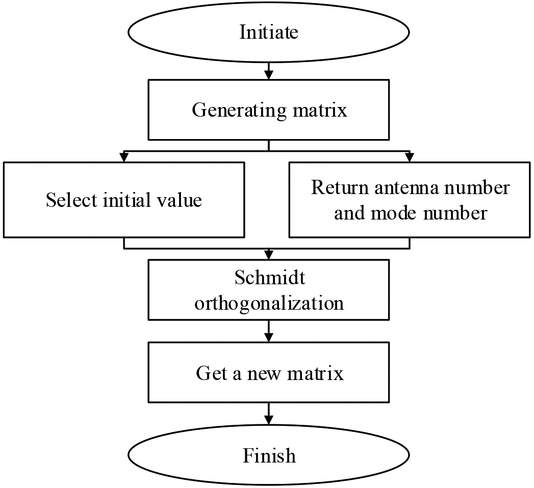
Step 1: Generate a matrix of
Greedy algorithm in each iteration is local optimal solution, and the resulting is not necessarily the global optimal, but it is because of greedy algorithm does not consider the overall situation in May, in the process of the user to select, omitted to find the optimal solution and end all can take a lot of time, which to a certain performance loss in exchange for a low algorithm complexity. The complexity analysis of the algorithm is as follows: In antenna side, first of all to iterate through all of the antenna pattern, complexity of
By using the adaptive array technology, the spatially selective receiving ability of the antenna array can be used to improve the intensity of the received signal, thus increasing the signal-to-noise ratio between the signal and the background noise. This can reduce the influence of multipath fading and improve communication quality and reliability. In order to improve the SNR, the research can be carried out in the following ways: firstly, increase the gain of the receiving antenna to enhance the intensity of the received signal, and then reduce the noise factor of the receiving system to reduce the influence of the system noise; Finally, the transmission link is optimized and better signal coding and modulation methods are adopted to improve the reliability and anti-interference ability of the signal. Depending on the specific application scenario and requirements, different environmental assumptions may be different. For the operation method of the environment assumption, the appropriate antenna design and configuration parameters can be selected according to the specific needs and circumstances. For indoor environments, indoor coverage antennas can be considered to avoid the influence of indoor barriers on signals. For outdoor environments, select an appropriate outdoor antenna according to the specific application scenario, and consider the antenna directivity and gain parameters. For the complex multi-path fading environment, antenna array or multi-antenna technology can be considered to improve the signal reliability and anti-interference ability.
Experimental scheme
WLAN for suburban connectors and rural users, the main way is to use WLAN AP
Smart antenna parameter settings
Smart antenna parameter settings
AP2400-OP outdoor type (0500N12P25S) CPE is a wireless terminal access equipment for receiving WLAN signals. Table 1 shows the indicator status of AP2400-OP outdoor CPE.
Indicator status of AP2400-OP outdoor CPE
The advantages of JINGxin AP2400-OFTIII WLAN base station are as follows:
Wide coverage: the effective coverage radius of traditional outdoor high-power AP is 300–500 m, and the effective coverage radius of Jingxin III WLAN base station is 800–1000 m under visible condition. Compared with traditional AP, it has more advantages in coverage and can achieve high-quality coverage of the target area. High throughput of the machine: Type III WLAN base station uses 802.11n technology, the overall throughput of the equipment is 60–80 Mbps, while the throughput of traditional 802.11g AP is 25 Mbps, the overall throughput of type III base station is twice that of 802.11g AP, which reflects the characteristics of high throughput of a single device and more concurrent users. Use high-gain directional MIMO smart antenna to further improve link gain and coverage; The directional antenna of Jingxin WLAN base station adopts 15D Bi high-gain MIMO smart antenna, which greatly improves the uplink and downlink gain (currently, the antenna gain of traditional outdoor AP is 10-12D Bi). The vertical beam width of the WLAN base station antenna is adjustable to Flexible and fast installation and deployment: Jingxin WLAN base station can flexibly adjust the horizontal orientation and pitch Angle of the antenna to achieve optimal coverage of the target area.
The equipment is installed on the pole of THE C network tower, and the planned coverage area is the road and household within 1 km from the direction of the Docking station. The test position is used with CPE (uplink signal enhancement equipment). The test tool mainly uses a Think Pad T410 test computer, an Inter® WI-FI Link 1000 BGN wireless network card, and a Wirelessmon test software.
Comparison of coverage and delay under different methods
The method in this paper, the reference [5] method and the reference [6] method in WLAN are compared, and the results are shown in Fig. 4.
Comparison of smart antenna signal coverage with different methods.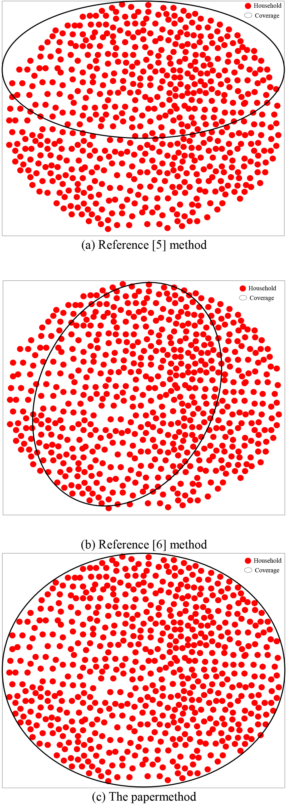
By analyzing the data in Fig. 3, it can be seen that after the application of the reference [5] method, the smart antenna in the WLAN only covers half of the research area, resulting in the decline of communication quality in the uncovered research area. Therefore, the practical application effect of this method is not good. Compared with the reference [5] method, reference [6] method applications, smart antenna in WLAN coverage about one-third of the study area, improved range of smart antenna signal, but there is smart antenna signal uncovered part of the study area, this area of the communication quality is not high, application effect is poorer. Compared with the reference [5] method and the reference [6] method, the smart antenna signal in WLAN can cover all research areas after the application of the method in this paper, ensuring that all residents in the research area can maintain normal communication, and the practical application effect is good. This is because the smart antenna of the adaptive array is able to focus the signal within a specific area, thereby expanding the coverage of the network. By dynamically adjusting the beam shape, smart antennas can reduce the scattering and attenuation of signals, thus providing wider wireless coverage.
The time delay of WLAN in the application of the method in this paper, the reference [5] method and the reference [6] method is compared, and the results are shown in Fig. 5.
Delay comparison results of different methods.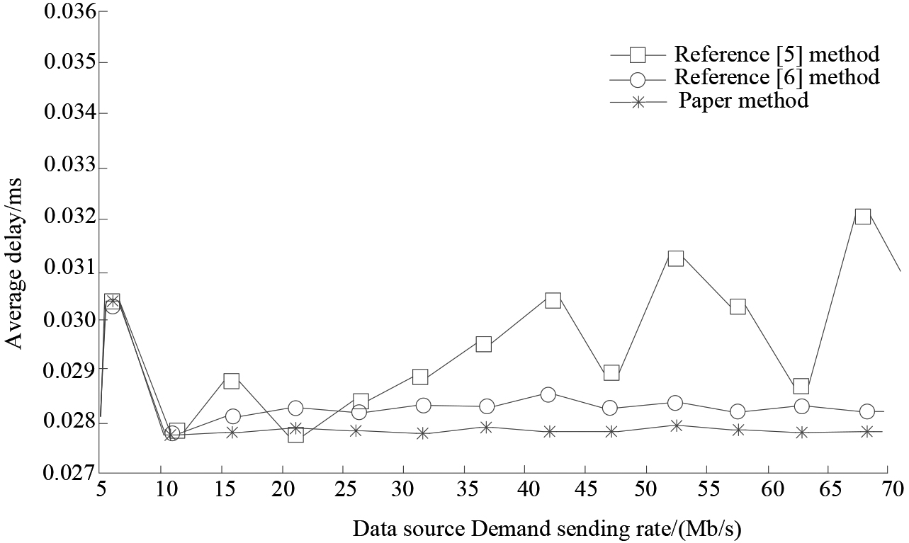
When the transmission rate is 6–31 Mb/s, the delay performance of the method in this paper, the reference [5] method and the reference [5] method is similar, indicating that the WLAN link status is good at this stage, and no congestion link appears. When the transmission rate exceeds 32 Mb/s, the delay of the reference [5] method begins to increase. When the transmission rate is greater than 35 Mb/s, the delay of the reference [5] method produces large jitter and the network performance begins to decline. Compared with the jitter of the reference [5] method, the delay of the method in this paper is basically no jitter, while the delay of the reference [6] method is between the two. This is due to the study of adaptive arrays of smart antennas that can optimize signal transmission by controlling antenna orientation and beam shape. It improves signal strength and quality by reducing signal attenuation and interference. This can significantly improve data transfer speeds for users, reduce latency and improve network reliability. The experimental phenomena in line with expectations, as a result of reference [5] the design of the method itself, when a link when heavy load and the data flow cannot be load is lighter and not switch to link congestion on the path of envoys point switch buffer queue increase thereby, increases the packet delivery delay, packet loss phenomenon, the network performance degradation; However, the reference [6] method can only be triggered when the flow is generated in the link. In contrast, the proposed method can control the time delay within the effective range, and is generally stable without jitter, showing certain advantages.
The packet loss rate test was carried out in the same experimental environment. The comparison results of WLAN packet loss rate after the application of the method in this paper, the reference [5] method and the reference [6] method are shown in Fig. 6.
Packet loss rate comparison results of different methods.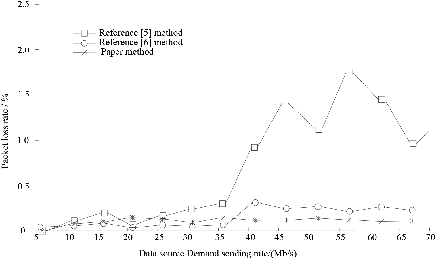
When the data source sending rate is lower than 5 Mb/s, the method in this paper, the reference [5] method and the reference [6] method do not produce packet loss. When the transmission rate is 5–35 Mb/s, the performance of the method in this paper, the reference [5] method and the reference [6] method is similar. However, when the transmission rate is greater than 35 Mb/s, the packet loss rate of the method in this paper remains stable, while the packet loss rate of the reference [5] method and the reference [6] method both begin to increase. When the transmission rate is 56 Mb/s, the packet loss rate of the reference [5] method reaches the peak. As for the reference [6] method, when the transmission rate is 42 Mb/s, the packet loss rate decreases and remains stable. To delay in section 3.2.2 tests, when sending rate is greater than 35 Mb/s, reference [5] method all have great jitter delay, network performance began to decline, the reason is that as the load increases, link congestion packet loss rate began to increase, when the source end into the WLAN congestion problem to solve, so packet loss rate began to fall again, such repetition causes the packet loss rate jitter of the reference [5] method.
The throughput comparison results of WLAN after the application of the method in this paper, the reference [5] method and the reference [6] method are shown in Fig. 7.
Throughput comparison results of different methods.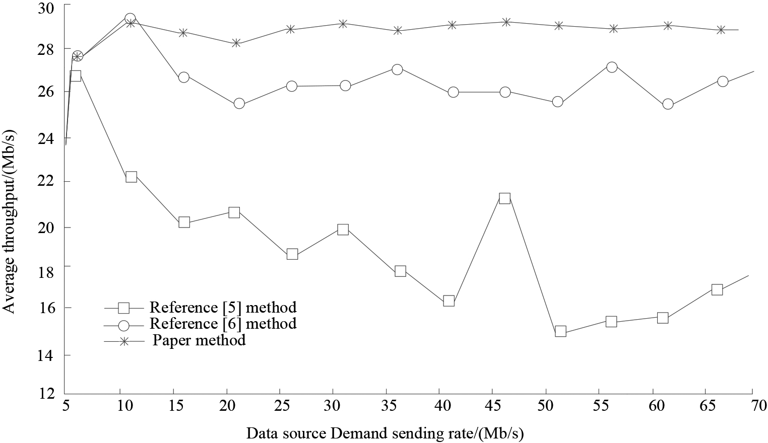
At the beginning of the experiment, the throughput of the method in this paper, the reference [5] method and the reference [6] method all increased rapidly after the application of the method. However, the throughput of the reference [5] method began to decline when the transmission rate was 6 Mb/s, and the overall jitter was large. When the transmission rate is 5–11 Mb/s, the performance of the reference [6] method is comparable to that in this paper. When the transmission rate is greater than 12 Mb/s, the throughput of the reference [6] method begins to decrease. When the transmission rate is greater than 22 Mb/s, the throughput of the reference [6] method tends to be stable. The adaptive array smart antenna can adjust the antenna direction and beam shape according to the user’s demand and communication load, so as to improve the capacity of the network. By focusing the signal within a specific area, interference from irrelevant signals can be reduced and higher network throughput can be provided. This is important when large numbers of users are connected to the network at the same time in high-density environments. The throughput of the proposed method is stable on the whole.
With the rapid development of wireless local area Network (WLAN), improving network performance and coverage has become a key research issue. However, the traditional method usually adopts the fixed antenna layout and transmission power control, which can not adapt to the complex wireless channel environment and dynamic user needs. This leads to problems such as signal weakening, signal interference and limited coverage. As an effective solution, smart antenna technology can improve signal quality and coverage by adjusting the direction and beam of the antenna. Therefore, the key technologies of WLAN smart antenna based on adaptive array are studied. Firstly, the principle and characteristics of smart antenna are analyzed, and then an adaptive array antenna system is designed and implemented. Through practical test and simulation experiment, the performance of the system is evaluated comprehensively. The research results show that the effective coverage radius of the WLAN base station using the research technology is extended by 300–700 m compared with the effective coverage radius of the traditional outdoor high-power AP. The overall throughput of the device is 60–80 mbps, which is 35–55 mbps more than the throughput of traditional 802.11g AP. The MIMO smart antenna used in the research makes the vertical beamwidth of the WLAN base antenna adjustable to
Funding
The research is supported by: The Project for the Innovative Platform in Industry and Education Integration for Higher Vocational College of Guangdong Province-the Innovative Platform in Industry and Education Integration of Testing Technology for Intelligent Terminal Product (No.2020CJPT014); Research on the Specific Absorption Rate of 5G Terminal Antennas (No.ZXF006).
Data availability statement
The data used and/or analyzed during the current study are available from the corresponding author on reasonable request.