
Abstract
Spacecraft cluster is a new way of multi-vehicle cooperation and a major problem in the current space distribution system. A large number of core technologies of spacecraft cluster technology need to be simulated, analyzed and verified on the ground. On this basis, this article proposes the construction of a spacecraft system model and a dynamic model, and designs a path planning method that combines the spacecraft system model with the a* algorithm. And use the Morphin search tree algorithm to improve the A-star algorithm, and then simulate and analyze the spacecraft formation control scheme. The simulation results of trajectory planning show that after running the model for 21 ms, the improved A* algorithm achieved the expected error. Its MAE value is 10 - 4, achieving good path planning effect. The research plan can effectively achieve control of spacecraft formation and meet the needs of collaborative tasks and navigation route planning.
Keywords
Introduction
Spacecraft formation flight technology is an important branch of spacecraft flight control technology. It is mainly applied to the cooperative control of multiple civil spacecraft, national defense spacecraft and other spacecraft. Multiple spacecraft formations have complex flight modes, including complex flight path planning, coordinated flight, parameter estimation, and safe flight [1, 2, 3]. Because of the complexity and variability of spacecraft formation flight, the research on spacecraft formation flight control methods is of great significance. The research of spacecraft formation flight technology can improve the flight efficiency of spacecraft formation, reduce the aerodynamic interference and the influence of planetary gravity, and improve the safety and reliability of spacecraft formation flight. In addition, it can also improve the effectiveness of spacecraft formation to perform tasks, thus meeting the technical requirements of spacecraft formation. The formation flight control scheme technology can effectively achieve control of spacecraft formation, thereby meeting the requirements of collaborative missions. And the spacecraft formation control scheme can effectively control the spacecraft formation, thereby meeting mission requirements. Finally, the formation flight control scheme was applied to practical spacecraft formation missions, achieving good collaborative control effects [4, 5]. Based on this research, the Morphin search tree algorithm is used to improve the A-star algorithm and establish a spacecraft system model and its dynamic model, aiming to improve the effectiveness of spacecraft path planning and coordinated control, and provide a theoretical basis and technical reference for spacecraft collaborative control and path planning.
The research content mainly includes four parts. The first part is a review of the technical research on formation flight control schemes at home and abroad. The second part is the construction of a spacecraft system model and the establishment of a dynamic model. The third part is the simulation effect analysis of spacecraft collaborative control and path planning. The final part is a summary of the results of the entire study.
Related works
Chen et al. proposed a circular formation flight control scheme for unmanned aerial vehicles with directed networks and spatiotemporal disturbances. Taking the circular tracking error as input, the control of the circular tracking subsystem and the formation keeping subsystem were designed separately. In order to cope with external interference, combined with backstepping technology and switching anti-interference terms, a control input is constructed for the drone to point eastward along a specific sphere to maintain formation. The results indicate that the proposed control scheme can effectively maintain the ideal formation of unmanned aerial vehicles in the presence of external interference [6]. Zhao et al. proposed an adaptive sliding mode control method suitable for the formation flight control of multiple unmanned aerial vehicles. Ensure the steady-state performance of the system through predetermined performance functions. The results indicate that it can effectively maintain the expected formation of drones in the presence of external interference [7]. Gui and De Ruiter proposed a new hybrid dual quaternion integral sliding mode for spacecraft attitude tracking and control allocation, and combined it with real-time control allocation algorithms to control spacecraft position and attitude execution. The results indicate that the attitude trajectory of the adaptive fault-tolerant spacecraft based on control allocation has stability and accuracy [8]. Yan et al. proposed a decentralized and consistent control scheme for multi drone formation flight with time delay. Utilizing a virtual simulation platform to integrate a robot operating system (ROS) and a pavilion, a drone model was established in the virtual scene and the theoretical algorithm was validated. The results indicate that the proposed control scheme can achieve the expected formation and solve the formation control problem of discrete quality with time delay [9]. Belkacem et al. proposed a new distributed consistency algorithm for second-order nonlinear multi-agent systems. This algorithm provides smooth input signals for the control channel of the intelligent agent, avoiding the chattering effect generated by traditional sliding mode control protocols. Secondly, a new formation control scheme was proposed by integrating the smooth distributed consistency control protocol into the geometric pattern model, achieving three-dimensional formation tracking. The results show that the proposed algorithm achieves the stability and convergence of the formation controller [10].
Wang et al. proposed a model predictive control based on neural dynamics for continuous time underactuated electromechanical systems. By adopting collaborative neural dynamics to solve control problems, simulation experiments are proposed for the control of autonomous surface vehicles and unmanned wheeled vehicles. The results indicate that the proposed scheme is effective in maintaining control of multiple aircraft for a long time [11]. He et al. proposed an adaptive finite time formation control for a dual integrator multi-agent system with uncertainty. This scheme designs a distributed adaptive estimator control algorithm for multi-agent systems with uncertain dynamic references and external bounded disturbances. The results show that the algorithm achieves formation tracking control for a limited time [12]. Wang et al. designed an underwater robot formation controller using sliding mode control, multi-layer neural networks, and adaptive robust technology. This scheme is based on Lyapunov’s stability analysis method to ensure that all variables in the closed-loop control system are uniformly ultimately bounded. It has been implemented and tested in simulation. The results indicate that the proposed sliding film controller is effective in the formation control of underwater robots [13]. Yang et al. proposed a method for autonomous formation control of underwater vehicles. And conduct experimental tests on formation control and underwater acoustic communication capabilities. The results indicate that it can effectively maintain the stability of multiple underwater vehicles [14]. Naderolasli et al. proposed a tracking control method for multiple autonomous surface vessel formations. Adaptive neural technology is used to compensate for uncertain parameters and unmodeled dynamics, and a first-order filter is proposed to achieve the derivative of virtual variables in dynamic surface control. The results indicate that it can ensure the effectiveness of the multi autonomous surface ship formation controller [15].
Numerous studies have been conducted through domestic and international scholars on the autonomous formation control of multiple spacecraft. However, research on the path planning problem for spacecraft in flight is lacking. Based on this, the study proposes the construction of a spacecraft system model as well as a dynamics model and a navigation path planning method, which will provide a feasible solution for spacecraft path planning and ensure the efficient flight and safety of spacecraft [16, 17].
Cooperative control method of multi-spacecraft formation based on spacecraft system model and A* algorithm
Construction of a spacecraft system model and establishment of a dynamics model
To construct the system model and dynamic model of a spacecraft, it is necessary to determine the coordinate system and its inertial system parameters in order to establish a reliable spacecraft model. As shown in Fig. 1. Before constructing the spacecraft formation kinematics and dynamics model, the following coordinate systems are first defined [18, 19]. The geocentric inertial coordinate system is the basic coordinate system of the reference ephemeris. The spacecraft inertial coordinate system is the basic coordinate system of the spacecraft itself. The geocentric system is the coordinate system for the Earth [20]. The last one is the spacecraft coordinate system used to construct the spacecraft formation kinematics and dynamics model. It is a coordinate system based on the transformation of the position, attitude and velocity of the spacecraft at the centre of the formation.
Diagram of the coordinate system.
As shown in Fig. 1, the geocentric inertial coordinate system
The pose is the pointing of two coordinate systems and is usually used to represent the pointing of two coordinate systems. The following methods are commonly used, Euler angles (roll, pitch, yaw): describe the pointing of two coordinate systems by means of three Euler angles; quaternions (w, x, y, z): specifically represented by four parameters. Rotation matrix: The rotation matrix is a 3
Diagram of the Euler axis angle.
The quaternion used to represent the pose is a hypercomplex number related to the angle of the Euler axis. As shown in Fig. 2, the coordinate system 1 is aligned with the coordinate system 2 when the coordinate system 1 rotates about a specific axis of rotation. The
As shown in Eq. (1), where
As shown in Eq. (2), where
As shown in Eq. (3),
Formation retention is the accuracy in spatial position and orientation demonstrated between crew members in formation flight. It refers to the accuracy of the position of the crew in formation flight, and the degree to which the heading, speed and altitude of other aircraft are maintained. Formation holding is a very important component of formation flying. It is key to maintaining the safety and stability of formation airspace and can help pilots to better exploit the advantages of formation flying and increase flight efficiency. It is defined as shown in Eq. (5).
As shown in Eq. (5), the fact that both
According to the path planning method of the spacecraft system model, the classic A-Star algorithm based on graph theory can find the shortest path based on the starting point and key points. The A* algorithm is based on Dijkstra and BFS algorithms, and is based on heuristic methods to improve computational efficiency and find the optimal path scheme. the A* algorithm introduces a heuristic function
In Eq. (6),
Comparison of Dijkstra’s algorithm and A* algorithm searching region.
The A* algorithm must first create a grid map when performing path planning. Its size can lead to differences in the performance and path fitness of the A* algorithm. If you double the distance required for a trip, it will take more than twice as long to discover the route. You can use find paths to find specific areas. Like a circle, when the radius is doubled, the area is four times larger. In general, the fewer nodes are shown on the map, the faster the A* calculation will be. If the moving vehicle can move along any angle (not a raster), the Euclidean distance is used. However, the distance to Euclid is smaller than the distance to Manhattan and Chebyshev. We can therefore choose the smallest route with a longer time for A*. This is also to meet the conditions of our experiment. So it uses the Euclidean distance. By using the Euclidean distance as a distance function in the A* algorithm gives us smaller turning angles and allows us to plan better routes. The diagonal distances from the green square to the red square are shown in Fig. 4.
Euclidean distance search.
The core of the A* algorithm is how to design an appropriate heuristic function formula. The study analyses the properties of the method and concludes that its heuristic function
As shown in Fig. 5,
Schematic diagram of the construction of the valuation function.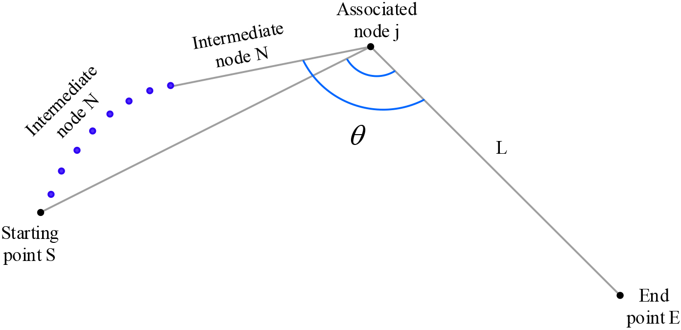
After determining the correct evaluation function, it is important to consider the performance of the algorithm. Most current algorithms input all the data into memory and then perform the minimum computation. In theory, the A* algorithm can find the fewest nodes in the shortest path. However, there are two issues to consider. First is the speed of reading and writing and second is the memory capacity of the system. When the system’s memory is large enough, the same nodes are looked up over and over again. This leads to a decrease in computing efficiency. To solve the problem of reading data, some scholars have proposed an A* algorithm based on a finite area to reduce the loading of data. However, since the A-algorithm itself has a certain loss, the research proposes a distance and angle-based normalisation method in order to solve the problems in the A* algorithm. That is, the corresponding distance and angle values of each relevant node in the current node are first found, and then their average values
In Eqs (8) and (9),
In Eq. (10),
Improved A* algorithm evaluation function cost.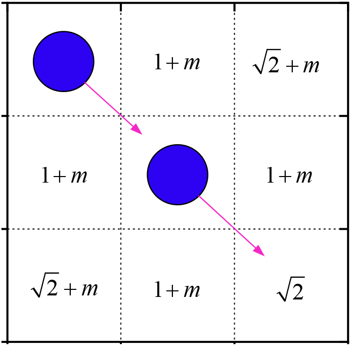
Improved A* algorithm flow chart.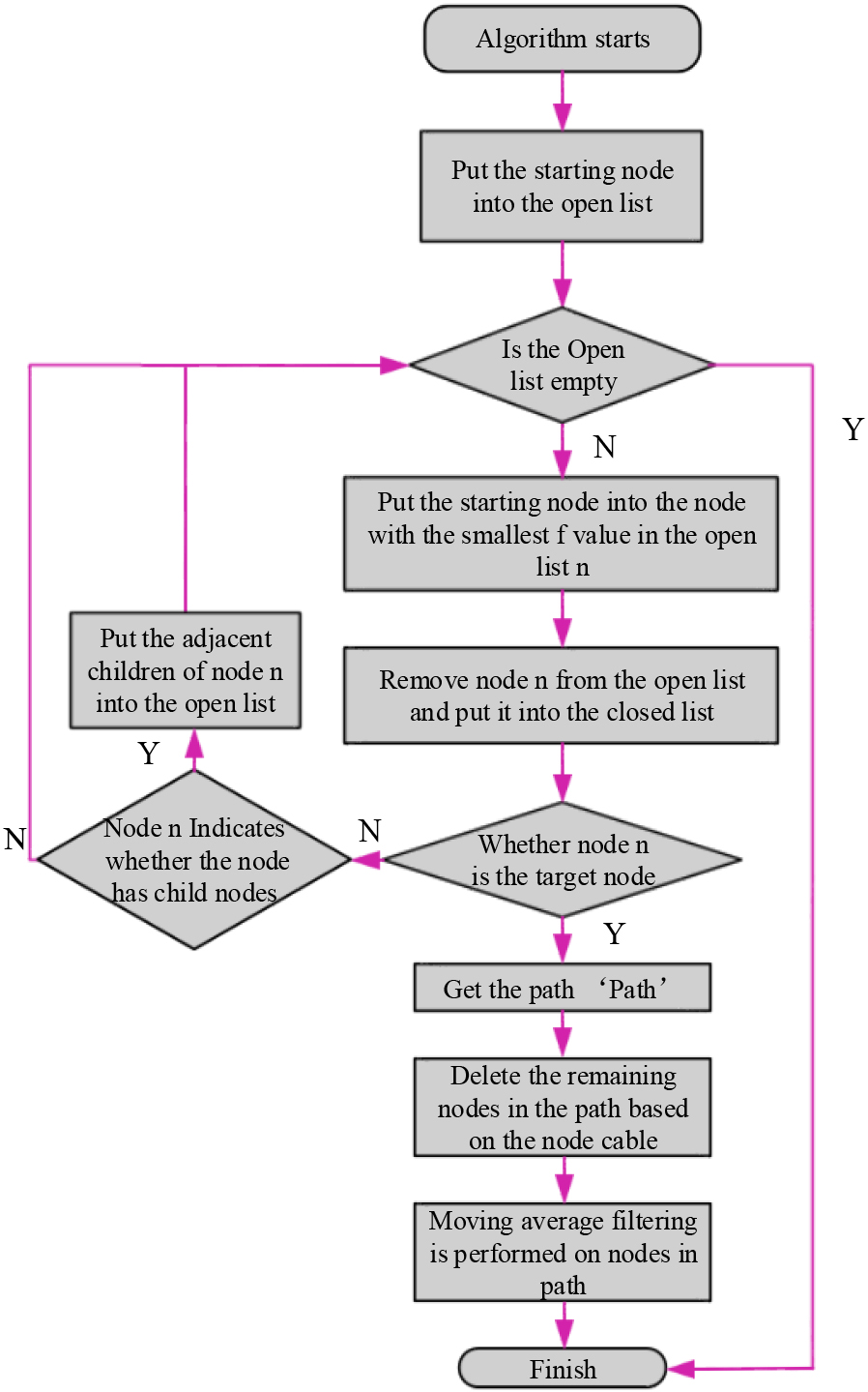
In Fig. 6, when the current node and the parent node move in the same direction, the evaluation function of the improved A* algorithm is used. The cost of nodes with the same moving direction in the grid graph is
As shown in Fig. 7, the algorithm operation steps are as follows. The first step is to initialize and generate the open list and closed list. The starting S information is put in the open list. The closed list is blank. The second step is to check the nodes adjacent to the starting point S. The nodes that can be moved or possibly reached in this node enter the open list. The third step is to set the start point S as its parent. It removes the parent node S from the open table and puts it in the closed list. If this node exists, the path has been successfully planned. If there is no such node, the path will continue. The fourth step is to select the node adjacent to the starting point S from the open table. The evaluation function
Verification and analysis of spacecraft collaborative control and path planning algorithms
Python has many libraries available for path planning, including NetworkX, Osmnx, RDPy and PyDijkstra. They can be used to deal with complex path planning problems and provide the optimal path according to user needs. The operating system is Windows10; the installed memory is 32.00 GB; the CPU is Inter Core i7-10700k; the GPU is RTX 3080 12G. First of all, the operation of the simulated spacecraft and various possible situations faced by the spacecraft are studied. This experimental environment can be used to test the path planning algorithm, and real data can be used to simulate the real situation of spacecraft, so as to better verify the path planning algorithm.
Variation curves of delay 
As shown in Fig. 8, in the digital simulation, the relationship between the state maintenance degree A
Algorithm training efficiency comparison chart.
From Fig. 9 that the improved A* algorithm has been analyzed through experiments, and the spacecraft has been used as the research object. The test results showed that the improved A* algorithm could significantly improve the path planning performance of spacecraft. The pink dotted line indicates the efficiency of applying the improved A* algorithm to spacecraft route planning; The blue dotted line indicates the efficiency of A* algorithm for spacecraft route planning. After 21 ms, the improved A* algorithm would reach the expected error, and its MAE value was 10 - 4. However, the A* algorithm took 100 ms and still failed to reach the expected error. Therefore, the improved A* algorithm proposed in this study was more efficient and less error for spacecraft route planning. Its running time and path planning quality have improved. The study also found that in complex environments, the improved A* algorithm could more effectively implement path planning and improve the safety of space vehicles. The results of this study provide a useful reference for the path planning of space vehicles. To sum up, the improved A* algorithm proposed in this study is more efficient and less error for spacecraft route planning. This shows that the improved algorithm proposed in the study has better actual effect.
After the verification of spacecraft cooperative control, the research selects 20 * 20 grid graphics for flight simulation. The black box represents obstacles; the blue circle indicates the starting position; the diamond represents the end position; the blank area represents the passable airspace. And through the optimization of the A* algorithm, path planning in flight aviation environments can better reflect self-adaptability, resulting in an increasing number of paths to choose from. The results of global route planning using A* and improved A* algorithms are shown in Fig. 10.
Comparison of flight path planning results of the vehicle before and after algorithm improvement.
Comparison of route planning for flight sections before and after algorithm improvement.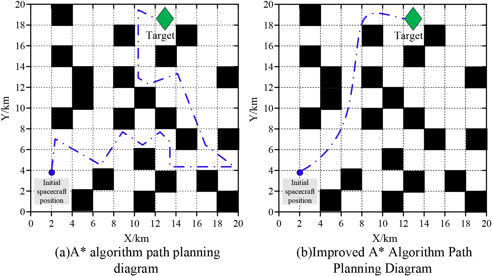
From Fig. 10, it is found that using the improved A* algorithm and A* algorithm to plan paths in the same environment can yield different results. Through comparison, we could find that the improved A* algorithm had better path selection than A* algorithm. A* algorithm was limited by the direction of motion in path planning. When avoiding obstacles, the turning points of A* algorithm were too many and too complex, which was not conducive to aircraft operation. The improved A* algorithm could adapt to the environment when planning the path and better met the operational requirements of aircraft. The smooth flow of the aircraft also lengthened the travel time. There was no good control over its energy consumption. Through the simulation experiment of the improved A* algorithm, the results show that this method had a significant improvement in node selection compared with A* algorithm. The number of inflection points, path smoothness and other performance indicators were significantly improved.
Figure 11 is a schematic diagram of the two algorithms for path planning in the air flight section environment. From the comparative experiment that the improved A* algorithm proposed in the study was significantly better than the previous A* algorithm. The improved A* algorithm was more scientific in its planning route. The inflection point was reduced a lot, and the path length was also significantly improved. In addition, the evaluation function of A* algorithm has been improved. When deleting redundant nodes, it could reduce the amount of computation and space. It has significantly improved the path security and enhanced the reliability of the system.
Table 1 shows the A* algorithm and the improved A* algorithm to carry out multiple sets of simulation experiments with different space structures. Under the same conditions of external factors, obstacle information, starting point and ending point of the test, the route planning test results of 8 regions were compared. On this basis, the path length, running time and node number of the two methods were compared. From the simulation test of A* algorithm and improved A* algorithm, when A* encounterd unknown obstacles, it could not pre-judge and plan the optimal path in advance, and the planned path was the minimum path. Its path had fewer turning points and was relatively stable. In the actual application of the route, the A* algorithm could be used because some locations were unknown. This could reduce path changes and improve the stability of the journey. The improved A* algorithm had more advantages in route planning. Because it could consider more factors, such as the minimum number of turns, the smoothness of the path, flight time, flight distance, etc. This can effectively meet the requirements of the actual application of the route, so that the flight can be safer and smoother.
Comparison of A* algorithm and improved A* algorithm
As a new multi-spacecraft cooperation mode, spacecraft cluster has become an important research topic in distributed space systems. Many key technologies of spacecraft cluster need to be simulated, analyzed and verified on the ground. In response to the above requirements, the research carried out the simulation effect analysis of spacecraft cooperative control and path planning, which showed that cooperative control can improve the control effect of spacecraft, shorten the time of path planning, and reduce the motion energy consumption of spacecraft. This provided an effective guarantee for the safe flight of spacecraft. The research results showed that after 21 ms, the improved A* algorithm reached the expected error, and its MAE value was 10 - 4. However, the A* algorithm took 100 ms and still failed to reach the expected error. The improved A* algorithm was more efficient and less error for spacecraft route planning, and then the spacecraft regulation and complex road sections were planned. It was found that the path selection of the improved A* algorithm was better than the A* algorithm. A* algorithm was limited by the direction of motion in path planning. When evading obstacles, its turning points were too many and too complex, which was not conducive to the precise control of spacecraft. The improved A* algorithm had fast path planning speed and high efficiency. The search area has also been greatly reduced, and the search efficiency has also been greatly improved. This shows that the improved A* algorithm proposed in this study has great improvement in path planning and can effectively improve the efficiency of path planning. However, there is a lack of systematic research on attitude control in collaborative control of spacecraft formation, as well as a lack of consideration for real-time communication issues in space formation missions. Therefore, further in-depth and improved research is needed in the future.
Footnotes
Funding
The research is supported by Natural Science Basic Research Project of Shaanxi Province of China (2023-JC-QN-0004); Provincial Training Program of Innovation and Entrepreneurship for Undergraduates (S202210719113).