
Abstract
The traditional numerical analysis method of deformation mechanics of bolt support has the problems of poor numerical simulation effect and accuracy. In this paper, the numerical simulation of deformation mechanics of bolt support in high stress mine roadway is studied. This paper analyzes the principle of bolt in high stress mine roadway, constructs the deformation concentration parameter model of bolt support in high stress mine roadway, and calculates the bearing capacity of bolt; The elastic deformation equation of bolt support in high stress mine roadway is obtained, the energy balance control of bolt support in high stress mine roadway is realized, and the numerical simulation of deformation mechanical characteristics of bolt support in roadway is realized. The experimental results show that when the impact time is 18 ms, the deformation force of the proposed method and the actual bolt support is 286 kn, which indicates that the proposed method can obtain the deformation force results of the bolt support, and the proposed method can accurately simulate the deformation mechanical characteristics of the bolt support.
Keywords
Introduction
China’s coal reserves are rich and complete, with proven reserves of over hundreds of millions of tons, ranking the third in the world [1]. Coal has always been the most important part supporting China’s economic development, providing China with a variety of energy sources [2]. In order to develop the national economy, China still needs to ensure high and stable coal yield in a long period of time [3]. The mining depth of China’s mines is increasing at an average rate of meters per year, and the eastern mines are developing at a rate of meters per year [4]. Taking Huainan mining area as an example, the mining depth of the mine has exceeded meters, and the first mining level of the newly built Guqiao and Dingji mines is more than thousands of meters. More than one coal resource in China is buried in more than meters, and the more complex the mine roadway is, the more and more it shows the characteristics of soft rock. Therefore, it is urgent to find a mining technology suitable for soft rock environment and the theory related to the deformation of bolt support in high stress mine roadway, so as to ensure the safe and efficient production of coal mine with scientific theory. For this reason, the related scholars have studied it and made some progress.
Liu et al. [5] based on bolt support role control technology of high stress soft rock tunnel excavation, USES fenner formula and Mohr strength theory to quantitative support strength, through core anchor supporting mechanism of roadway convergence monitoring, by using the theory of nonlinear coupling support roadway deformation mechanics analysis of three kinds of transformation process, can form a new type of rebar multilayer composite arch high pressure grouting bolt and the supporting method of tunnel reinforcement. This method can give full play to the role of bolt support, effectively control the roadway serious deformation, ensure the stability of the roadway, and reduce the cost of support. Wu et al. [6] such as deep mining loose and broken all coal roadway deformation characteristics and the reasonable supporting technology, according to the measured results of deep mining loose and broken the deformation characteristics of the whole and the two sides of roadway roof coal is analyzed, two sides roadway appears as significant plastic deformation instability in central and central loose coal roof and immediate roof structure surface produce unstable layer alienation. In order to ensure the stability of the roadway, the anchor rod is arranged in the middle of the two sides of the original trapezoidal shed roadway to control the plastic deformation in the middle of the roadway, the prestressed anchor cable is arranged in the middle of the roadway roof to ensure the stability of the loose top coal bed separation, and the conduit is arranged in the shallow part of the loose coal body within the range of 2.0–2.5 m to ensure the smooth construction of the anchor cable. Chen and Cui [7] studied the bolt support characteristics of typical shallow coal seam mining roadway, and adopted the method of combining numerical simulation with field measurement to discuss the bolt stress state and evolution rule at different positions of shallow buried thin bed coal seam mining roadway. The results show that although the design parameters of the bolt are the same, the mechanical characteristics of the same bolt will be significantly different as long as the position of the bolt is different.
In order to improve the numerical simulation effect and accuracy of bolt support deformation mechanics, aiming at the problems existing in the above methods, this paper makes a numerical simulation study on the deformation mechanical characteristics of bolt support in high stress mine roadway. By analyzing the principle of bolt support in high stress roadway, the deformation concentration parameter model of bolt support in high stress roadway is established, and the bearing capacity of bolt support is calculated; The elastic deformation equation of bolt support in high stress roadway is obtained, and the numerical simulation of deformation mechanical characteristics of bolt support in high stress roadway is completed, in order to provide some help for improving the effect and accuracy of numerical simulation of bolt support deformation mechanics.
Bolting and injection supporting mechanism
Principle analysis of high stress mine roadway bolt
Under the guidance of the anti-impact control concept of materials with constant resistance and large deformation, and inspired by the philosophical thought of “using softness to overcome firmness and combining hardness with softness”, scholars from the State Key Laboratory of Geomechanics and Deep Underground Engineering first proposed the concept of negative Poisson’s ratio structure and scientific problems of mechanical behavior in the field of rock mechanics at the macroscopic scale of 10-2-10 m, developed the bolt with negative Poisson’s ratio effect, and applied it to the control, monitoring and prediction of deep dynamic disasters and landslides [8]. On the premise of realizing large deformation and large elongation, the anchor bolt can absorb the deformation energy of surrounding rock to the maximum extent and keep the resistance basically stable [9]. The new supporting material is mainly composed of nut, tray, constant resistance bushing and rod body, as shown in Fig. 1. Among them, the constant resistance casing and the rod body jointly constitute the constant resistance device of the bolt, the constant resistance casing tail is equipped with a nut and a tray, and the nut and the constant resistance device are connected through threads.
Schematic diagram of anchor rod.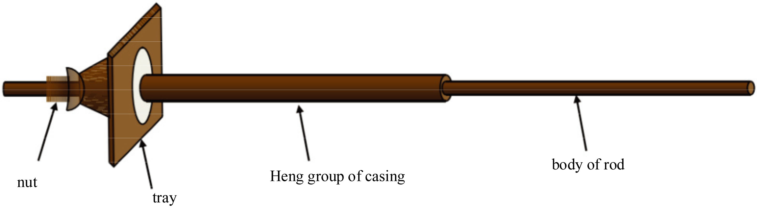
As can be seen from the Fig. 1, when the deep surrounding rock has creep or large deformation impact, the anchor bolt can automatically adjust and generate sliding deformation according to the impact energy, so as to resist the deformation of rock mass and keep the support force constant [10]. Therefore, the anchor bolt with constant resistance can rely on the frictional sliding deformation of the constant resistance body to absorb the impact energy of large deformation of surrounding rock and maintain constant support resistance to ensure the stability of the roadway [11]. The anchor bolt is a composite device with a unique negative Poisson’s ratio structure. Figure 2 is a schematic diagram of its structural composition principle.
Schematic diagram of anchor bolt.
According to Fig. 2, the bolt consists of a piston-like cone (installed in the casing), a rod (rebar) mounted on the cone, a casing (whose inner diameter is slightly larger than the diameter of the large end of the cone), a tray (used to transfer the deformation of the rock mass to the casing) and a fastening nut (force transmission device) [12]. When the axial external load (tension) acts on the free end of the bolt, the casing will produce a displacement in the opposite direction to the anchor end, which is the deformation of the bolt [13]. The motion of the casing corresponds to the slip of the cone relative to the casing wall. The smaller end of the cone is slightly smaller than the inside diameter of the casing, while the larger end is slightly larger than the inside diameter of the casing. When the cone slides in the casing, the radial expansion deformation of the casing will occur, resulting in negative Poisson’s ratio structure effect.
On the basis of bolt support and shotcrete support, brick masonry is adopted on the original metal support. According to the bearing capacity of the wall after grouting, the integrity of the support structure can be strengthened, the stability of the support structure can be guaranteed, and it has both elasticity and the pressure effect of bolt support. The combined support system can be formed by using the shotcrete support methods such as metal support and the rigid support function of brick and stone masonry, so as to jointly maintain the stability of the roadway [14]. Its supporting mechanism includes the following aspects:
The grouting bolt grouting can use the grout to block the cracks in the surrounding rock, isolate the air, prevent the weathering of the surrounding rock, and effectively prevent the surrounding rock from being soaked by water and reduce the strength of the surrounding rock itself.
After grouting, the loose and broken surrounding rock is cemented into a whole, which improves the cohesion, internal friction Angle and elastic modulus of the rock mass, thus improving the strength of the rock mass, and can realize the use of the surrounding rock itself as a part of the supporting structure [15].
After grouting, the backfill of the shotcrete layer wall is compacted, so as to ensure that the load can act on the shotcrete layer and support evenly, and avoid the occurrence of stress concentration points and damage in the first place.
A multi-layer effective composite arch can be formed by grouting the crack of surrounding rock with grouting bolt and shotcrete support, which expands the effective bearing range of the supporting structure and improves the integrity and bearing capacity of the supporting structure.
The composite arch thickness of shotcrete layer is composed of shotcrete layer (
In Eqs (1) and (2),
In general, the spacing between rows of bolts is equal, that is,
In Eq. (4), row spacing between bolts
Therefore, the thickness of composite arch formed by bolt-shotcrete support is:
After grouting support with grouting bolt, the composite arch thickness is:
In Eq. (7), the thickness of
After grouting, the pressure acting on the vault can be effectively transferred to the two walls, and through the reinforcement of the two walls, the load can be transferred to the floor. The increase of the thickness of the composite arch will reduce the load concentration of the floor and the stress in the floor rock, weaken the plastic deformation of the floor and reduce the shaking of the floor. The stability of the floor is conducive to the stability of the two walls. When the floor and the two walls are stable, the stability of the vault can be maintained. The stability of the roof is not only related to the load of the roof, but also related to the stability of the bottom plate and two side walls in the non-destructive area. Therefore, the key of bolt support technology is to ensure the stability of the bottom plate and two side walls, so as to ensure the overall stability of the support structure. In addition, the grouting bolt itself is a full-length bolt. The ordinary end bolt is transformed into a full-length bolt through grouting, so that the multi-layer composite arch can be combined into a whole and bear the load together, which can improve the integrity of the support structure. Grouting can increase the section size of the support structure and reduce the bending distance caused by the load of surrounding rock acting on the support structure, so as to reduce the tensile stress and compressive stress generated by the support structure. Therefore, it can bear greater load and improve the bearing capacity and adaptability of the support structure. Finally, under the action of grouting, the integrity of surrounding rock can be formed and maintained.
The elastic deformation equation of bolt support is obtained
The movement of the negative Poisson’s ratio structure in the bolt is a dynamic process, and the concentrated parameter model of the bolt is shown in Fig. 3.
Centralized parameter model of anchor bolt.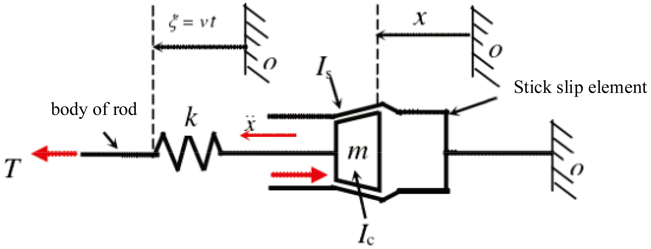
The motion equation of the centralized parameter model in Fig. 3 is:
In Eq. (8),
In Eq. (9),
The elastic deformation corresponding to the rod body:
Stick-slip motion corresponding to the anchor bolt:
Parameter
where, the equivalent friction coefficient of stick-slip movement is a frequency-dependent parameter:
In Eq. (14),
As can be seen from the figure, in the ideal elastic stage, when the external load is less than the constant resistance
The first term of Eq. (15):
Is the elastic energy absorbed by the elastic deformation of the material of the rod.
The second term of Eq. (15):
Is the energy absorbed by the large deformation of the anchor bolt at the yield stage of the structure.
The energy balance equation of roadway bolt support in high stress mine field can be written as:
In Eq. (19),
According to Eq. (19), the excess energy
Energy
Design of experimental scheme
In the impact tensile test system of roadway bolt support, each bar and sample are guided by a guide frame and supported by a fixed seat, which all meet the coaxial requirements of the initial state and motion state, and meet the one-dimensional assumption and the requirements of coaxial impact. In the experimental system, all the components are made of high-strength steel material, with little difference in strain rate, which meets the requirements of uniformity. The wave impedance of each component in the experimental system is shown in Table 1.
Basic parameters of experimental system materials
Basic parameters of experimental system materials
Compared with the traditional experimental method, because the design method can directly add the correction formula to the SigmaPlot analysis software of the data acquisition system component, the impact sensor can be directly used to extract the data from the analysis results, so the inertia effect caused by energy loss can be avoided to a great extent. The experiment only investigates the force and deformation dynamic characteristics of roadway bolt support, and does not excessively study the stress-strain relationship. Moreover, butter is applied to the contact parts of each component to lubricate them, so both the dispersion effect and friction effect can be ignored. When the roadway bolt support is subjected to impact, the constant resistance casing is bound to have radial deformation, so the investigation of the two-dimensional effect is also the focus of this paper.
In this experiment, the NPR bolts numbered mg-15-1, mg-15-4, mg-15-5 and mg-15-6 were used, with an average length of 1262 mm. The average diameters of the convex and concave parts of the external thread of the constant resistance casing were 32.48 mm and 29.45 mm, respectively. The average diameters of the convex and concave parts of the internal thread of the constant resistance casing were 28 mm and 25 mm, respectively. The convex wall of the external thread of the bolt was 4.48 mm, and the concave wall thickness of the external thread was 4.45 mm. The bolt parameters are shown in Table 2.
Basic physical parameters of single experimental bolt sample
When a single bolt is impacted for a single time, firstly, the screw tightening degree of each working component should be checked to ensure the stability during impact. Secondly, the system and sensors should be cleared, and the air source strength of the loading system should be set for loading. After the single impact, the velocity, force and displacement were measured.
Expansion of bolt support sample in high stress mine roadway
The expansion relationship of four groups of single anchor bolt impact tensile test bolt is shown in Table 3.
Relation table of bolt sample expansion
Relation table of bolt sample expansion
It can be seen from Table 3 that the average diameter of the external thread protrusion of the four groups of samples before the experiment is about 32.48 mm, and the average diameter of the external thread protrusion of the four groups of samples after the experiment is about 33.11 mm. Since the constant resistance body does not contact the convex part of the internal thread during impact, it is assumed that the average diameter of the convex part of the internal thread remains unchanged and is still 28 mm (the diameter of the rod body is 22 mm). After the experiment, the average wall thickness of the convex part of the screw thread is about 5.11 mm (the initial average is 4.48 mm, the wall thickness increases by 0.63 mm), and the expansion of the wall thickness of the convex part of the external screw thread is about 0.63 mm (the wall thickness becomes thicker, the whole expansion); Before the experiment, the average diameter of the concave part of the external thread of the four groups of samples is about 29.45 mm, and after the experiment, the average diameter of the concave part of the external thread of the four groups of samples is about 31.03 mm. Since the constant resistance body contacts and extrudes the convex part of the internal thread to make its diameter equal to the diameter of the constant resistance body by 28 mm, it is assumed that the average diameter of the concave part of the internal thread becomes 28 mm after the experiment. After the experiment, the average wall thickness of the screw recess is about 3.03 mm (the initial average is 4.45 mm, the wall thickness increases by 1.42 mm), and the expansion of the wall thickness of the external screw recess is about 1.58 mm (the wall thickness becomes thinner, but the whole body expands).
The above experimental data show that the convex and concave parts of roadway bolt support expand and coarsen under the impact force. Because of the different contact and force action of the constant resistance body in the constant resistance casing (the constant resistance body directly contacts the concave part of the internal thread but does not contact the convex part of the internal thread), the increase of the wall thickness of the convex part of the internal thread is equal to the expansion amount, and although the wall thickness of the concave part of the internal thread becomes thinner, it still shows the expansion phenomenon.
In order to verify the elongation change of bolt support sample in high stress mine roadway, four groups of bolt support parameters before and after the experiment are obtained in Table 4.
Relation table of bolt sample elongation
Relation table of bolt sample elongation
It can be seen from Table 4 that the average length of four groups of samples in mg-15-x batch is 1262 mm, the average length of constant resistance device is 514.75 mm, and the average length of constant resistance casing is 450 mm; After the experiment, the average elongation of four groups of bolt samples is 450.5 mm, and the average elongation is 35.70%. The above experimental data show that the macro performance of roadway bolt support under the impact force is the relative displacement of the rod body and the constant resistance casing, that is, the constant resistance device tensile elongation. When a certain number of impact times is reached, the rod body rushes out from the constant resistance casing, and the length of the rod body is the final bolt elongation.
After the single bolt impact tensile test, read the bolt data after a single impact in the test and analysis software and store it in TXT format. Paste the data into Excel software and draw the impact force time curve by sigma plot software. Figure 4 is the bolt support force time curve drawn under the impact in this experiment.
Stress change of bolt support under different methods.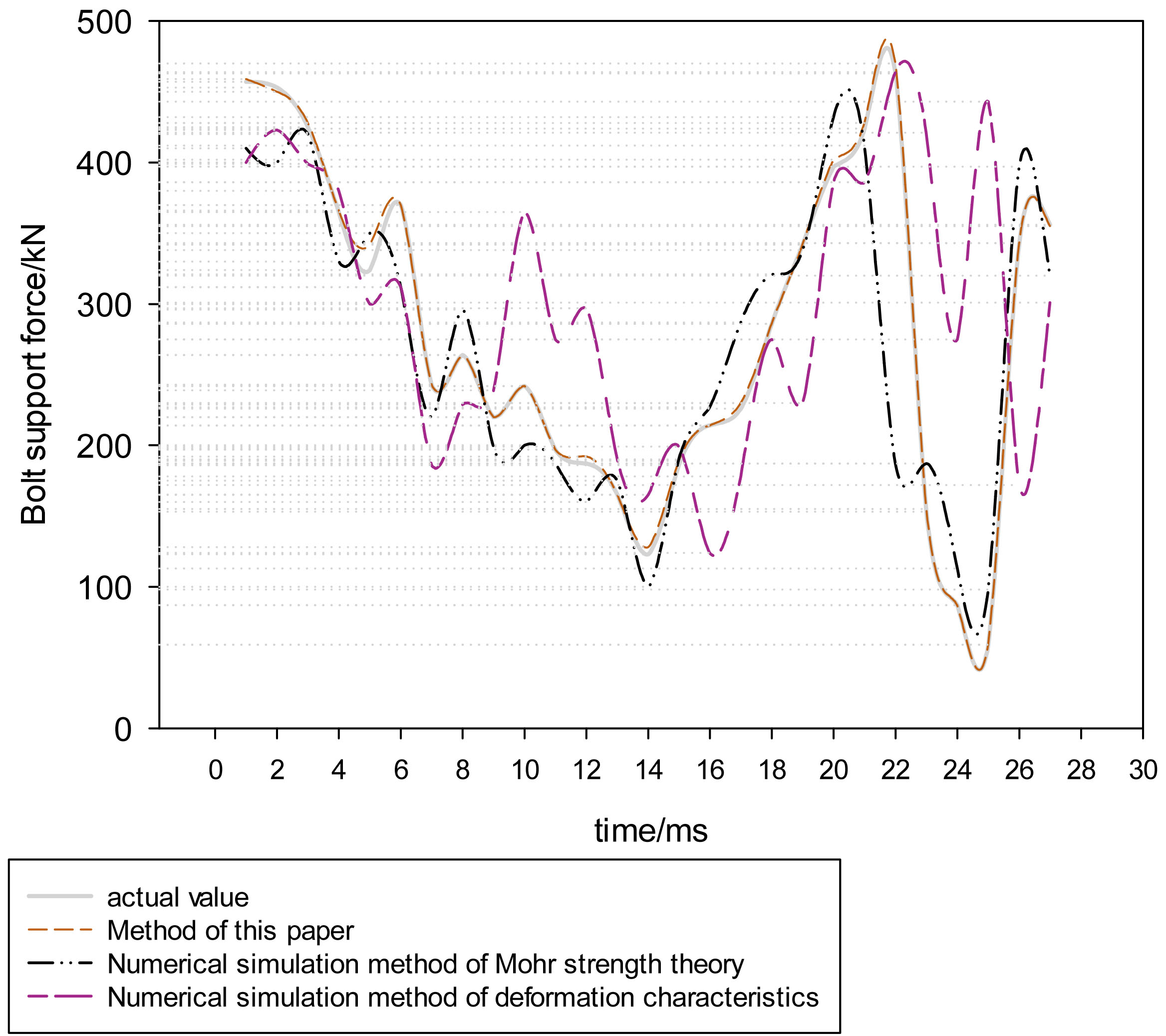
According to the analysis in Fig. 4, when the impact time is 7 ms, the bolt support deformation force of the numerical simulation method of Mohr strength theory (method in Reference [10]) is 220 kn, the bolt support deformation force of the numerical simulation method of deformation characteristics (method in Reference [9]) is 186 kn, the bolt support deformation force of this method is 243 kn, and the actual value of bolt support deformation force is 243 kn. When the impact time is 18 ms, the bolt supporting force of Mohr strength theory numerical simulation method is 321 kn, the bolt supporting deformation force of deformation characteristics numerical simulation method is 275 kn, the bolt supporting deformation force of this method is 286 kn, and the actual value of bolt supporting deformation force is 286 kn. It can be seen that the accuracy of the support stress values obtained by other methods is poor, and the deformation stress values obtained by this method are basically consistent with the actual values, which indicates that this method can obtain the deformation stress results of bolt support. This is because the design method in this paper analyzes the principle of bolt support in high stress roadway, establishes the concentrated parameter model of bolt support deformation in high stress roadway, and calculates the bearing capacity of bolt support; The elastic deformation equation of bolt support in high stress roadway is obtained, and the numerical simulation of the deformation mechanical characteristics of bolt support in high stress roadway is completed, which ensures the numerical simulation effect from many aspects, so the effect is better.
In this paper, a numerical simulation method of deformation mechanical characteristics of bolt support in high stress roadway is proposed, a concentrated parameter model of bolt support deformation in high stress roadway is established, and the bearing capacity of bolt support is calculated; The elastic deformation equation of bolt support in high stress roadway is designed, and the numerical simulation of deformation mechanical characteristics of bolt support is realized. The results are as follows:
After the bolt support of roadway is impacted by the impact force, it shows that both the convex part and the concave part expand and coarsen macroscopically. Because of the different contact and force action of the constant resistance body in the constant resistance casing, the increase of the wall thickness of the convex part of the thread is equal to the expansion, while the wall thickness of the concave part of the thread is thinner, but it still shows the expansion phenomenon. After the roadway bolt support is impacted, the macro performance is the relative displacement of the rod body and the constant resistance casing, that is, the constant resistance device is stretched. When a certain number of impact times is reached, the rod body rushes out from the constant resistance casing, and the length of the rod body is the final bolt elongation. When the impact time is 18 ms, the deformation force of this method and the actual bolt support is 286 kn, which shows that this method can accurately obtain the deformation force of bolt support.