
Abstract
In wireless networks, the handover in the network layer (L3) is usually initiated after the handover in the link layer (L2) is complete, so the total handover delay is equal to the sum of the L2 handover delay and the L3 handover delay. In order to reduce the total handover delay, this paper studies the correlations between the L2 messages and L3 ones, and proposes a cross-layering handover scheme. The main idea behind this scheme is to effectively combine the related messages in L2 and L3 and achieve the L3 handover with the L2 messages in order to minimize the effect of the L3 handover delay on the total handover delay. The performance of this scheme is evaluated, and the results show that this scheme effectively reduces the total handover delay.
Introduction
IEEE 802.16-based worldwide interoperability for microwave access (WiMAX) and long term evolution (LTE) standards are two promising technology forerunners for the wireless scenario [4,13,15]. Especially, IEEE 802.16 [6] proposes the mobility support for the next-generation wireless access system. Since this paper focuses on the mobility handover issue for the next-generation access system, we propose a cross-layering handover scheme for the IEEE 802.16-based access system and aim to reduce the total handover delay.
In wireless networks, the handover in network layer (L3) is initiated after the one in the link layer (L2) is complete. As a result, the total handover delay is equal to the sum of the L2 handover delay and the L3 handover delay [19,21]. The L2 handover happens when a mobile station (MS) changes its point of attachment. During the L2 handover, an MS disconnects with the serving base station (BS) and establishes the connection with the new BS. The L3 handover occurs when two BSs involved in the L2 handover are located in different IP subnets. In this case, the network prefix changes, so an MS needs to acquire a new care-of address (CoA) to ensure communication correctness. Usually, the L3 handover process is made up of three parts [10]: movement detection, CoA configuration, and address binding. Among them, CoA configuration is the most time-consuming process [2]. In order to reduce the L3 handover delay, fast handover for mobile IPv6 (FMIPv6) [10] is proposed and aim to minimize the delay caused by CoA configuration.
Since the total handover delay is the sum of the L2 handover delay and the L3 handover delay, the cross-layering designs are proposed to reduce the handover delay [5]. However, most of the cross-layering designs merely overlay the L2 and L3 handover procedures without taking into account the correlations between the L2 messages and L3 ones, so the total handover delay improvement is limited [12].
The main idea behind this scheme is to effectively combine the related messages in L2 and L3 and achieve the L3 handover with the L2 messages in order to minimize the effect of the L3 handover delay on the total handover delay. This paper has the following contributions:
The message sequences in IEEE 802.16 and FMIPv6 are analyzed, and the correlations between these messages are studied. Based on these correlations, the related messages in L2 and L3 are effectively combined.
Based on these correlations, the L2 messages are employed to help achieve the L3 handover including the movement detection, the CoA configuration and the address binding. Moreover, the CoA uniqueness can be guaranteed without DAD.
The L2 and L3 handovers are performed in parallel.
This paper is organized as follows. In Section 2, the related work on mobility support in wireless networks is discussed, in Section 3 the L2 and L3 handovers are analyzed, and in Section 4 the cross-layering scheme is presented. The performance of this scheme is evaluated in Section 5, and this paper concludes with a summary in Section 6.
Related work
In order to effectively reduce the total handover delay, cross-layering designs are proposed to perform the handover because they can serve well for wireless networks and achieve good performance [5].
Based on this cross-layering design idea, the standard [8] integrates the L2 and L3 handover procedures to improve the handover performance. However, this standard only overlays the L2 and L3 handover procedures. In [3], the authors propose a cross-layer handover approach based on context awareness to reduce the handover latency. In this approach, a pre-registration mechanism is presented to reduce the register latency, and moreover the media independent handover is utilized to reduce the handover latency. In [11], a call admission control algorithm is proposed to deal with handovers and aim to improve the handover successful rates and reduce the handover latency. In [9], a fast handover solution for wireless networks is proposed. This solution utilizes the media independent handover to reduce the handover latency. In [17], a handover decision mechanism based on WiMAX is proposed to reduce the handover latency and improve the handover efficiency in order to ensure communication continuity during the mobility process. In [20] a fast cross-layer handover scheme is proposed. In this scheme, the L2 and L3 handover mechanisms cooperate to shorten the handover latency. This scheme depends on the forwarding tables to achieve the communication. However, a forwarding table needs to maintain a list of all terminals in a domain, so the scalability is limited. Moreover, this scheme does not address the CoA configuration issue. In [14], the authors propose a cross-layer trigger-based handover scheme and aim to reduce the handover latency. This scheme makes use of the interactions between L2 and L3 handover procedures to perform the L2 and L3 handover in parallel.
The solutions above reduce the handover delay to some extent. However, these solutions do not take advantage of the correlations between the L2 messages and L3 ones to reduce the total handover delay, so the handover delay improvement is limited. This paper proposes a cross-layering handover scheme and aims to reduce the total handover latency by combining the related messages in L2 and L3 and achieving the L3 handover with the L2 messages.
In the IPv4 handover, CoA is the termination point of a tunnel toward a mobile node away from the home subnet and it is usually an address of a foreign agent (FA) with which the mobile node registers [16]. In the IPv6 handover, CoA is a unicast routable address associated with a mobile node when the mobile node is located in a foreign subnet [10]. Therefore, the IPv4 handover does not deal with the CoA configuration issue. However, this issue is an important part of the IPv6 handover because IPv6 does not have FAs anymore. Therefore, the proposed scheme also addresses the CoA configuration issue.
Handover in L2 and L3
Architecture
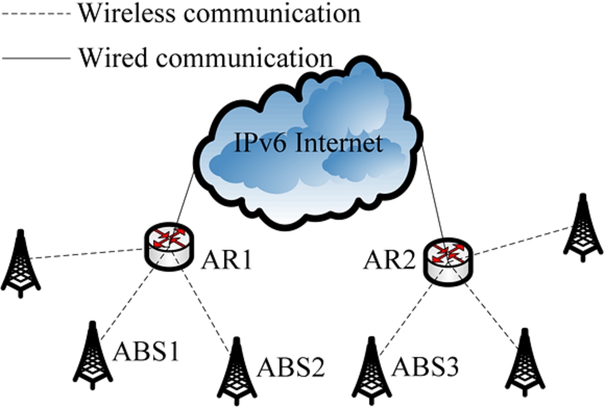
If an advanced MS (AMS) moves between two advanced base stations (ABSs) which are connected to an access router (AR), for example, ABS1 and ABS2 in Fig. 1, its IP address keeps unchanged. In this situation, the AMS only performs the L2 handover. If an AMS moves between two ABSs which link with different ARs, for example, ABS2 and ABS3 in Fig. 1, it needs to be configured with a new IP address to ensure communication correctness. In this case, the AMS perform both the L2 handover and L3 one.
Architecture.
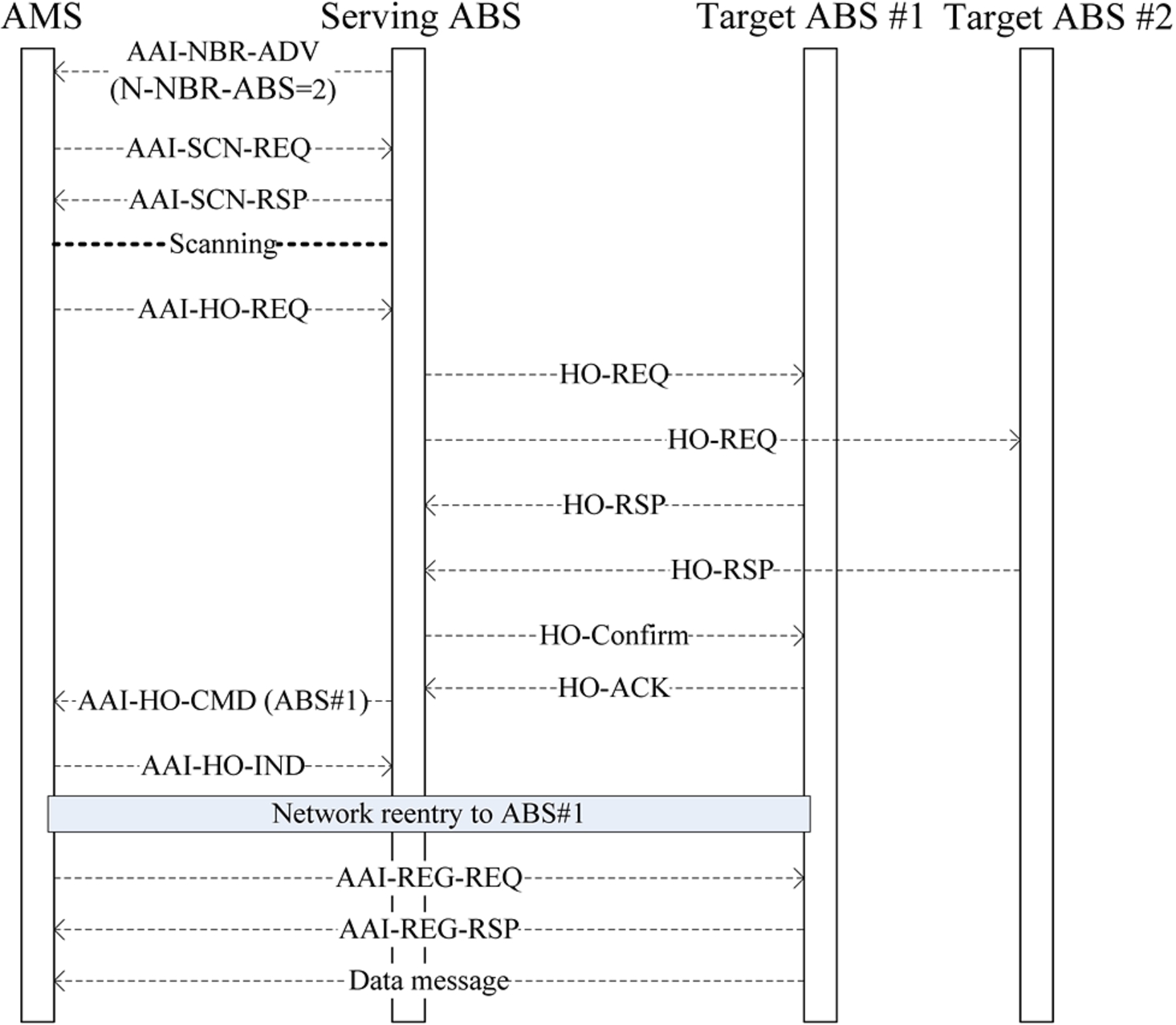
As shown in Fig. 2, the handover process in IEEE 802.16 is described as follows:
A serving ABS (sABS) regularly sends an AAI-NBR-ADV message which includes the channel information on the neighbor ABSs. After an AMS receives an AAI-NBR-ADV message from the sABS, it performs a scanning operation via exchanging AAI-SCN-REQ and AAI-SCN-RSP messages to check the suitability of the neighbor ABSs.
After an AMS chooses the target ABS (tABS) candidates, it sends an AAI-HO-REQ message to the sABS to initiate a handover.
The sABS determines whether these target ABSs can satisfy QoS requirements of the AMS by exchanging HO-REQ and HO-RSP messages with these candidates. Then, the sABS selects the best tABS and sends an HO-Confirm message to the best tABS which returns an HO-ACK message to acknowledge the receipt of HO-Confirm.
The sABS sends the AMS an AAI-HO-CMD message which includes the information on the best tABS.
The AMS sends the sABS an AAI-HO-IND message for the final handover execution which results in the network reentry process.
Finally, the AMS registers with the best tABS via exchanging AAI-REG-REQ and AAI-REG-RSP messages. In this way, the best tABS becomes the sABS of the AMS and begins to serve the AMS.
In Fig. 2, an AMS chooses two tABS candidates tABS1 and tABS2, and then the sABS selects tABS1 as the best tABS. Finally, the AMS registers with tABS1, and tABS1 becomes the sABS of the AMS and begins to serve the AMS.
Handover in L2.
Fast handover in L3.
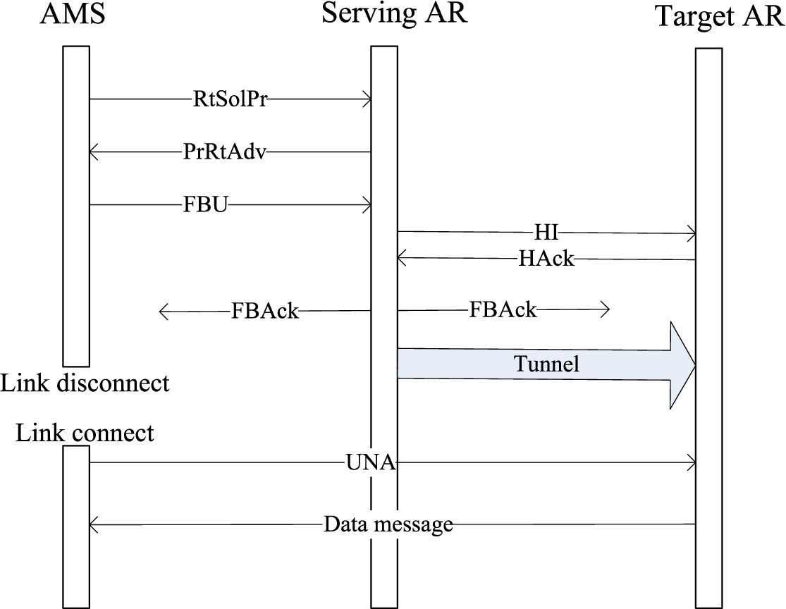
As shown in Fig. 3, the handover process in FMIPv6 is described as follows:
An AMS first acquires the information on the neighboring links including the new network prefixes to facilitate movement detection via exchanging a router solicitation for a proxy advertisement (RtSolPr) message and a proxy router advertisement (PrRtAdv) message. The AMS uses the new network prefix to be configured with a new CoA, and then sends a fast binding update (FBU) message to notify the serving AR (sAR) of performing a binding between the serving CoA and the new CoA. After the sAR receives this FBU message, it checks the uniqueness of the new CoA by exchanging a handover initiate (HI) message and a handover acknowledge (HAck) with the target AR (tAR). If the new CoA is not unique, the tAR assigns a unique CoA which is encapsulated in an HAck message. Then, the sAR performs a binding between the serving CoA and the new CoA. The sAR returns the AMS a fast binding acknowledgment (FBAck) message to acknowledge the receipt of FBU. If the tAR assigns a unique CoA to the AMS, then FBAck is also used to notify the AMS of the unique CoA. The AMS sends an unsolicited neighbor advertisement (UNA) message after it attaches to the tAR. Then, the tAR begins to forward the buffered data messages to the AMS.
Cross-layering handover
Overview
This section analyzes the L2 and L3 handover functions and tries to build the connections between them. The advantages of connecting L2 handover functions with L3 ones are two-fold:
Build the correlations between the L2 messages and L3 messages in order to employ the L2 messages to help achieve the L3 handover and minimize the effect of the L3 handover delay on the total handover delay.
Perform the L2 and L3 handovers in parallel in order to further reduce the total handover latency.
From Fig. 3, it can be seen that the L3 handover consists of the following three processes [10]:
Movement detection.
New CoA configuration.
Address binding.
These three processes are analyzed so that the L2 messages can be used to trigger these three processes:
In the L3 handover, RtSolPr and PrRtAdv are used to achieve the movement detection. In the L2 handover, AAI-NBR-ADV, AAI-SCN-REQ, AAI-SCN-RSP, AAI-HO-REQ, HO-REQ, HO-RSP and HO-Confirm are used to perform the movement detection. Therefore, RtSolPr and PrRtAdv can be replaced with AAI-NBR-ADV, AAI-SCN-REQ, AAI-SCN-RSP, AAI-HO-REQ, HO-REQ, HO-RSP and HO-Confirm to perform the movement detection. In the L3 handover, an AMS uses RtSolPr and PrRtAdv to acquire the new network prefix to construct a CoA. Then, FBU, HI and HAck are utilized to perform DAD to ensure the CoA uniqueness. In the L2 handover, HO-REQ and HO-RSP are used to select the best tABS which can satisfy the QoS requirements. Therefore, the tABS might use HO-REQ and HO-RSP to trigger the tAR to directly assign a unique address to an AMS in order to reduce the addressing delay. In the L3 handover, FBU and FBAck are used to perform the address binding. If the tAR assigns a unique address to an AMS, then FBAck is also used to notify the AMS of the assigned address. In the L2 handover, HO-Confirm and HO-ACK are used to confirm the best tABS. Based on the analysis in 2), HO-Confirm and HO-ACK might be used to confirm the assigned address and trigger the sAR to perform the address binding, and at the same time AAI-HO-CMD might be used to notify the AMS of the assigned address. In the L3 handover, UNA is used to notify the tAR of transmitting data. At this point, the L3 handover is complete. In the L2 handover, an AMS uses AAI-REG-REQ and AAI-REG-RSP to register with the tABS. Therefore, AAI-REG-RSP might be used to notify the tAR of transmitting data.
Design
In this scheme, the 1-bit parameter N is added in HO-REQ, HO-RSP, HO-Confirm, HO-ACK, AAI-HO-CMD, AAI-REG-REQ and AAI-REG-RSP. When N is equal to 1, it means that a message should be submitted to L3. In HO-RSP, HO-Confirm, HO-ACK, AAI-HO-CMD, AAI-REG-REQ and AAI-REG-RSP, when N is equal to 1, the 128-bit parameter NCoA is added and its value is the new address assigned by the tAR.
Based on the analysis in Section 4.1, the following cross-layering handover algorithm is proposed:
The sABS regularly transmits AAI-NBR-ADV. After an AMS receives AAI-NBR-ADV from the sABS, it performs a scanning operation via exchanging AAI-SCN-REQ and AAI-SCN-RSP to check the suitability of the neighbor ABSs.
After the AMS chooses the tABS candidates, it sends the sABS AAI-HO-REQ to initiate the handover.
After the sABS receives AAI-HO-REQ, it sends each tABS candidate HO-REQ where N is set to 1. After the tABS candidate receives HO-REQ, it forwards the HO-REQ to the tAR. Then, the tAR performs New-CoA-Conf where the output parameter is the assigned address. After the tABS candidate receives HO-RSP returned by the tAR, it forwards this message to the sABS.
New-CoA-Conf (New CoA)
Sender: L2 layer
Receiver: L3 layer
Execution: Assign a unique IPv6 address, mark this address as pre-configured state, and send tABS HO-RSP where N is set to 1
After the sABS receives HO-RSP returned by all the tABS candidates, it selects the tABS candidate tABS1 as the best tABS. Then, the sABS sends the sAR and tABS1 HO-confirm where N is set to 1 and NCoA is set to the assigned address. The sABS also sends the AMS AAI-HO-CMD where N is set to 1 and NCoA is set to the assigned address.
After tABS1 receives HO-confirm, it forwards this message to the tAR tAR1 which links with tBS1. After tAR1 receives HO-confirm, it performs New-CoA-Confirmation where the input parameter is the assigned address, and then returns HO-ACK to tABS1. tABS1 forwards this HO-ACK to the sABS to acknowledge the completion of the new CoA confirmation. After the sAR receives HO-confirm, it performs New-CoA-Binding where the input parameter is the assigned address and then returns the sABS HO-ACK to acknowledge the completion of the new CoA binding. Since the AR tAR2 does not receive HO-confirm with the assigned address, it changes the pre-configuration state of the assigned address into the idle state. After the AMS receives AAI-HO-CMD, it performs New-CoA-Acquisition where the input parameter is the assigned address.
New-CoA-Confirmation (New CoA)
Sender: L2 layer Receiver: L3 layer Execution: Change the pre-configuration state of the new CoA to the configured state Sender: L2 layer Receiver: L3 layer Execution: Perform the binding between the serving CoA and the new CoA
New-CoA-Binding (New CoA)
New-CoA-Acquisition (New CoA)
Sender: L2 layer
Receiver: L3 layer
Execution: Acquire and store the new CoA
The AMS sends the sABS AAI-HO-IND for the final handover execution which results in the network reentry process.
The AMS sends tABS1 AAI-REG-REQ where N is set to 1 and NCoA is set to the assigned address. After tABS1 receives AAI-REG-REQ, it sends the AMS AAI-REG-RSP where N is set to 0, and tAR1 AAI-REG-RSP where N is set to 1 and NCoA is set to the assigned address. After the AMS receives AAI-REG-RSP, it begins to wait for data. After tAR1 receives AAI-REG-RSP, it performs Handover-Termination where the input parameter is the new CoA.
Handover-Termination (New CoA)
Sender: L2 layer
Receiver: L3 layer
Execution: Send the buffered data to the AMS identified by the new CoA.
The handover process is complete, as shown in Fig. 4.
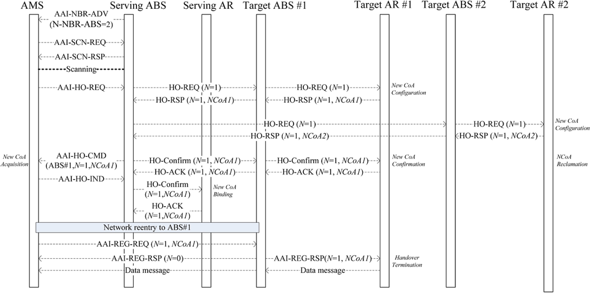
Cross-layering handover.
In this scheme, when the tAR receives HO-REQ, it performs New-CoA-Conf to assign an address to the AMS and marks this address as a pre-configured state. Only after the tAR receives HO-Confirm, it executes New-CoA-Confirmation and sends the sABS HO-ACK to confirm the completion of the address configuration. If the link fails before the tAR receives HO-Confirm, then the tAR reclaims the address in the pre-configured state (namely, changing the pre-configuration state of the assigned address into the idle state). If the link fails after the tAR performs New-CoA-Confirmation, then the sABS cannot receive HO-ACK. In this situation, the sABS resends HO-Confirm. If the sABS fails to receive HO-ACK from the tAR several times, it selects a new tABS. In this case, the tAR can reclaim the address assigned to the AMS in the following two ways:
When the tAR assigns an address to the AMS, it sets the lifetime of this address. If during the lifetime this address does not be renewed, then the tAR reclaims this address.
The tABS can notify the tAR of reclaiming the address assigned to the AMS when it detects that the AMS does not actually switch to it.
If the tAR assigns an address to the AMS before the network entry or registration is performed, then the AMS stores two CoAs, namely the original CoA and new CoA. In this case, the AMS receives data in the following two ways:
If the address binding is not executed, then the AMS still uses the original CoA to receive data from the sABS.
If the address binding is completed, then the data destined for the AMS first reaches the tAR which then forwards the data to the tABS. If the tABS detects that the AMS does not switch to it, then it temporarily buffers these data. After the AMS switches to the tABS, the tABS forwards these data to the AMS.
In the first way, the AMS still uses the original CoA to receive the data, so these data first reaches the sABS instead of tABS. Consequently, even if a malicious node spoofs the new CoA of the AMS, it is unable to intercept the data destined for the AMS. In the second way, only after the tABS detects that the AMS switches to it, it forwards these data to the AMS. Similarly, even if a malicious node masquerades as the AMS before the AMS switches to the tABS, it is unable to obtain the data destined for the AMS.
In Fig. 4, tAR1 assigns a new CoA NCoA1 to the AMS, and tAR2 allocates a new CoA NCoA2 to the AMS. Then, the AMS selects tABS1 as the best tABS, and acquires the new CoA NCoA1. After the cross-layering handover process is complete, the AMS begins to receive data from tABS1.
The tBS and tAR are separated or integrated together. In either case, the L3 module does not need to understand the L2 messages:
The tBS and tAR are integrated together
In this case, the tABS deals with the L2 messages. If the parameter N is 1, then the tABS directly triggers the tAR to perform New-CoA-Conf.
The tBS and tAR are separated
From the perspective of the protocol stack, the protocol stack in the tAR also includes the link layer although the tAR is an L3 device. If the tAR receives the L2 messages from the tBS, the L2 module in the tAR deals with these messages. If the parameter N is 1, then the L2 module triggers the L3 module to perform New-CoA-Conf to achieve the CoA configuration.
As shown in Fig. 4, this scheme employs the L2 messages to trigger the L3 module to perform the L3 handover and aims to minimize the effect of the L3 handover delay on the total handover delay. That is to say, just like in the layered networks, it is still the L3 module in this scheme that performs the actual L3 handover operations such as the CoA configuration and address binding, and the L2 module is not involved in these L3 operations. Therefore, the L2 and L3 are still independent of each other and the advantages of the layered networks still exist.
Ping-pong effects happen when a mobile node moves back and forth between two ARs. In this scheme, if an AMS moves between two ABSs which link with different ARs, ping-pong effects happen. Ping-pong effects may result in frequent handovers and cause a lot of message overheads.
In order to avoid frequent handovers caused by Ping-pong effects, in this scheme an ABS stores a handover table where each entry includes four fields: the AMS field, the previous ABS (pABS) field, the next ABS (nABS) field, and the lifetime field. Among them, the value in the AMS field is the link address of an AMS, the value in the pABS field is the ABS ID of the previous sABS of the AMS, and the value in the nABS field is the ABS ID of the tABS of the AMS. When an AMS selects the best tABS, the sABS creates a handover entry for the AMS to record the tABS of the AMS. If an AMS switches to the tABS, the tABS creates an entry for the AMS to store the pABS of the AMS. For example, in Fig. 4, after the sABS selects tABS1 as the best tABS, it creates a handover entry for the AMS where the nABS value is the ABS ID of tABS1. After the AMS switches to tABS1, tABS1 creates a handover entry for the AMS where the pABS value is the ABS ID of the sABS.
If the AMS switches back to the original sABS after it switches to the tABS, then the original sABS can determine that the AMS is performing the ping-pong movement by checking the handover entry for the AMS, namely moving back and forth between the tABS and itself. In this situation, the original sABS does not perform the L3 handover, so there are not message exchanges between the original sAR and tAR. Similarly, if the AMS switches back to the tABS after switching to the original sABS, then the tABS can determine that the AMS is performing the ping-pong movement by checking the handover entry for the AMS. In this situation, the tABS does not perform the L3 handover, so there are not message exchanges between the tAR and original sAR.
When the tABS detects that the AMS switches back to the original sABS, it can determine that the AMS is performing the ping-pong movement by checking its handover table. In this situation, after the tABS receives the messages destined for the AMS from the tAR, it uses the tunnel technology to send these messages to the original sABS. After the original sABS receives these messages, it forwards these messages to the AMS.
Performance evaluation
Based on Fig. 4, the time sequence diagram of this scheme is shown in Fig. 5 where the notations are shown in Table 1.
Parameters
Parameters
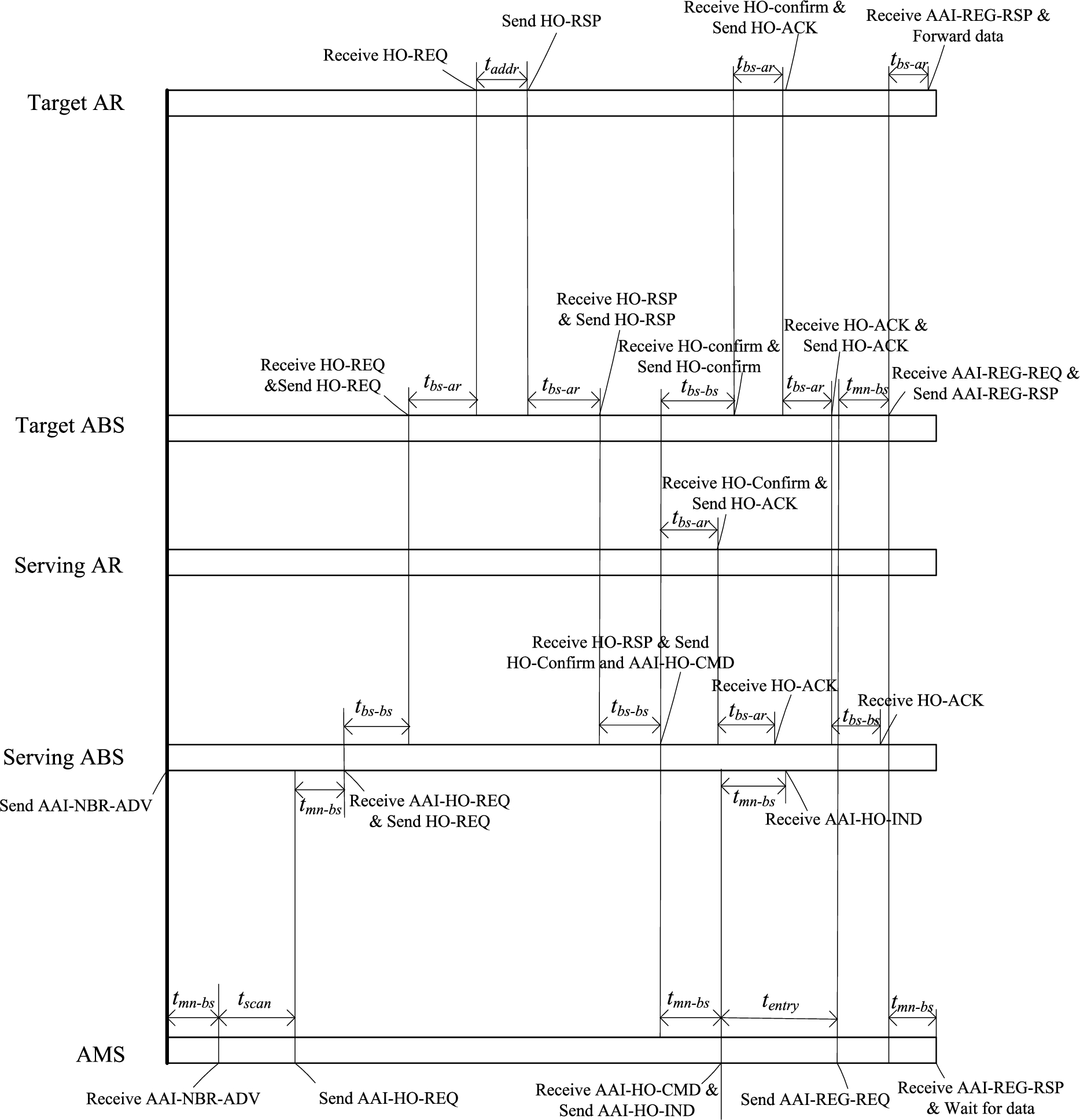
Time sequence diagram.
Based on Fig. 5, the handover delay T in this scheme is made up of the movement detection delay
The proposed scheme is compared with FMIPv6 and IEEE 802.16 which are performed in the standard way [8]. Based on Fig. 2 and Fig. 3, the handover delay
Network Simulator version 2 (NS-2) is used to evaluate this scheme, and the simulation parameters are shown in Table 2. In the simulation, the mobility pattern is random waypoint [7], and the user distribution adopts the random distribution [1,18].
Simulation parameters
When
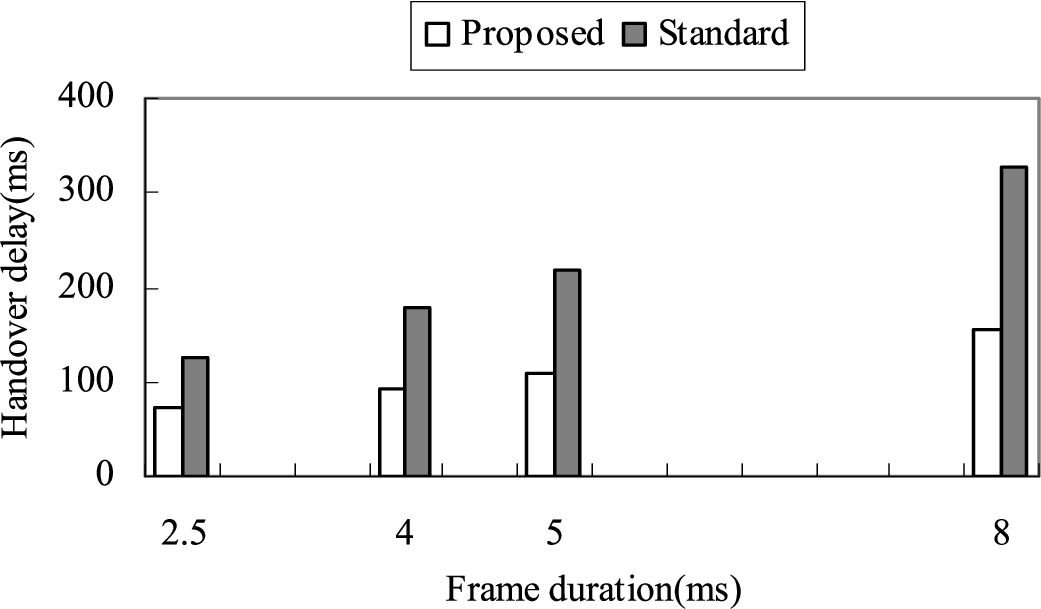
Handover delay based on frame duration.
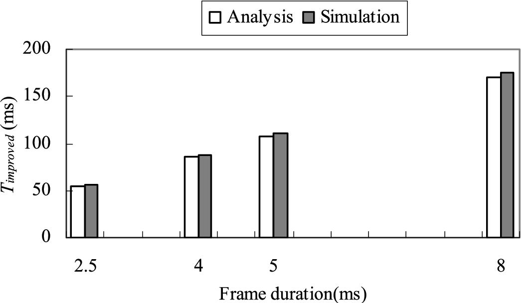
Handover delay improvement based on frame duration.
As shown in Fig. 6, the handover delays in both this scheme and the standard grow with the increase in frame duration, and this scheme has a lower handover delay than the standard. As shown in Figs 6 and 7, compared with the standard, the delay improvement grows with the increase in frame duration. The handover delay is reduced by 43%, 48.5%, 49.5% and 52% respectively when the frame duration is set to 2.5 ms, 4 ms, 5 ms and 8 ms. The main reasons are two-fold:
This scheme employs the L2 messages to help achieve the movement detection, CoA configuration and address binding in the L3 handover.
This scheme performs the L2 and L3 handovers in parallel.
When the frame duration is set to 5 ms, the handover delay and delay improvement based on
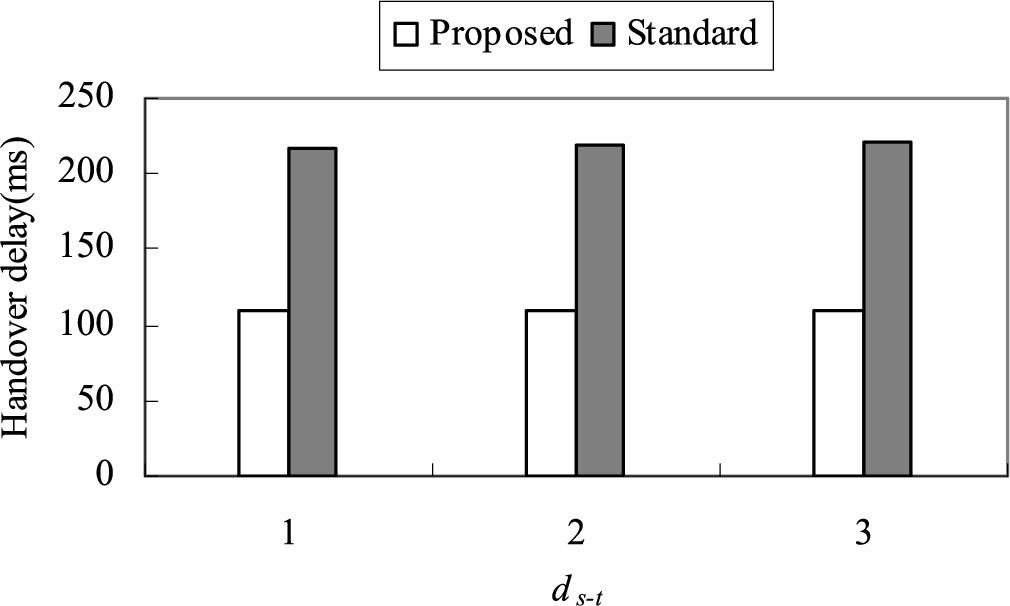
Handover delay based on
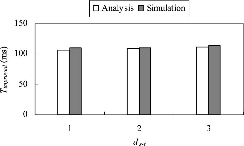
Handover delay improvement based on
As shown in Fig. 8, the handover delay in the proposed scheme tends to be stable and is hardly affected by
In this scheme, the target AR directly assigns a CoA to an AMS, so the address uniqueness can be guaranteed without DAD.
This scheme employs the L2 messages to help achieve the CoA configuration and address binding.
In wireless networks, the L3 handover is launched after the L2 one is complete, so the total handover delay is the sum of the L2 handover delay and the L3 handover delay. In order to reduce the total handover delay, this paper proposes a cross-layering handover scheme and aims to minimize the effect of the L3 handover delay on the total handover delay. This scheme analyzes the message sequences in the L2 and L3 handovers, and studies the correlations between these L2 and L3 messages. Based on these correlations, this scheme combines the related messages in L2 and L3 and employs the L2 messages to help achieve the L3 handover including the CoA configuration and address binding. Consequently, this scheme substantially reduces the handover delay.
In our future work, we are going to extend this cross-layering handover idea to another attractive standard-LTE to achieve the objective of reducing the handover latency.
Footnotes
Acknowledgement
This work is supported by “333 Project” foundation (BRA2016438) and Jiangsu Nature Science Foundation (BK20141230).