
Abstract
Design ideation activities that involve the manipulation of geometry rely heavily on manual input. For feasibility reasons, the generation of design alternatives must often be limited, particularly when these alternatives need to be prototyped and tested. This paper describes a conceptual design strategy that leverages variational three-dimensional geometry to automatically generate a large number of design alternatives from a template model and their corresponding physical prototypes for evaluation and testing. In our approach, 3D geometric variations are produced automatically from a single design concept modeled parametrically, which are then used to generate 3D-printable files. Our method is suitable for design scenarios where real-world testing is preferred over virtual simulation and requires designers to consider a concept idea as a family of solutions, instead of a single design option. Our strategy enables an effective exploration of conceptual design spaces in highly constrained situations and facilitates parallel prototyping, which is known to produce better results than serial prototyping. We demonstrate the feasibility and effectiveness of the proposed method through a case study that involves the design of an instrument for ophthalmic surgery for extracting an intraocular lens (IOL) from the eye. Using our approach, nine unique concept families comprising a total of 150 designs were rapidly and successfully prototyped and tested.
Keywords
Introduction
Human-artificial systems collaboration is leading to new hybrid design approaches that leverage the integration of people, intelligent technologies, and artificial cognitive systems. Researchers Johnson et al. (2018) described this approach as “designing for interdependence” or “coactive design” (Johnson et al., 2018). The emergence of autonomous design tools does not mean that human designers will be replaced, but that the role of human designers is changing (Seidel et al., 2018), (Zhang et al., 2021). Human-machine collaboration has been explored in various stages of the design process including early-stage ideation (Camburn et al., 2020), later stage ideation (Yuan & Moghaddam, 2020a, 2020b), and concept evaluation (Camburn et al., 2020). Human-machine collaboration has also been examined as a support mechanism for managing design teams (Gyory et al., 2022), to aid teams in design configuration problem-solving (Zhang et al., 2021), and for the design of complex systems (Song et al., 2022, 2020), to name a few. Other authors have studied the transfer of design strategies from humans to computational agents (Raina et al., 2019). Systems leveraging these tools can become collaborative partners in the design process (Koch, 2017), reducing the cost and time required to design a new product.
Advances in engineering and computing technologies, particularly Computer-Aided Design (CAD) and additive manufacturing, have transformed many industries (Marion & Friar, 2019) and, as a general trend, they are being integrated earlier into the engineering design process (Marion & Fixson, 2021). However, many exploratory and ideation activities that involve the manipulation of geometry still rely heavily on manual input. In the present work, we describe a method that leverages variational geometry and Knowledge-Based CAD techniques to support the iterative phases of design ideation, prototyping, and testing. Our approach enables designers to automatically expand a single concept or idea into a wide range of design alternatives and produce the corresponding physical prototypes for testing and design evaluation. Additionally, our strategy facilitates the collection of greater amounts of data to inform the next iteration of ideas or the selection of the most suitable design candidate.
The paper is structured as follows: first, we review the relevant literature on computational tools and methods for conceptual design. Next, we discuss our proposed approach, which relies on the manual creation of parametric solid models that serve as templates for the automatic generation of design variations via parameter manipulation, and a custom module implemented as an add-on for a commercial CAD system that subsequently exports each design alternative to a 3D printable file. Finally, to illustrate and validate the feasibility and effectiveness of our approach, we present a case study of the design of an ophthalmic surgical instrument for extracting an intraocular lens (IOL) from the eye.
Background
During the early stages of the design process, designers formulate a number of design concepts and alternatives, often through sketching. The development of these alternatives as well as the related decision-making processes to identify the most suitable design candidates can be complex and time-consuming, as designers must strategically explore the design space within the design requirements of a product. This exploration of design alternatives is key during the conceptual design phase (Liu et al., 2003). Various procedural design methods have been applied to the concept exploration phase of product design, typically focusing on aesthetic variations. For example, Hsiao and Chen (1997) proposed a semantic and shape grammar-based approach for product design, illustrating their method through the design of an office chair (Hsiao & Chen, 1997). McCormack et al. also applied shape grammars to product design with a focus on maintaining brand language and identity (McCormack et al., 2004). Prats and colleagues (2009) laid out a vision for a system in which designers design shapes and a system computes shapes independently of each other, and these two parts would interchange information. The designer would define sketches and shape rules and give this information to the computer system. The computer system would compute shapes that prompt and inspire the designer. The design concepts explored in their paper were all represented and iterated as 2D sketches (Prats et al., 2009). These approaches successfully synthesize shapes by emphasizing the visual attributes of the form. However, the functional elements, which require a more refined control and careful variation of certain dimensional elements and geometric relationships of the design, are sacrificed over aesthetics.
Recent advances in CAD and computer graphics technology have enabled the use of more powerful and intelligent techniques which can automate various aspects of the design process (Khan & Awan, 2018; Marion & Fixson, 2019), including the creation of geometry (Müller et al., 2021; Ramnath et al., 2019). Although CAD tools have primarily been used to analyze, validate, and fabricate designs, they are increasingly used earlier in the engineering design process and are replacing traditional physical prototyping methods (Kazi et al., 2017; Marion & Fixson, 2019). These tools can make certain tasks more efficient and improve the overall quality of outcomes in cases of complex yet repetitive tasks (Kreis et al., 2021a).
Alcaide-Marzal et al. (2020) leveraged CAD software in a 3D shape generative method for aesthetic product design. Rather than capturing 2D grammars, they used 3D by using grammars to capture product appearance, used sketch transformation rules to produce design variations, and used a parametric modeler to build 3D models of the varying shapes. Their conceptual generative model (CGM) was built in Grasshopper and Rhinoceros software and included both numerical parameters to drive dimensions and categorical parameters to determine if geometry would be present or not. Focusing on aesthetic product design, they showed examples of their method applied to products like an office chair, coffee maker, perfume bottle, and motorcycle (Alcaide-Marzal et al., 2020).
While shape grammars are very useful for exploring aesthetic product variations of products with pre-defined functions, such as chairs or bottles, they are not as applicable to engineering design problems. In engineering design, Knowledge-Based Engineering and Knowledge-Based Design are approaches that can increase efficiency in technical problem-solving. Knowledge-Based Engineering (KBE) has the goal of reducing time and cost in product development through the automation of repetitive design tasks and the reuse of engineering knowledge (Gembarski et al., 2017; Verhagen et al., 2012). Knowledge-Based Design (KBD) is a subfield of KBE that focuses on procedures to support design processes by “reusing predefined methods, algorithms or results, and it is integrated into specific tasks or workflows that are involved in the design processes” (Hirz et al., 2013). Authors Kreis et at. refined this definition to describe Knowledge-Based CAD as a “systematic integration of knowledge into the design models by use of parametric-associative and feature-based design with extension of problem-specific solutions, e.g. in form of template models” (Kreis et al., 2021b). Knowledge-Based CAD implements automated routines, functions, and rules into the CAD model to integrate specific product knowledge into the design process. The implementation of different types of knowledge-based design methods and tools can be performed at various levels, as illustrated in Fig. 1 (Hirz et al., 2013). Applications of Knowledge-Based Engineering (KBE) in general, and Knowledge-Based Design (KBD) in particular, have been described in the context of aerospace and automotive development (Kreis et al., 2021a; La Rocca, 2012), manufacturing (Zheng et al., 2022), and the overall product lifecycle (Cho et al., 2016; Pugliese et al., 2007).

Different types of knowledge-based design applications (adapted from (Hirz et al., 2013)).
Although a broad range of functionalities and applications have been included under the umbrella of KBD, including the use of “rigid models” (i.e., non-parametric geometry provided for re-use in component libraries and databases), authors agree that KBD starts with variational geometry, i.e. the parameterization of geometric objects throughout the design process (Hirz et al., 2013). Indeed, parameterization is a foundational element in the proposed approach described in this paper, not only in terms of the technology but also as a modeling strategy. The fact that a model has been parameterized does not mean that it can be easily modified so it can adapt to changes. In this regard, an effective parameterization strategy during the modeling process is a prerequisite for automatically generating variations of the geometry.
Modern CAD systems for engineering design are based on feature-based parametric solid modeling technology, which provides mechanisms to incorporate semantics, geometric relations, and algorithms to effectively convey and embed design intent in CAD models and assemblies (Otey et al., 2014). Parametric feature-based models are created by combining high-semantic level geometric elements known as features in a hierarchical manner via parent/child relationships. This associative structure of feature dependencies drives the geometry and enables reusability. When the dependencies are defined properly, any change to a feature will automatically propagate to the dependent features, regenerating the geometry in a predictable manner.
The ability to use mathematical or logical relations (e.g., formulas, rules, etc.) to define and drive the geometry of a 3D model is a core characteristic of the parametric modeling paradigm. At a higher level in the taxonomy, automated routines for geometry creation or calculation procedures are performed by integrated scripts, which enable designers to automate the generation and modification of geometric elements through software code and template models. Template models are a type of generic variational model prepared specifically for reuse. Finally, interactive applications represent software modules that are embedded in the CAD application (not the model) and usually take the form of macros or software add-ons in the CAD environment. They are software solutions that support specific engineering tasks.
One barrier to the implementation of CAD automation and KBD methods in the design process is the initial effort required to create template models, algorithms, and routines. In some cases, continuous maintenance is needed to keep KBD tools up-to-date (Hirz et al., 2013). In addition, designers who use autonomous software tools need to change their design work strategies in order to make effective use of the tools. Designers must often use different mental models that fit with the tools and build new capabilities for framing design problems and evaluating ideas (Seidel et al., 2018). Nevertheless, during conceptual design, even small interventions can enhance the creativity of design teams in their process of generating concepts (Deo et al., 2019; Salvador et al., 2014). For example, intentionally building on the ideas of others has been found to be a high-performing method in enhancing creativity during the concept generation phase (Deo et al., 2021). Likewise, modeling a single idea in a configurable manner in CAD and automatically generating multiple variations provides designers an opportunity to expand a single concept into many possible solutions, and possibly inspire new concepts that had not initially been considered. To this end, developing a clear understanding of how Knowledge-Based CAD, particularly those methods based on parametric feature-based geometry and automated routines, fits into the engineering design process is key.
Physical prototyping is another phase of the design process that is known to be time-consuming, particularly when multiple design variations are being evaluated, due to the manual work involved and the iterative nature of the activity (Dering et al., 2018). The nature of the prototyping process can also make it difficult to automate (Dering et al., 2018). Some authors have discussed methods that avoid the need for physical prototyping altogether, such as computational prototyping approaches using digital human modeling (DHM) to simulate ergonomic interactions with virtual prototypes (Ahmed et al., 2021). This DHM approach is not suitable for all situations, as not all human-tool interactions can be simulated easily and reliably.
Although many physical prototyping methods, materials, and tools exist, the popularization and affordability of additive manufacturing technologies has had a significant impact on prototyping tasks. The ability to print complex structures with minimum waste directly from the digital 3D model is one of the main benefits of 3D printing (Ngo et al., 2018). The opportunities enabled by the combination of CAD and additive manufacturing have already allowed for transformative innovation in many industries (Marion & Friar, 2019), yet more opportunities remain. Parallel prototyping has been seen to produce better results than serial prototyping (Dow et al., 2010). In this regard, the quick generation of multiple different 3D printed prototypes from a single CAD model could enable greater efficiency in the design process as a variety of alternatives could be tested and evaluated quickly before refining and iterating on the design. In this paper, we describe and validate an approach that combines the automation of geometric variations for shape exploration with additive manufacturing. Our method accelerates the exploration of design spaces and provides support to designers during decision-making processes.
In this section, we describe a design method that leverages Knowledge-Based CAD to aid human designer teams during the new product development process. The method is best implemented during the early-stage ideation and prototyping phase, after design requirements and user needs have been identified and defined. At this point, the design team works on developing a broad range of possible solutions as well as prototyping and testing those solutions to determine viability. Early-stage prototyping and testing is an iterative process – testing the performance of a prototype can lead designers to come up with more novel ideas based on their findings.
Our proposed method is best suited for situations where physical prototyping is preferred over digital prototyping or simulation, and where 3D printing is an appropriate method for creating the physical prototypes. However, parts of this method are still applicable and effective in cases where simulation or digital prototyping is viable. Our method is also especially suitable for situations where precision is needed in the final design solution. In such cases, comparing similar prototypes side-by-side to assess their performance would aid the design team in finding the best-performing solution.
A typical method used by design teams in early-stage concept development is illustrated in Fig. 2. Each circle represents a single concept or idea generated by the team. The most promising ideas are selected for prototyping, and individual CAD models are built to 3D print prototypes of those concepts. After testing the prototypes, the design team iterates on the ideas based on what worked or did not work, and the process repeats.
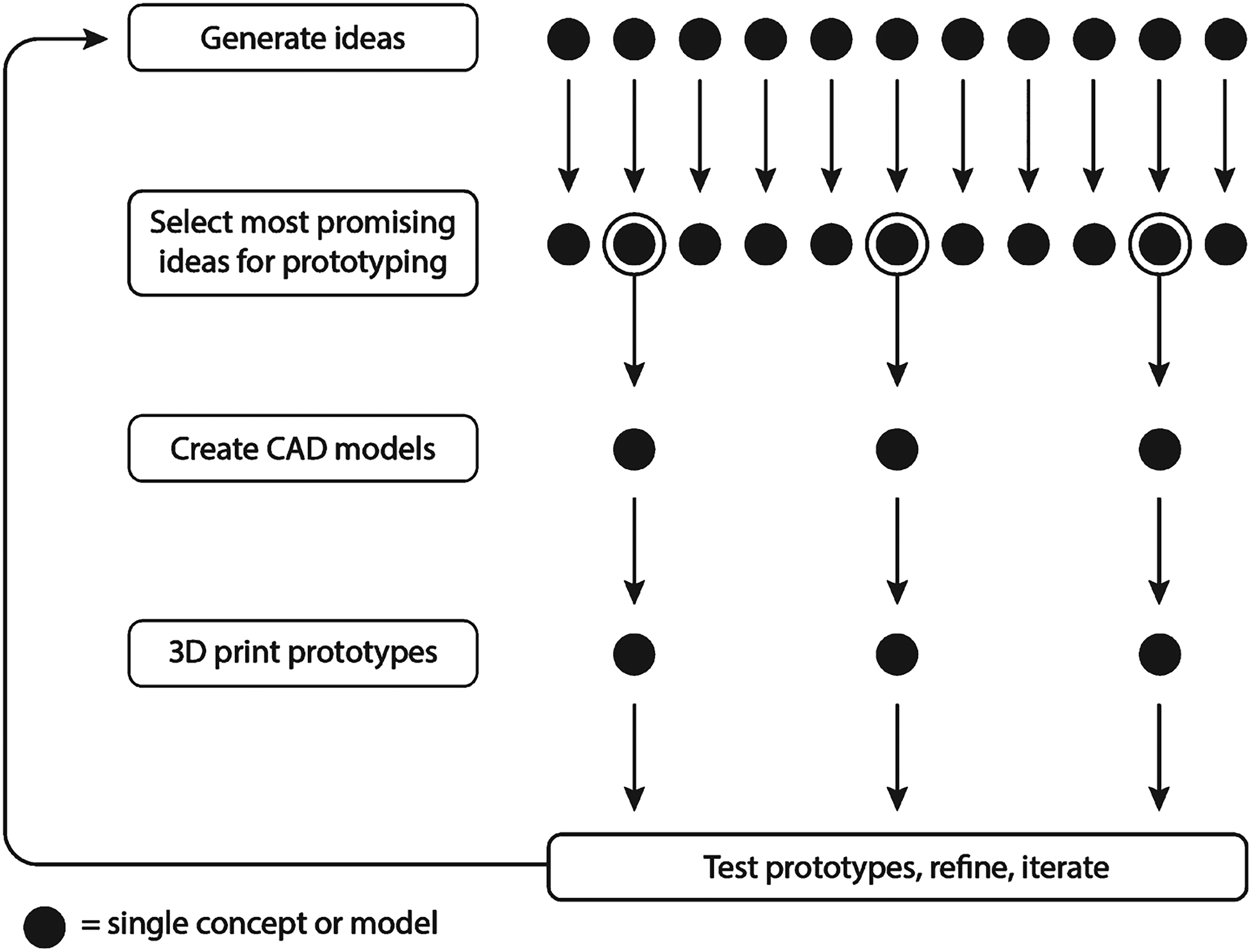
A typical method for early-stage concept evaluation and prototyping.
We propose a method where, following the selection of the most promising ideas from the initial ideation phase, the designer creates the 3D CAD models for these ideas. The models are then used to automatically generate design variations within a predefined range. Each configuration is a unique model which can then be 3D printed for further physical testing and analysis. The method is illustrated in Fig. 3.

Proposed method to generate more prototypes for early concept evaluation.
This strategy enables design teams to perform more testing in parallel rather than waiting for the next round of prototyping. For example, a typical prototype might be produced in only a single size, and the design team would not know whether the size was too small or too large until the physical prototype was produced and tested. The designer would then determine what changes need to be made, create a new model, and produce a new prototype during the next round of prototyping. In our proposed method, each prototype is modeled in such a way that multiple features are varied in size of dimension in a single configurable model. All of these configurations are then exported to a format suitable for 3D printing. As a result, many different variations of a single idea can be tested in parallel, allowing for a faster feedback loop in the iterative design process. In addition, our strategy allows the automatic expansion of each concept or idea proposed by the designer. By forcing themselves to think about each concept as a configurable design template, designers can naturally broaden the way they think about a concept as a range of possibilities rather than as a single fixed solution.
The effectiveness of the proposed method is highly dependent on the quality of the template models used to generate the geometric variations. In our paper, CAD quality is defined in the context of parametric geometry and reusability, as described by Company et al. (Company et al., 2015). Since the models required in our process are parametric, the use of geometry that is efficiently parametrized, flexible, and robust is critical. Otherwise, design alternatives may not be created successfully due to regeneration errors. To a great extent, the quality of the template model is ultimately the designer’s responsibility. They must ensure that a good modeling strategy is applied (Camba et al., 2016, 2014) so that model variability is maximized (Aranburu et al., 2022a, 2022b). In this regard, designers must think about a template model as a family of design solutions, instead of a single design option.
In order to generate variations of the initial concepts automatically, we leveraged a design evaluation and optimization tool that is available in a commercial CAD system (i.e. Design Studies, which is fully integrated within the SolidWorks environment). Other CAD systems provide comparable functionality through similar tools (e.g., Design Studies in Creo Parametric, or Geometry Optimization in Siemens NX).
The design optimization tool allows designers to specify ranges of variation for selected design variables (usually dimensions) in a particular template model. The software then iterates through the various combinations of the values, generating the corresponding geometric combinations within the defined design space. An example is shown in Fig. 4.

Design generation process using the Design Studies tool in DS SolidWorks. Eight different bottle designs are generated from a revolve feature by varying three dimensions in the sketch shown in the bottom left.
To facilitate the creation of the physical prototypes, a custom software module was developed that leverages the capabilities of the SolidWorks API. The module traverses through all the geometric variations generated in the previous step and exports the geometry of each configuration of each model to a Standard Tessellated Geometry (STL) file for 3D printing.
In the following section, we describe a case study of the early-stage design of a surgical tool for ophthalmology to further illustrate our proposed method and validate its feasibility and effectiveness.
We describe a case study of a co-design process involving an ophthalmologist who collaborated with a design team to co-develop an improved method and a surgical instrument to extract a defective or undesirable previously implanted intraocular lens (IOL) from the eye during a surgery to potentially exchange for a new IOL or leave the patient without an IOL. There is currently not a tool or surgical instrument that is dedicated to this procedure. The current standard of care involves using generic forceps to grip the IOL (these forceps are used to grip many different things) and cutting the old IOL in half with micro scissors prior to removing it (these micro scissors are also used for various other purposes and are not dedicated to this procedure). This technique poses risks to the eye and relies on a device that could mechanically fail (Lee & Webster, 2016). Instead, a decision was made to explore different concepts and develop a new dedicated instrument based on the idea that the IOL could be folded into a tube-like device and extracted from the eye via that device, which might reduce the size of the incision needed and reduce other risks during the procedure.
In the context of eye surgery, sub-millimeter dimensions are considered critical, and there is a goal of reducing the size of any incisions made in the eye during procedures. Thus, the project was an ideal test-case for our proposed method, because varying different dimensions of the prototypes would be necessary in order to find the smallest possible functional size of the instrument. The design team was uncertain about which shapes would facilitate the folding of an IOL, so a variety of shapes needed to be tested. Our proposed method allowed the design team to create slight variations of each concept to determine which variation best facilitated the folding of the IOL.
In this case, virtual testing and simulation were not considered appropriate, in part because of the difficulties surrounding simulation of flexible materials in computer software. The IOLs are flexible and also come in varying shapes, materials, and thicknesses (Bellucci, 2013; Findl, 2009), so even a single well-set-up simulation would not be adequate to model their folding behavior. Additionally, the procedure would be performed inside the cornea of the eye, which is full of aqueous fluid, making it an environment which might also be difficult to simulate. Ergonomics were also an important concern given the surgical nature of the instrument. Therefore, the design team chose to rely on real-world testing of prototypes to evaluate design concepts.
3D printing is increasingly being used by ophthalmologists for novel device development (Akkara & Kuriakose, 2018). For this project, we selected material jetting as our 3D printing technology and acrylic for the material. The process and material were selected based on their suitability for creating small, highly detailed models. A semi-transparent acrylic was selected so that the designers could better determine how the IOL was bending inside the device. For production, 3D prints were ordered in batches from Shapeways, a commercial 3D printing company.
Throughout the design process, nine unique concept families were prototyped and tested. Models from each concept family are shown in Fig. 5. Within each concept family, many variations were prototyped and tested. The design team went through 12 rounds of ideation and prototyping, testing 150 different 3D-printed prototypes in total. As the team observed the folding behavior of the IOL entering the device, the designers came up with new ideas for how to facilitate the folding. Initially the designers thought a large, angled opening would best facilitate folding, as shown in the models on the left-hand side of Fig. 5. As the process continued the design team explored other ways of folding the IOL, including using variates slits to facilitate rolling up the IOL. Finally, a curved slit was determined to be best as it allowed for some flexibility of the plastic device and allowed the IOL to stay partially protruding from the device during the folding process.

Initial design concepts. Multiple variations were made of each of these designs using configurable CAD models.
The design team determined the range of parametric dimensions for each concept based on their best estimates of what might work given their knowledge of dimensions of the other instruments involved in the procedure, such as the IOLs and the forceps. We limited the design space for the variations in our study by identifying a set of functional dimensions that were most likely to change for these types of parts in an ophthalmic context and the natural constraints given by the average size of the human eye. The dimensions and the respective ranges of variation for all the parts were determined based on the experience of a professional ophthalmologist as an effort to ensure the shapes are fully functional, coherent, and reasonable both in size and shape, while keeping the computational cost of generating these variations under control. An example of how these parameters were controlled and varied for concept A are shown in Fig. 6. Three parameters were varied in concept A to generate the 27 different models: the inner diameter of the tube, the curvature profile of the opening (controlled by three cutting profiles), and the length of the opening. A selection of the 3D models that were generated from this base model are shown in Fig. 7. The use of the Design Studies feature in SolidWorks saved the design team a lot of time in the modeling process, because instead of creating divergent individual models for each variation within a concept family, the team made a single base model and generated all the variation from there.

Parameters varied in concept A to create 27 different 3D-printed models.

Some of the 3D models generated from the parameterized model in Fig. 6.
The base model used to generate the concept A models tested in round 2 of prototyping is shown in Fig. 6. In total, 27 variations of concept A were generated from the base model and 3D printed for testing. Further time was also saved by using the custom software module to batch export the STL files for 3D printing, rather than opening and exporting many individual models. The 3D printed models are shown in Fig. 8.

3D-printed SLA prototypes tested in round 2 of prototyping for concept A.
The physical prototypes were first tested outside the eye, and the most promising prototypes were then tested with pig eyes in a wet lab. Figure 9 shows prototypes being tested both outside and inside of the eye. The functionality of the final solution is illustrated in Fig. 10. The IOL is inserted into the tube, and the curved edges and slit at the tube’s opening facilitate the folding of the IOL as it enters the tube.

Prototype being tested outside the eye (left) and in a pig eye (right).

Functionality of the final design solution.
In this paper, we presented a method of human-computer collaboration in the design process through the use of Knowledge-Based CAD and additive manufacturing. The method was successfully applied in a case study involving the design of a novel instrument for ophthalmic surgery. The strategy significantly reduced the time in the overall design process by enabling the design team to quickly test a wide range of variations of 3D-printed prototypes in each round of prototyping.
Similar to the conclusions drawn by Alcaide-Marzal et al. (2020) in their study on aesthetic forms, our approach also enables the communication cycle between human and computer described by Prats et al. (2009). In our case, however, we particularly emphasize the parametric attributes of the model, the exploration of design families, and focus on design scenarios where real-world testing is preferred over virtual simulation, rather than leveraging other techniques described in the literature such as reformulation of the structure, behavior, or function of the design (Gero and Kannengiesser, 2004), building analogies (Goel, 1997), or looking for emergent features (Eastman, 2001).
In a typical design process, a team might make a single prototype to represent each of their best concepts. In our case study, the team tested a large number of design concepts by leveraging CAD automation techniques to make as many as 27 variations of any single concept. All these design alternatives were generated automatically from a single 3D template model through the use of variational geometry and a design evaluation and optimization tool. The files for 3D printing were also generated automatically from each configuration using a custom software module.
The design team evaluated 150 prototypes in total over 12 rounds of revision and testing. By applying the proposed method, designers were able to save modeling time and avoid repetitive work of re-creating similar models or exporting each model individually for 3D printing. They were also able to expand the range of possibilities of a single design beyond what they might have come up with had they modeled each prototype individually. Although the prototyping phase is known to be time-consuming and difficult to automate due to its physical nature (Dering et al., 2018), we found the use of variational geometry to be a beneficial timesaver. The process also enabled the use of a highly parallel prototyping method, which is known to produce better results than serial prototyping (Dow et al., 2010).
Some authors have pointed out that designers who use autonomous software tools need to change their own ways of working in order to make effective use of the tools (Seidel et al., 2018). The proposed method did indeed require the designers to think about their concept ideas differently. Instead of thinking of each solution as a single option, designers had to think of each solution as a family of solutions. This idea is key for building a high-quality template model that can react to geometric changes in a robust and predictable manner, and determining how different parameters could be varied to generate different designs within a single concept.
The line of thinking described earlier was suitable for this project, and for the proposed method in general, due to the number of unknowns and the highly constrained nature of the design space. For example, the design team did not know how small of a tube they could get an IOL to fold into, but they could make an educated guess about the range of sizes that might work, and then set the parameters to vary within that range. Likewise, the team did not know which shapes would best facilitate folding, but they could draw different profiles and then vary the model to make use of those different profiles.
Likewise, our approach requires designers to learn about the mental model embedded in the computational tool being used (a parametric modeler, in our case), as described by Allen (1997). Designers must possess not only a comprehensive knowledge of the artifacts they aim to produce but also the proficiency to effectively navigate and control the software tools employed in their creation, particularly the effective parameterization of the geometry. In this regard, the utilization of autonomous tools in design necessitates that practitioners not only grasp but also engage dynamically with the tools’ cognitive frameworks (Seidel et al., 2018).
Although successful in highly constrained situations, the proposed method may not be as appropriate for design briefs with much more open-ended solution spaces, because the designers have to define definite constraints within each model. In addition, the approach may reduce the potential for creativity in these cases, as design solutions are generated through automatic variations of the template model, which is inherently limited and may inhibit the development of outstanding new solutions. Contrasting examples of situations with open ended solution spaces where a more open-ended approach of generative design is appropriate include fashion design (Yuan & Moghaddam, 2020a, 2020b) or video game design ([47]Seidel et al., 2018). In these cases, many different solutions are desired to create a family of garments or a variety of virtual worlds. In our case, however, the goal was generating a single viable solution under relatively limiting constraints.
Conclusions
Computer-Aided Design (CAD) tools are being used earlier in the design process and are replacing traditional physical prototyping methods (Marion & Fixson, 2019). CAD tools are also implementing increasingly more intelligent features which automate the design process (Marion & Fixson, 2019). In this work, we leveraged parametric design optimization as a method to explore the solution space for a functional design problem, the design of a novel ophthalmic instrument. To the best of our knowledge, no other methods have been described that leverage the automation of parametric 3D solid model geometry to enhance the conceptual design process by facilitating the effective exploration of design spaces in highly constrained situations.
We described a new method of leveraging Knowledge-Based CAD techniques and tools in the early stages of the design process. Our method uses CAD automation to generate multiple configurations of a design from a single model that has been built with variational geometry. We then use a custom module to automate the process of generating STL files for 3D printing. Our method enables design teams to expand a single concept or idea into a variety of physical prototypes for testing and evaluation, giving them a greater amount of data to use as input for the next iteration of design refinement. The method we propose can be implemented by professional design teams interested in a computer-supported exploration of design spaces to find new solutions to a particular design problem, or by design educators who are interested in instructing design students in more advanced, data-driven methods of using CAD software for prototyping.
Our findings contribute to the literature concerning the integration of design creativity theories with geometry optimization and generative computing methodologies. In this context, our efforts are directed towards the refinement and expansion of these techniques, including the creation of flexible product architectures and their corresponding workflows, as well as the applicability to more geometrically complex product structures, including assemblies (Otey et al., 2019). We posit that the successful enactment of intelligent computer-aided conceptual design requires a transformation in our current design paradigms, and it is important to consider these systems as entities of design themselves, rather than mere tools for the design process. In this context, the design process becomes a collaborative activity between human and computer, rather than a computer-supported, but purely manual, task.
Our method was validated through a case study involving the co-design of a tool for ophthalmic surgery. Through multiple iterations of prototyping and testing using this method, a successful design solution was created and patented. Following the case study, we realized that the proposed method could be further improved in multiple ways. For one, labels or identifiers could be automatically incorporated into each model, to eliminate the manual step of labeling each prototype by hand prior to testing (see hand-made labels in Fig. 8). This step could be incorporated within the CAD automation process, as the parameter values could be used to create embossed or debossed labels on a tab at the end of each model, for example. Another improvement in the process would be for 3D modeling software to incorporate features that automatically check models for viability in different 3D printing methods, such as evaluating for minimum wall thickness. We are interested in exploring these possibilities as future work.
Another limitation of this method would be the 3D printing technology used in the project. In our case, we ordered 3D prints from a commercial company and there was not a limit to the printing capacity. When a new batch of prints came in, the entire batch of prototypes was tested. An individual designer who is also supervising their own desktop 3D printer may be better served by a linear prototyping and testing workflow rather than our proposed method. However, with the growing availability and affordability of commercial 3D printing services, we envision that our method could be appealing to many design teams.