
Abstract
With the penetration of multi-source and multi-type distributed generation (DG) in distribution network, the power flow calculations of distribution network become more and more complex. On the premise of analysis of power flow calculation model for different DG, this paper presents a power flow parallel computing algorithm for complex distribution network based on multicore CPU technique. On the basis of analysis of topological structure of distribution system, the task assignment problems in the isomorphism multicore processors were solved to improve speedup ratio and parallel efficiency. Integrated with the characteristics of backward/forward sweep methods, a hybrid power flow parallel computing method was given to adapt for the nodal type of various DG. In order to test the convergence and parallel efficiency, the proposed algorithm have been tested on IEEE 90 bus and a composite system, which is composed of IEEE 20 bus, IEEE 90 bus, IEEE 37 bus and etc. The results show that the proposed hybrid power flow computing method is adaptive to the complex distribution network with multi-type DGs, and the designed parallel algorithm effectively shortens time of solving equations and multicore resources are fully utilized.
Introduction
In response to resource depletion and environmental degradation, the distributed generation (DG) using renewable energy, which includes solar energy, wind energy, water energy, bio-energy, geothermal energy and ocean energy, has been attracted extensive attention for their superior clean pollution-free properties and outstanding inexhaustible supply merits [1, 2]. With the maturity of technology and decent of price, the penetration proportion of DG in power system is becoming more and more large. This high penetration level necessarily brings out challenged technical issues to the analysis and computation of power system [3]. Due to difference from the conventional generation techniques, DG access controls to distribution network also change with the types of distributed generators [3, 4]. Furthermore, access of intermittent renewable energy resources makes distribution network increase plenty of uncertainties [5]. Therefore, when integrating intermittent DG into distribution network, the power flow computation is becoming increasingly sophisticated.
Additionally, due to high requirements for energy conservation, the improvement of the quality and reliability of supplying power, the interconnection of regional power network is an inevitable trend [6]. In future, the formation of large-scale interconnect power network will be one of the prominent characteristics of power systems. Conceivably, this necessarily leads to an explosive increase of information for power flow computation [7]. Consequently, the computational efficiency of the traditional power flow algorithm can’t meet the need of stability computation of interconnected network.
Fortunately, the rise and rapid development of the parallel/distributed computing technology has become a powerful ally toward greatly improving computation efficiency. As a basic of analyzing and studying various problems in power system planning and running, the power flow computation has been studied on basis of parallel/distributed computing technology. [8] presented an approach to parallelizing optimal power flow (OPF) adopting decomposition coordination methods, which can be used to coordinate a heterogeneous collection of utilities. By decoupling solution procedure of electrical system and control system, [9] put forward a microgrid transient simulation and parallel computing method. Integrated with the recursive quadratic programming method and the Lagrange projected gradient method, [10] proposed a distributed and parallel OPF algorithm for the smart grid transmission system with renewable energy sources. [11] proposed partitioning scheme for the nonsymmetric Jacobian matrices to achieve parallelization of LU factorization, giving the implementation on computing platform comprising a single-chip shared-memory configurable multiprocessor. In view of the characteristic of GPU (Graphics Processing Unit) compute-intensive, highly parallel computing, [12] put forward simplified Newton’s method applicable to GPU, and it has high computing efficiency. By adopting parameterization schemes, [13] presented a distributed continuation power flow method for voltage stability assessments of global transmission and distribution grid. For the distributed computation of load margin, the boundary bus voltage, load parameter and equivalent power are communicated between the transmission and distribution control centres in correction step. Based on message-passing distributed-memory architecture with separate workstations, [14] presented a parallel and distributed computing framework to solve Newton–Raphson load flow of the large interconnected power systems.
With the improvement of computer hardware, multi-core became the mainstream. It provides opportunities and challenges for solution of complex power system problems. [15] presented a multi-core parallel algorithm employed to power system analysis, which fully utilized both computer hardware resources and computing power. To allocate each node to processes, [16] mapped radial distribution networks into the tree structure of multi-processor system, and employed communication between the root processor and leaf processors to realize the parallel computation for distribution power flow based on forward/backward sweep approach.
Different from above research, based on multicore CPU technique, this paper gives a parallel computing method for the power flow of complex distribution network with multi-source and multi-type DGs. For one thing, by analyzing the topological structure of complex distribution system, the task assignment problems were designed to improve the computational efficiency by making full use of the resources of multicore computer. For another thing, a hybrid parallel computing method of power flow was given based on the equivalent current injection technique and backward/forward sweep methods. The proposed algorithm have been tested on modified IEEE 90 bus and a composite system, which is composed of IEEE 20 bus, IEEE 90 bus, IEEE 37 bus and etc. under different multicore computer. Simulation results are analyzed and discussed.
Parallel task assignments based on the topological structure
The having published documents show that computational efficiency of power flow is the strongly correlated with the number of bus and feeder as well as the specific structure of distribution network [17]. In order to improve computational efficiency of power flow for the large-scale complex distribution network and take full advantage of multi-core processor resources, this paper divided the large-scale distribution network into several sub-network corresponding to task queue of parallel computing. For realization of task assignments, an efficient branch and node numbering scheme are developed, and layer node numbering matrix, forward-linked branch matrix and backward-linked branched matrix are employed. Subsequently, the task queues are formed by partitioning distribution network, which is finished by analysis of the topological structure. Furthermore, task assignment and speed up are given according to the number of feeders and node.
Numbering scheme
The node numbering is developed in layer away from the root node to simplify network, while the branch numbering is the same as the secondary nodal number of one branch [12]. Then the simple branch matrix, which denotes the association information between nodes and branches, is achieved by cyclic searching and logical reasoning. Figure 1 shows schematic for distribution network numbering. On this base, the terminal branch matrix and the next-linked branch matrix are obtained.
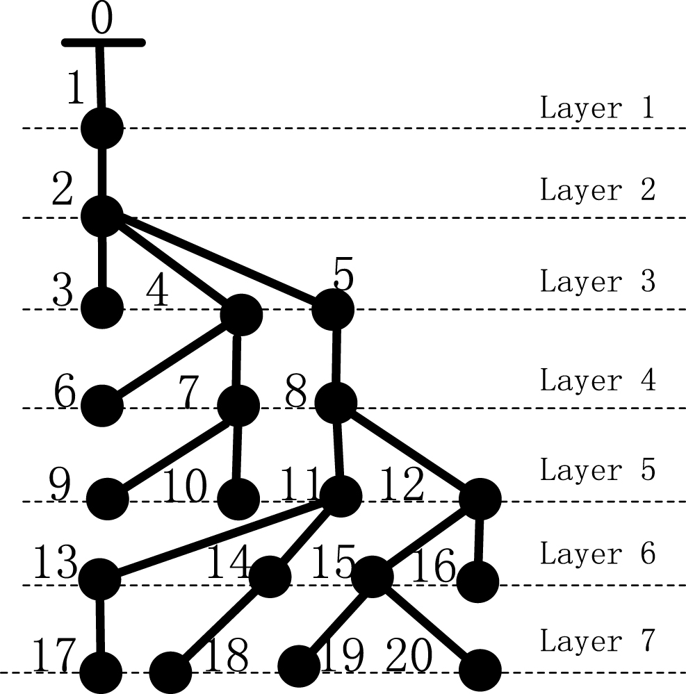
Schematic for distribution network numbering.
For the simple branch matrix, the row number represents layer number, the non-zero element in matrix represents the branch number, which is also the receiving node number of the branch.
The terminal branch matrix is proposed to reduce the search space and improve computing efficiency effectively. Similar to the simple branch matrix, the row number represents layer number, but the non-zero element in matrix only represents the terminal branch number.
The next-linked branch matrix is proposed to adapt to the power flow as well as to improve the search efficiency. The row number represents branch number, the first column element represents the starting node number and the other column contains receiving node numbers. The non-zero element in matrix represents the number of receiving node while zero denotes there is no receiving node. Additionally, the next-linked branch number of one node is generally no more than five in distribution network, so here a n×6 matrix is adopted. In Fig. 1, the next-linked branch matrix is a 20×6 matrix.
The subtask is obtained by dividing whole distribution network into several sub-networks, which must be independent and connected graph. The subtask queue is a ranked list in descending order according to sub-network scale. For the formation of each sub-network, this paper adopts the limited depth-breadth priority algorithm [18] to search the distribution network starting from endpoint according to given the threshold for sub-network scale, which is defined as the maximal node number included in sub network. And the searching is self-determination and intelligence due to the application of efficient numbering scheme, layer node numbering matrix, and forward-linked branch matrix. The principle and realization of the limited depth-breadth priority searching algorithm are described as follow.
Selection of the searching initial point
In real distribution network, the next-linked branch number of one node is usual two or three, which makes the branch number of the first four layers less than 20. In addition, the interconnectivity of the whole of power flow for power system is undeniable in the most basic sense. Therefore, the searching initial point responding to each task should be terminal branch, which has not next-linked branch. And the searching initial point excludes the first four layers to improve search efficiency.
Setting of the threshold for sub-network scale
In order to take full advantage of multicore resource, parallel tasks need to keep balance as much as possible. However, formation of sub-network is related to the structure of distribution grid. The unreasonable setting of sub-network scale can result in the unbalance task on cores. Therefore, based on the branch number, a threshold λ is designed to limit the sub-network scale to keep load balance as far as possible. That is to say, the branch number included in each sub network must not be larger than threshold λ, which can be estimated by expertise or the number of processor cores and branch of distribution networks. Here the threshold λ is denoted by Equation (1).
A subtask corresponding to a sub network is obtained by the combine of depth and priority search strategy [18, 19]. The search begins from terminal branch and ends when the branch numbers don’t satisfy the sub-network scale. During the searching process, depth search is firstly used, and then breadth search is carried on. The two search methods are used alternatively until the subtask is obtained. Based on this method, all the subtasks are given.
To understand it more clearly, let take Fig. 1 as an example to explain the formation of a subtask. Assuming that threshold λ is 10, and the branch 20 on the biggest layer is chosen as the first branch. By carrying on the depth search, the forward-linked branch 15 is selected as the second branch. Then by width search, the branch 19 is looked as the third branch. Subsequently, by the depth search, forward-linked branch 12 connected with branch 15 is selected. By analogy, branch 16 and branch 8 are added. When the starting point of the search is reached branch 8, the search results include branch 11, 13, 14, 17 and 18. If they are chosen, the sub-network scale is 11, which has gone beyond the threshold 10. Therefore, to assure the independence and connectivity of the sub-network, the branch 8 is deleted. Therefore, a sub-network is composed of branch 20, 15, 19, 12, 16. Similarly, all other sub-networks can be obtained.
Task assignment of multi-core processors
Under multi-core environment, speed-up rate and parallel efficiency are two important indexes of measuring the performance of parallel algorithms and availability ratio of multi-core resources [20]. The speed-up rate and parallel efficiency η are given in Equations (2 and 3).
Load on each core has important effect on improving parallel efficiency [20]. In order to take full advantage of the hardware, here the parallel computing is implemented in a multi-threaded or multi-process manner to ensure tasks allocation of each core, avoiding unbalance. The number of thread is consistent with that of core on the system. The task assignment is achieved by running queue, which is a list of subtasks sorted by priority value. The priority is determined in accordance with sub-network scale representing the bus/branch number. The higher the sub-network scale, the higher the priority. This task queue is shared by all processes. Each core executes a select task in accordance to task priority. When one core finished a task, it selects the next task from task queue, and the selected task is removed from task queue. Each core keeps doing this until all tasks have been executed.
The previous research indicated that the method of backward and forward is good for power flow calculation of radial distribution network, but this method still exist some disadvantages in solving large-scale complex distribution network with loads of PV nodes or loops. Therefore, in view of the characteristic of the back/forward sweep method and equivalent technique, three types of DG model are included and the weakly looped network is also presented. Subsequently, integrated with the complexity of distribution network with DG, the power flow parallel calculation is proposed to effectively decrease computation time and improve computation efficiency.
Equivalent injection current
The application of the equivalent injection current is for many reasons [21]. For one thing, the penetration rate of DG is constrained, which result in a fact that distribution system with DG still keeps the characteristics of radial operation. For another thing, it is conducive to the implementation of the parallel computing. Furthermore, it can not only accomplish calculation of equivalent current at one time, but also reduce workload and improve high efficiency.
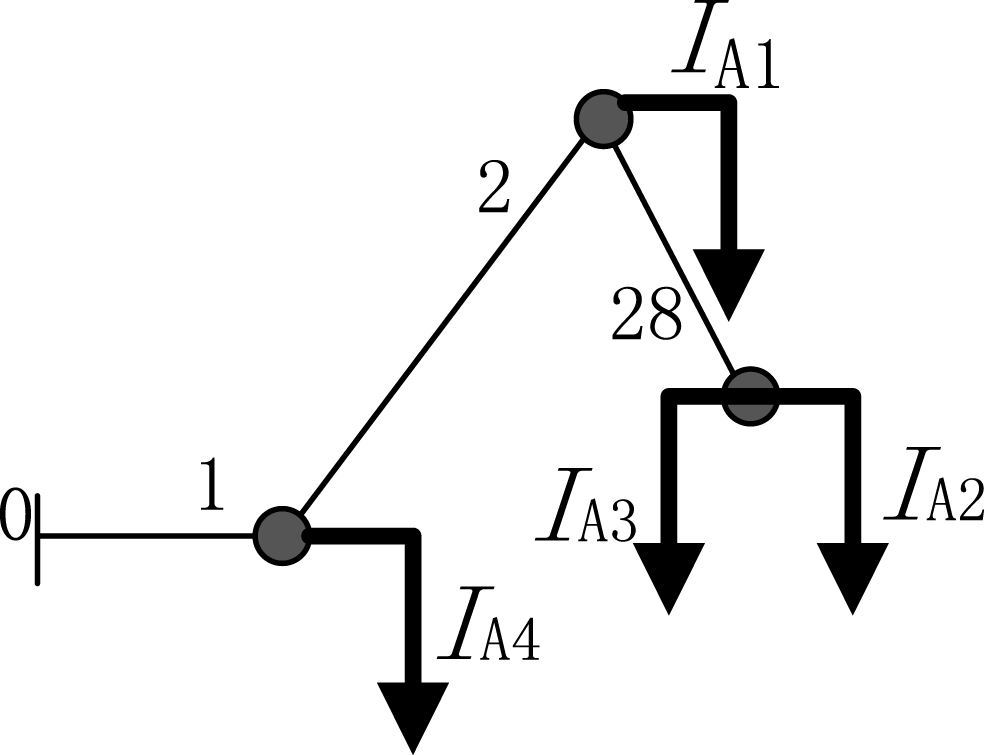
Here the equivalent injection current is used to replace the sub network obtained from task allocation scheme in section two. Assuming that Fig. 2 is a sub network, then its injection current is equal to the current through branch 1, which can be calculated by Equation (4).
Schematic for load and branch.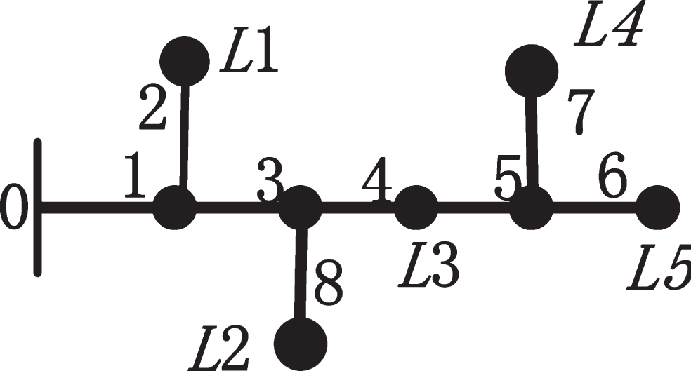
The voltage drop at each bus corresponding to bus 0 is obtained with branch-current and branch impedance vector (Z) specified in Equation (5)
The backward and forward method is applied to power flow calculation of equivalent distribution network. The backward and forward power flow calculation is presented based on the equivalent injection current. The iterative solution formulas for the i - j branch include: Branch current for the backward step
Nodal voltage for the forward step
According to the interface method, DG model for power flow can be classified essentially into three kinds of models such as constant PQ model, constant PV model and P is constant while Q is the function of outgoing port voltage magnitude, which is named as PQ (V) model. In comparison with the ordinary loads, the representative form of DG power is basically similar, but DG power works in an opposite direction. Therefore, here all kinds of DG are taken as negative load, and the equivalent current injection techniques are employed to model them according to their unique character [21].
In addition, the backward and forward method has merits of simplicity, reliability and rapidly convergence in solving power flow of the radial distribution network, but it does have also some disadvantages in dealing with weakly looped distribution systems with PV buses. About treatment of constant PV model and loop, reactive correction of PV Model and open loop method have been frequently used in literatures [23–25]. Here the proposed method in our previously published literature [22] is still employed. And we only give the reactive correction of PV Model shown in (8), active and reactive correction of breakpoint from open loop shown in (9). Their basic principles and derivation process can be found in [22].
Concurrently, considering with complexity of power flow calculation and topological structure of distribution network, the numbering scheme for DG and opened loop are further modified to easily computing and programming. Sticking with the preceding node numbering scheme of distribution network, the node for DG and open node of loop are orderly successively numbered based on the type of DG and breakpoint from loop. All DG is thought to be connected with distribution network through a virtual branch with zero resistance and zero reactance. After finishing the number of distribution network, PQ DG, PV DG and PQ (V) DG orderly continue to number. Then two breakpoint from loop continue to be numbered. The advantage for this number scheme is following: Flexibility of DG access to distribution network. Whether location of DG or number of DG access is changed, the number can be rapidly finished without taking into account structure of distribution network. Convenience for power correction. Due to the relations among buses, branches and the third elements (e.g., DG number, loop number, DG layout, communication overhead between CPU, etc.), power correction for PV DG and two breakpoints from loop is mostly implemented in serial operation mode, which can make a big difference to the efficiency of computer. Successive number of same type DG is more rapid and more convenient in processing power correction due to omitting search process. Improvement of computational efficiency. This successively numbering scheme based on classification is simple, flexible and easily achieved, without tedious search in power flow calculation. Therefore, when it is applied in a larger scale and complicated distribution network with DG, the computation time adds up to a criticalsavings.
For the sake of more clarity, let us take Fig. 3 as an example. The left of Fig. 3 shows the topological structure of network, while the right of Fig. 3 gives the schematic for number scheme of DG and breakpoint from loop. Here assumed that PQ DG is located in bus 4, PV DG is accessed to bus 8 and bus 10, PQ (V) DG is connected to bus 6 and loop is R1 and R2. The virtual branch is marked with fine line, while the hollow circle is the representative of breakpoint from loop.
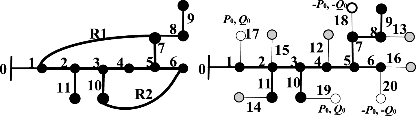
Schematic for the number scheme of DG and breakpoint from loop.
The power flow parallel computing mainly makes up of data preprocessing and power flow calculation which rationally uses the combining method of serial and parallel. The parallel calculation mainly refers to calculation of the equivalent injection current for the sub-network. The flowchart for power flow parallel computing is shown in Fig. 4. Data preprocessing process is mainly concerned with the numbering of DG and breakpoint, obtainment of resistance/reactance matrix, formation of subtask queue, etc., which are achieved by means of serial processing. In order to avoid some irrational phenomenon that multiple cores perform the same task or lost task, the spin lock is employed to implement the concurrency control of task execution [26, 27]. If a task is locked by a process, no other process can operate it even read until that the task is finished and unlocked.
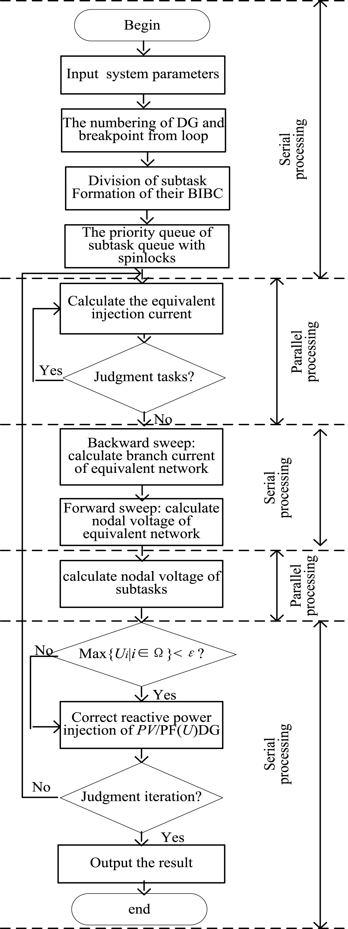
Flowchart for power flow parallel computing.
To demonstrate the performance of the proposed power flow parallel computing method, simulation studies are implemented by the Java technology on a PC, which is powered by a 2.5-GHz Intel Core 2 Quad processor and 4GBs of RAM. IEEE 90 bus system and a composite system are employed to analyze and discuss the convergence, computation speed and parallelism of the proposed algorithm. In power flow calculation, power base is 10MVA and convergence accuracy (ɛ) is 10–4.
Simulation for IEEE 90 bus with various DG
IEEE 90 bus is selected as the simulated system by connecting various DG. Its topological structure is shown in Fig. 5 and the load number is represented in Fig. 6. The branch, load parameters are founded in [29]. The test involves six types of scenarios as following:

Topological structure and partition of IEEE 90 bus.
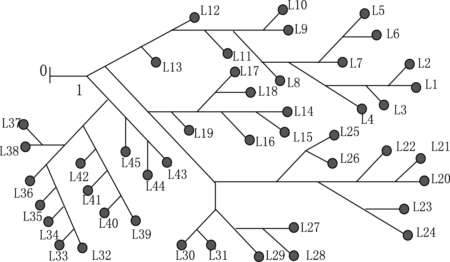
Topological structure of IEEE 90 bus.
In order to verify the impact of DG and loop number on the result, this paper conducted abundant experiments by changing DG number, loop number and the initial value of active/reactive correction under each scenario. Table 1 listed the tested parameters for different DG. The impedances of the given two loops are 0.0002 + j0.0005 and 0.0082 + j0.0246. In addition, here set the threshold λ= 30, then the sub-network include four areas: A1, A2, A3, A4 shown in Fig. 5. The sorted subtask queue is A4, A1, A3 and A2. The equivalent network is shown in Fig. 6. The number of load bus is shown in Fig. 7.
Parameters for different DG
Equivalent network for IEEE 90 bus.
Simultaneously, the simulations using Digsilent PowerFactory15.0 have been done to verify the validity of power flow method. Figures 8 and 9 show the voltage profile of 45 loads bus corresponding to here proposed method and Digsilent PowerFactory15.0. The first five scenarios in figure refer orderly to without DG, two loop, two PQ DG, two PV DG and two PQ (U), while the sixth scenarios involves one PQ DG at bus 20, one PV DG at bus 66 and one PQ (U) at bus 29. For loop information, One branch B1 is placed between bus 63 and bus 28, while another branch B2 is between bus 11 and bus 19. For PV DG, the initial voltage is 1.02p.u., and the reactive power is zero. When opening the loop in accordance with the previous presented method, the initial active and reactive powers of all breakpoints are equal to zero.

The voltage profile of 45 loads from the proposed method in this paper.

The voltage profile of 45 loads from Digsilent Power Factory 15.
Taking simulation using Digsilent PowerFactory15.0 as reference, the maximum relative error of systematic load bus is computed to clarify credibility of the presented method. The equation is shown in (10) [28].
Maximum relative error under different scenarios
In addition, loads of simulations are carried out under different number of core to test the parallel performance of algorithm. The number of CPU core, the calculation time and speed-up rate for IEEE 90 bus is shown in Table 3.
Calculation time and speed-up rate for five scenarios
A composite systems, which is composed of IEEE 33-bus, 90-bus, 37-bus, modified-16 bus, 69-bus and 20-bus, is to further analyze the computation speed and the parallel performance of the proposed parallel algorithm. The test system data of 90-bus comes from [29], while that of 16-bus, 33-bus and 69-bus can be founded in [30]. The details for 37-bus and 20-bus come from [31, 32] respectively. The schematic of connection of composite systems is shown in Fig. 10. Table 4 lists load balance degree, computing time and speed-up rate in different number of processor cores.
Load balance degree, computing time and speed-up rate for a composite system
Load balance degree, computing time and speed-up rate for a composite system
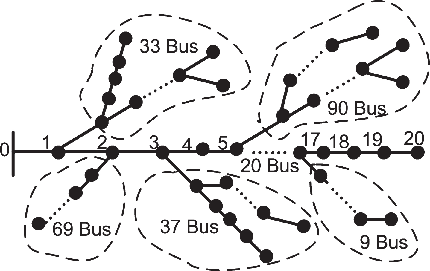
Schematic of connection of composite system.
By analysing and studying the results measured, some following conclusions are obtained: The proposed parallel power flow calculation method had better adaptability to the weakly looped complex distribution network with different types of DG. And it can reach demanded accuracy in short time. The results also show the correctness and the affectivity of the proposed method. Loads of simulation experiments show that different DG has different impact on the convergence of the algorithm. PQ DG has little influence on convergence of the algorithm, while PV DG and PQ (U) have a greater impact which is closely related to DG location, DG number and selection of initial values. Whether PV DG or PQ (U), generally speaking, the larger the access number, the longer the computational time. Furthermore, when location is inappropriate or access number is excess, convergence speed is slow, or even cannot get a convergence solution. Furthermore, the initial value of reactive has some influence on the convergence of the algorithm. The good initial values can effectively accelerate convergence velocity of iteration. The location and number of loop have significant impact on convergence of the algorithm. With the increase of loop number, computing time is generally increased. The various location of loop has significant effects on computational time. Similar to PV DG and PQ (U) DG, the slow convergence speed or divergent phenomena also will occur while the improper loop exists. The initial value of active/reactive for breakpoint has also influence on the convergence. The appropriate selection of initial value can get rapidly convergent solution. From Figs. 8 and 9, The voltage magnitude at each load bus is almost completely same. From Table 2, the relative error is various with the change of DG type. And the maximum relative error is only 0.048%. It shows that the proposed method in this paper is validity in solving the power flow of complicated distribution network with multiple type DG. From Tables 3 and 4, the computing time reduce gradually with the increase of the processor number. Conversely, the speed-up rate increase gradually with the increase of the processor number. But the change of speed-up rate does not match with that of processor number. The key reasons are due to the imbalance of load allocation on the different core. Plenty of simulation results show that the computing time is affected by task allocation scheme. When tasks are evenly allocated on each core, the computing speed can increase remarkably with the number of processor cores increasing, and vice versa. Therefore, in order to make full use of CPU processing ability, the tasks should be equally allocated on each processor as far as possible.
Conclusion
Aiming at large-scale weakly looped complex distribution network with multi-type and multi-source of DG, a high efficient power flow method is given by making good use of the parallel design of algorithm and a reasonable assignment of tasks queue, greatly reducing the computing time. Plenty of simulation results show that the proposed hybrid power flow computing method is adaptive to solve power flow of complicated distributed network with multi-type DG. When the location of DG or loop is appropriate, the algorithm will rapidly converge. While the location of DG or loop is unfit, the non-convergence will happen. The designed parallel program can shorten the time of solving equations and multicore resources are fully utilized. The simulation results also show that the presented method is simple, effective and suitable to dealing with complicated distribution network with multiple type DG. Although the simulation on three imbalanced networks is not done, the presented method provides clues for the power flow calculation of three phase imbalanced networks. Only by slightly modification, it can be used on three phase imbalanced networks with DG. And here presented conclusions can offer a reference for system operators, planner and real engineering application.
Footnotes
Acknowledgments
This work was supported in Hebei Natural Science Foundation of China (No. F2015204090), Science Research Project of Hebei Higher Education (Nos. QN2016063, ZD2017036), Technology Foundation of Agricultural University of Hebei (Nos. LG201601, LG201602, LG201605) and Oversea study projects for the youth backbone of Hebei Agricultural University.