
Abstract
Currently the matrix vibration of the strapdown inertial navigation system (SINS) for some cruise missile needs to be reduced and conventional algorithms occupy excessive hardware resources. Considering the vibration frequency range from 50 to 400HZ has the biggest impact on the guidance accuracy, we propose a target method for active vibration control in the SINS. Firstly, the requirement analysis is carried out for the target method, and secondly the MATLAB software is used to design the parameters and compare the filtering simulation. Then the hardware design is performed and the filtering algorithm is improved to reduce the power consumption approaching green computing. Finally the effectiveness and cost-efficiency of the target method for active vibration control in the SINS is verified by the experiment. The results show that the target method can separate the main vibration frequency which affects the guidance accuracy with a good linearity effect, efficient hardware utilization and low power consumption approaching green computing. Moreover, the accuracy, the effectiveness and efficiency of the control algorithm have been also significantly improved.
Keywords
Introduction
Vibration is present in many dynamic mechanical systems. Vibration control is the effort to reduce the negative effects of vibration effectively. Two main groups of vibration control methods are passive and active methods. Passive vibration control methods include elimination of additional energy sources, eliminating or decreasing input forces and isolation from external disturbances. Unfortunately, the use of passive vibration control methods is not effective because of inefficiency in the range of low frequencies, sensitivity on application conditions, lack of robustness, and increased size and weight. On the other hand, these methods allow dissipation of a great deal of vibration energy in the range of sufficiently high frequencies (energy dissipation increases with decrease of passive elements stiffness). Better vibration control results may be achieved by using active methods. Active vibration control (AVC) methods work by providing an additional energy supply to vibration systems. These methods alleviate the problems of contradictory requirements imposed on passive vibration control techniques, such as efficiency of device operation, low frequency vibration, dynamic stability, stiffness, etc. The additional energy supply can produce a force that compensates the forces that account for vibrations. To reduce the vibration, the additional energy should have appropriate power, frequency and phase, relative to existing vibration forces. AVC methods can change the system parameters in an active way. The research in active vibration control (AVC) has been expanding since Lueg’s work in 1930s, and especially rapidly in the past three decades. The concept of AVC has been known for more than 60 years. The basic ideas of AVC were proposed in 1936, when Paul Lueg first described the design of active noise control in a patent published in the United States. The continuous progress of AVC involves the development of improved adaptive signal processing algorithms, transducers, and hardware. Since the characteristics of the vibration source and the environment are time varying, the frequency content, amplitude, phase, and vibration velocity of the undesired vibration are not stationary. An AVC system must therefore be adaptive in order to cope with these variations. AVC systems can be used in linear or nonlinear control problems.
Strapdown inertial navigation system (SINS) has the advantages of low cost, as well as excellent performance, and has been widely used in various types of applications including tactical missiles and spacecraft. However, the substrate of SINS is directly attached to the solid matrix, which is exposed in harsh and complex vibration environment during the launching and flight, that the accuracy of the SINS is affected and a strong vibration can also result in instability and even damage of the electronic components. Currently, the solutions for accuracy degradation caused by substrate vibrations are mainly based on error compensation and passive damping. The error compensation is not applicable for some error factors, and passive damping is inflexible in terms of control. In order to weaken the vibration of the substrate, therefore reducing the impact of vibration on the inertia-sensitive devices, we proposed an active vibration control method based on intelligent structural for cruise missile SINS system. An FPGA-based FIR digital filter are introduced before the intelligent structure active control algorithm, in order to allow the active vibration control only for the vibration frequency greatly affecting the guidance accuracy [1].
The requirements and methods of the filter design for SINS active vibration control
Analysis of matrix vibration signal
According to the findings of relevant research institute, the range of the vibration frequency which will affect operation of SINS is mainly 10-2 kHz, and 50–400 Hz has the most significant impact on the accuracy. Simulation results showed that the actual vibration frequency affecting the SINS is generally less than 2 kHz, which is consistent with the findings. Therefore, it is necessary to remove the high-frequency component in the SINS vibration by introducing the digital low-pass filter.
The design steps of the active vibration control filter
Compared to other filters, FIR filter has two outstanding advantages, one is the system stability, and the other one is the strict linear phase-frequency characteristic while maintaining arbitrary amplitude-frequency characteristics. Therefore, it is feasible to introduce the FIR digital filter in intelligent structure active vibration control algorithm to separate the signals. The goal of filtering technique is to minimize the filtering time and optimize the performance. In this study, the FPGA is used to implement the FIR filter due to the faster processing speed resulted from the system parallelism compared to other types of general-purpose processors [5–8].
The basic steps of designing the filter are as follows. First according to the practical application background and the engineering requirement, make clear technical targets by determining the amplitude and phase response in the frequency domain. Secondly, it is necessary to make the approximation, that are the technical targets are defined, the model of the digital filter should be established; Then using MATLAB to design a practical filtering model to approximate the given targets. Finally, the hardware implementation and experimental verification of the filter are performed [9–12].
Design and simulation of FIR filter
According to the characteristics of the vibration signal of the strapdown inertial navigation system, the parameters of the filter design in this study are as follows: Passband frequency 100 Hz, sampling frequency 100 kHz.
FDATool toolbox of MATLAB is used to design the filter. Firstly, a Kaiser window function filters with order of 50 is used to introduce the design steps. The amplitude frequency and phase frequency curves are shown in Fig. 1.

Amplitude-frequency and phase-frequency diagram of Kaiser Filter design by FDATool Kit.
The performance of the filter is assessed by using superimposition of 100 kHz sampled 400 Hz and 2 kHz sine wave signals in Simulink. The simulation layout is shown in Fig. 2.
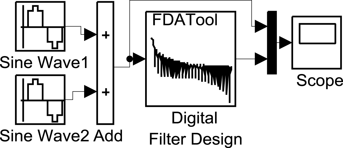
Simulink Layout diagram.
Sine Wave 1 is 400 Hz sine signal generator and Sine Wave 2 is 2 kHz sine signal generator. The combined two sine waves after the Add module go through the Digital Filter Design module (the filter designed by the FDATool toolbox) which is followed by the waveform display module Scope to visualize the results. The Scope1 module is used to observe the output waveform of the two sine signal generators. Scope module is used for result observation. Channel 1 shows the results after the filter and Channel 2 shows the waveform before the filter. The simulation results are shown in Fig. 3.

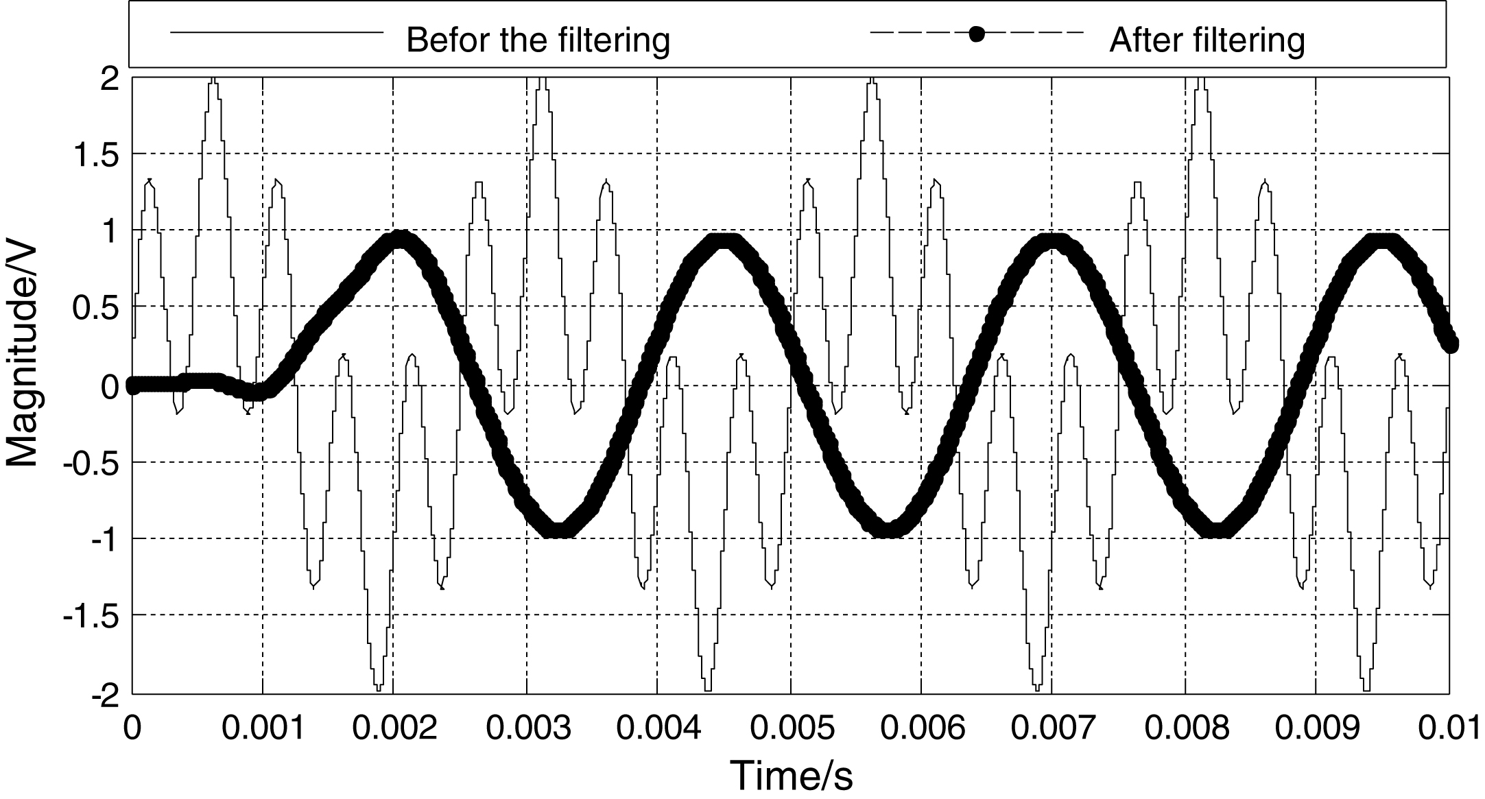
Simulation results of the Kaiser filter.
The same method is used to design the Butterworth type IIR filter and Chebyshev filter. The simulation results obtained in Simulink are shown in Figs. 4 and 5.

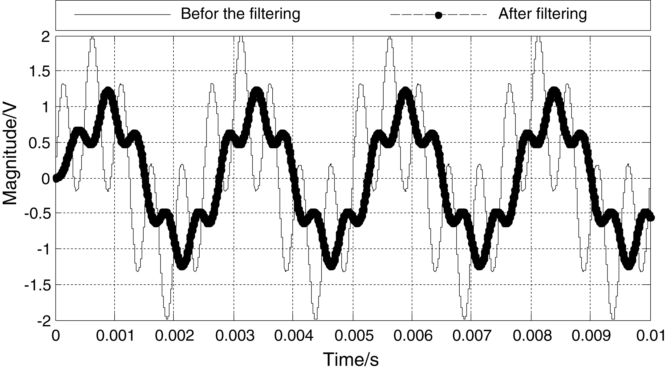
Simulation results of the Butterworth filter.

Simulation Results of the Chebyshev filter.
Then the FIR filter and Generalized FIR filter are designed and the simulation results obtained in Simulink are shown in Figs. 6 and 7.

Simulation results of the Equiripple FIR filter.
Simulation results of the generalized Equiripple FIR filter.
Finally, the Bartlett window function filter and the Taylor window function filter are designed using the FIR window function method, the simulation results are shown in Figs. 8 and 9.

Simulation results of the Bartlett window FIR filter.
Simulation results of the Taylor window FIR filter.
By comparing the simulation results of the above filters, the filtering effect of Butterworth IIR filter, FIR filter, Bartlett window function FIR filter and Taylor window function FIR filter are not ideal. Chebyshev filter has large delay and does not perform well. Only the Kaiser window function filter and the generalized FIR filter remove the 2 kHz signal from the 400 Hz signal. But the delay of the generalized FIR filter is high and therefore the Kaiser window function filter is chosen as the active vibration control filter for the strapdown inertial navigation system.
By using the “Export” command in the FDATool toolbox, the 50 order FIR filter tap coefficients h(0)∼h(50)are exported to MATLAB workspace and recorded.
Tap coefficient coding
The tap coefficient coding has to be considered in hardware implementation because the tap coefficient of FIR filter is normally a signed decimal. Common coding techniques are binary code, anti-code, complement and signed numeric representation method. In this study, the optimized SD coding is used to improve the utilization of the resources: The decimal numbers is represented using addition and subtraction of 2
n
, and –1, 0, 1 are used to represent numbers, while-1 is denoted by
Usually the efficiency of multiplication is indicated by the number of non-zero elements. For instance, the calculation process of A • x [n] is:
If:
Is:
It can be seen from the formula (3) that the efficiency of multiplication has a direct relationship with the number of non-zero elements a k in A. SD coding used here can effectively improve the efficiency of multiplication. Taking the first tap coefficient in formula (1) as an example, it requires eight adders after the first equal sign for conventional binary encoding and only seven adders are needed for SD coding after the second equal sign.
The FIR filter features with finite-length sequence for unit impulse response. So the function of the system can be written as:
Algorithm structure is shown in Fig. 10, where N is the length of h (n) (the number of taps), H (z) is (N-1) order polynomial of z-1 and it has (N-1) zeros in the z-plane. The origin z = 0 is (N-1) order multiple poles, so H (z) must be stable [1–4].
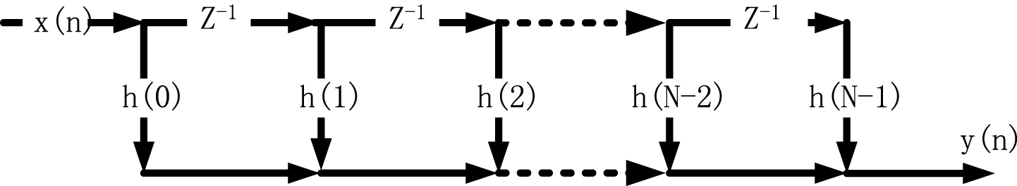
FIR filter structure of the FIR filter.
The FIR filter with this structure can be easily implemented by using adders. Figure 11 is a implementation scheme of the direct type FIR filter.
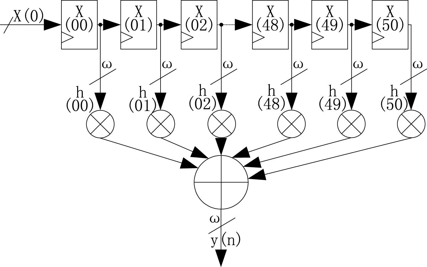
Implementation scheme of the direct type FIR filter.
In summary, this scheme is not ideal in terms of speed as well as resource utilization.
Unit impulse response of FIR filter is real and meets even symmetry or odd symmetry condition [5–7]. So the output of the filter can be written as:
This type of filter reduces the number of multipliers in accordance with the conditions of symmetry, thus saving device resources. The structure of symmetrical FIR filter is shown in Fig. 12 [8–10].
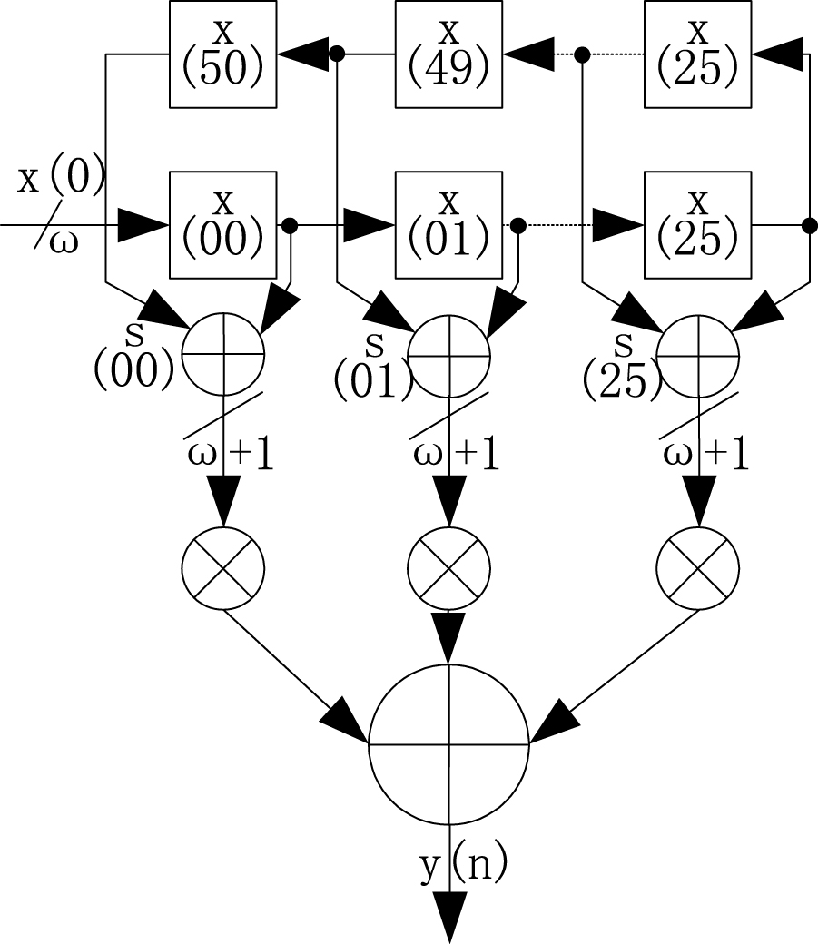
Structure of the symmetric filter.
Thus, the filter output we used can be written as follows:
Then we take the SD coding of the tap coefficients which are expanded 20 times as a set of matrix A.
The multiplicand which is multiplied with the tap coefficient is also taken as a set of matrix B:
We can obtain:
Then directly adding each column of the resulting matrix and unifying the displacement, we can get final algorithm formula.
Compared with the algorithm shown in Fig. 12, the hardware utilization can be reduced by 25%, effectively saving the hardware resources and obtaining enough space of the calculation for the active control algorithm and data preprocessing.
FIR filter experiments
Based on the proposed scheme, a simple experimental set-up is designed and implemented to verify the performance of the FIR filter, as shown in Fig. 13.
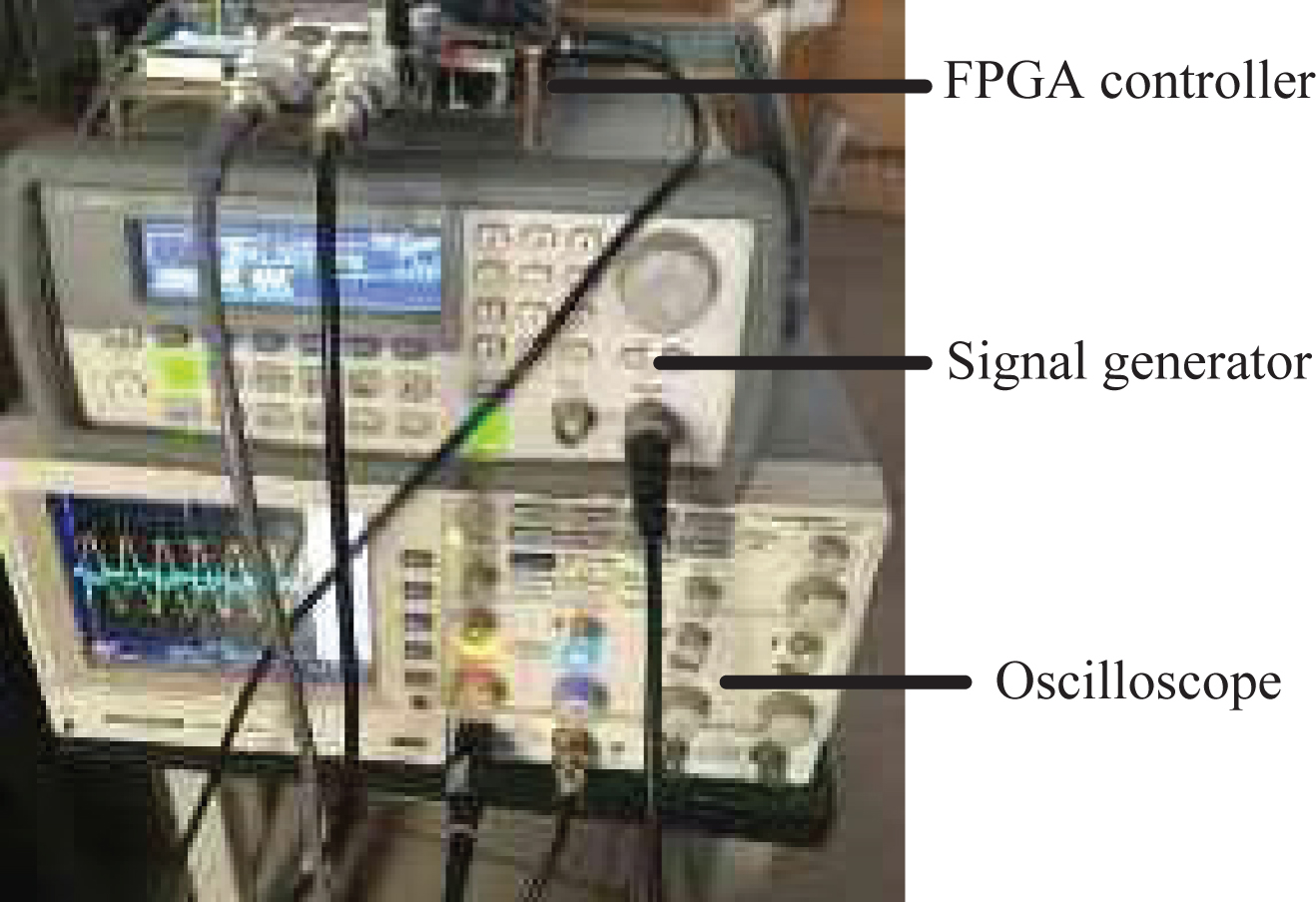
Experiment system.
In the experiments, the 40 Hz and 2 kHzsine waves coming from the signal generator are sent to the FPGA controller, respectively. The outputs of the signal generator and the FPGA controller captured by the oscilloscope are shown in Figs. 14–16.
Before and after filtering at 40 Hz.

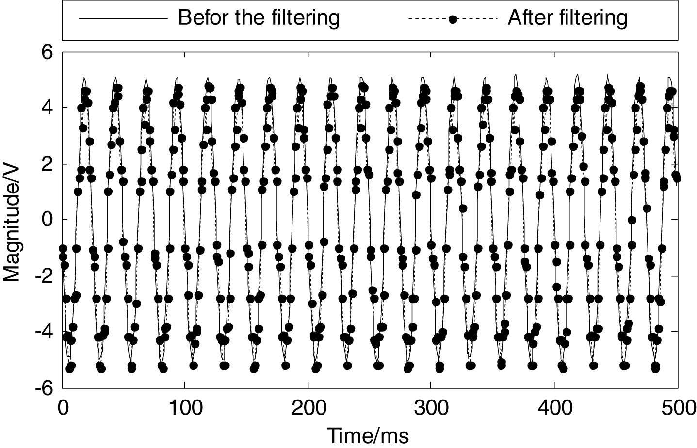
Before and after filtering at 400 Hz.
Before and after filtering at 2 kHz.
In Figs. 14–16, Channel 1 is the waveform of the signal generator, and the other channel is the filtered waveform. 40 Hz output in Fig. 14 retained the original characteristics. In Fig. 16, the output at 2 kHz has been filtered out and is close to a straight line. The experimental results have shown the good filtering performance which matches well with the simulation results.
However, obvious delay has been observed in the waveforms before and after filtering in Fig. 15. Then the output of the signal generator has been adjusted to record the phase difference before and after filtering at the different frequencies. The results show constant phase difference of 400. Considering the target frequency range of 50Hz–400 Hz for our SINS active vibration-control system and the half-period delay required for the vibration control algorithm, such stable phase difference can meet our application requirements.
By adjusting the function generator to output signals with different frequencies, the peak-to-peak amplitudes after filtering are recorded and illustrated in Fig. 17.

Peak-Peak value/frequency data graph.
Result shows that after the filtering, there is a linear decrease of the peak-to-peak amplitudes for frequency ranging from 100 Hz to 2000 Hz. For frequency higher than 1000 Hz, the output amplitude is below 5 V which satisfy the requirements of SINS matrix active vibration control.
To verify the effect of the FIR filter on the SINS matrix active vibration control, the following experiment system shown in Fig. 18 has been built up.
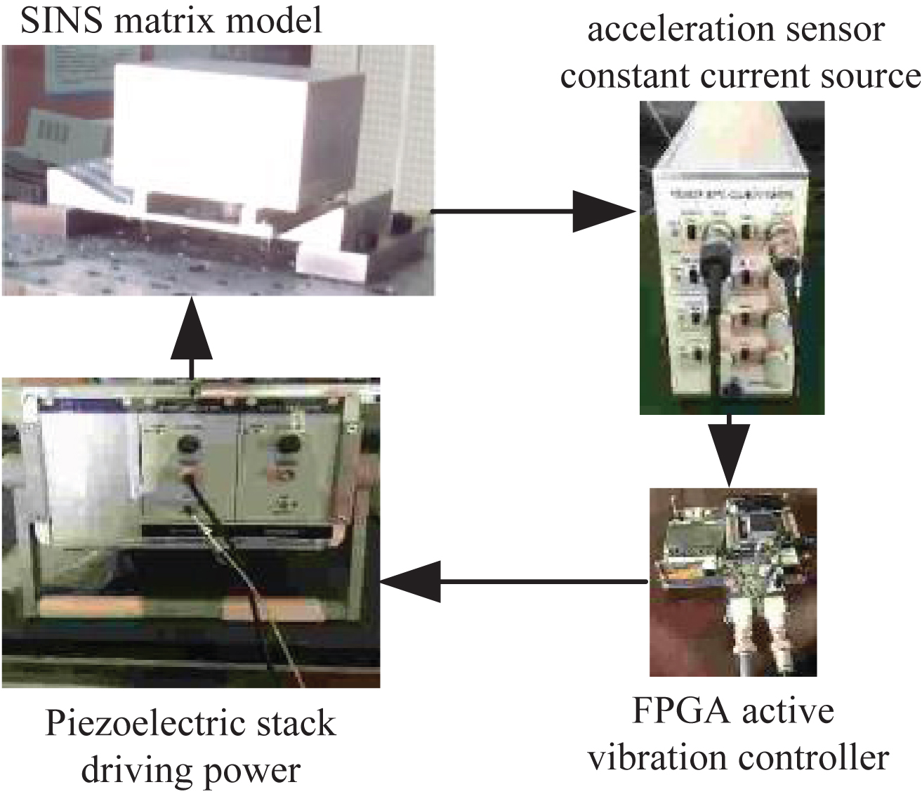
Experimental system of the SINS matrix for active vibration.
In the experiments, the impact load is applied to the SINS matrix model through the hammer. The vibration signal is then captured by the acceleration sensor constant current source and sent to the Flash of the FPGA active vibration controller.
The vibration effect diagram of the SINS matrix drawn in MATLAB is shown in Fig. 19:
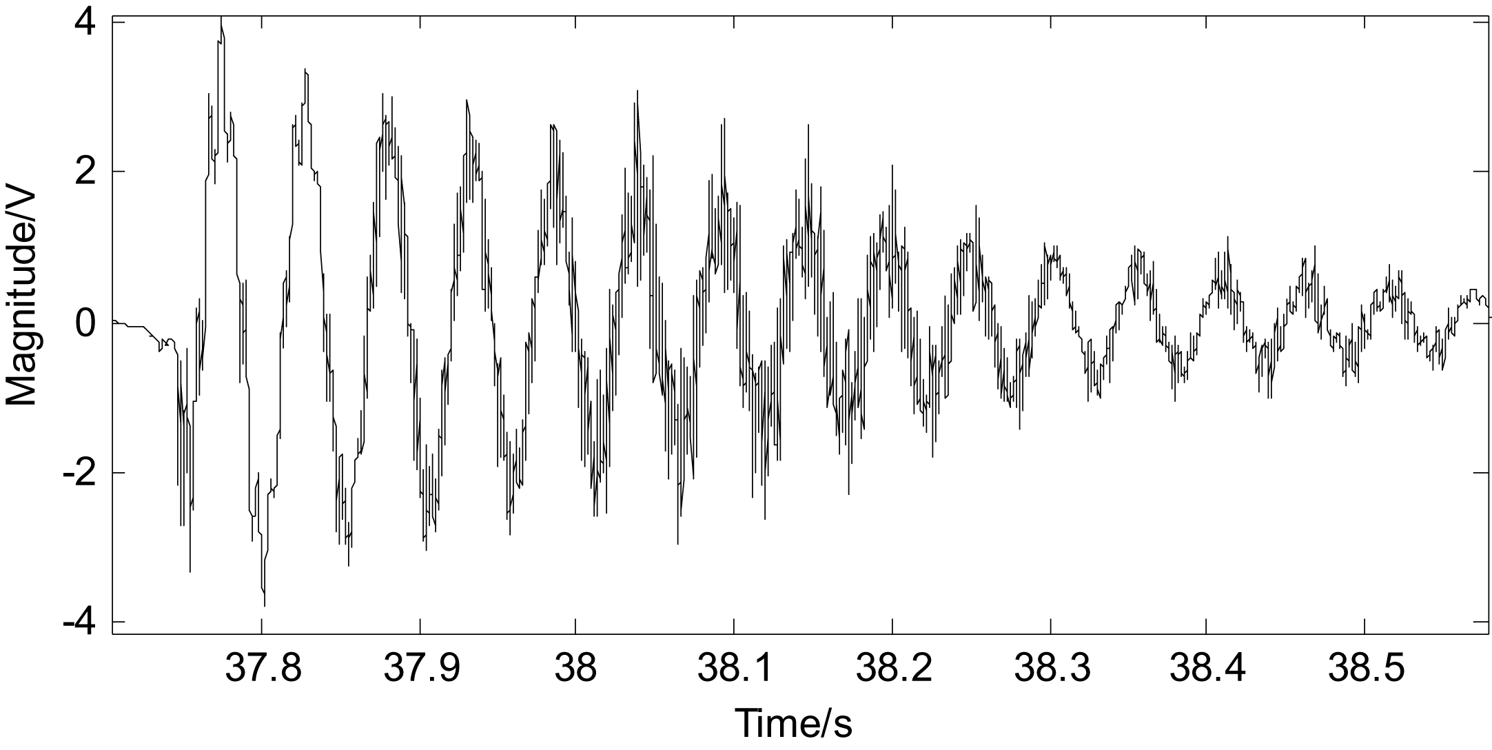
Before the filtering by SINS matrix for vibration.
The impact load is applied again to the SINS matrix model by the hammer and the vibration signal is captured and sent to the FPGA active vibration controller. It is then processed by the designed FIR and the filtered signal is stored in the Flash.
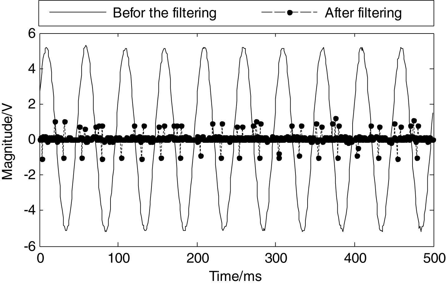
The filtering effect of the SINS matrix vibration is plotted using MATLAB and presented in Fig. 20.

After filtering by SINS matrix for vibration.
It can be seen from Figs. 19 and 20 that the designed filter has a good filtering performance. The vibration curve of the SINS matrix is smooth, which can completely indicate the vibration characteristics of the SINS matrix. The filtered vibration signal of the SINS matrix will be further used for active vibration control algorithm.
In this paper, based on the analyses of the active vibration control for the Strapdown Inertial Navigation System (SINS) in a certain cruise missile and the evaluation of hardware resource utilization, we have investigated the target frequency method used for the front-end of the active control algorithm. MATLAB is used for designing the parameters and simulation comparisons. The comparison results meet the requirements of the active vibration control of the Strapdown Inertial Navigation System (SINS). The filtering experiments verify the filtering effects of multiple frequencies, which are consistent with the simulation results. Finally, the experimental analysis of the matrix model in a virtual reality environment shows that the proposed method can achieve smooth matrix vibration curve, which can completely reflect the matrix vibration in Strapdown Inertial Navigation System (SINS), and therefore can be used for active vibration control algorithm. The proposed method can effectively improve the accuracy, effectiveness and efficiency of the control algorithm. The issue of separating the main matrix vibration frequency which affects the guidance accuracy is solved. The designed target method for Strapdown Inertial Navigation System (SINS) matrix active vibration control has the advantages of good linear effect, low hardware utilization, and low power consumption approaching green computing, which satisfies the application requirement for active vibration control. The results shown in this paper can be further used in a cruise missile Strapdown Inertial Navigation System (SINS) matrix active vibration control system.