
Abstract
Various analogue models are applied to research the structural evolution of fold-and-thrust wedges. Numerical models are used to explore the fold-thrust wedges and some enlighting research has been made. But combination of the two models have rarely been given sufficient attention. Up to now, landward-vergent thrust wedges, which are uncommon in nature, have not yet been adequately explained and can only be reproduced in a few analogue models under particular conditions. In order to look closer at the formation conditions of fold-and-thrust wedges and to explore the origin of landward-vergent thrust wedges, we conducted a series of analogue and numerical models under different conditions of substrate. Results of our models revealed that in the frictional basal substrate, and under conditions of a large coefficient of frictional basal, it deformed the fold-and-thrust wedges. Purely landward-vergent thrusting wedge has formed, in the presence of an extremely weak or ductile basal décollement. The number of Landward-fault and fault displacement decreased, when the thickness of the ductile basal increased or the velocity decreased.
Introduction
Fold-and-thrust belts (FTBs) or thrust wedges are the most common deformational form occurring along boundaries of convergent plates. The formation conditions of FTBs have been widely investigated based on the classical Coulomb wedge theory and by means of analogue and numerical modeling [1, 2]. The advantage of analogue models is that they permit direct observations of the evolution of deformation processes. Non-destructive imaging techniques even allow the visualisation of the interior of an analogue model without disturbing it and offer the opportunity for a detailed geometric and kinematic analysis of experiments involving complex three-dimensional settings [3]. Numerical modeling has greater convenience and flexibility than Analogue modeling. It can study the geological structure of the problem qualitatively and quantitatively. Recently, combined these two simulation methods has become a new trend in construction simulation, but the research work is rare [4–6].
FLAC2D (Fast Lagrangian Analysis of Continua) [7], a two-dimensional, explicit finite-difference code, which has been used to model geologic struc tures [8, 9]. The explicit finite-difference method differs from finite-element methods in that gridpoints are numerically associated only with their immediate neighbors. There is no global stiffness matrix to invert, making it computationally faster than other methods. FLAC2D has the ability to simulate the localization of brittle rock deformation provided there are enough elements for shear zones to form.
Seaward-vergent (or frontward-vergent) thrust Wedges (dominated by forethrusts) is characterized by the development (inverse tile) front thrust, widely distributed in the North American Rockies, Appalachian Mountains and the Qinghai-Tibet Plateau and Taiwan. The evolution process of the dually vergent thrust wedges (dominated equivalently by forethrusts and back thrusts) has obvious two stages of relatively active rushing deformation evolution characteristics. The first stage is based on rapid expansion of the forehead and recoil structure, forming a short displacement, high taper ridge structure. The two stages feature for the forward and the recoil are slowly developed, and the displacement of the thrust structure is continuously extended to the foreland [10, 11]. It is widely distributed in the Himalayan-Qinghai-Tibet orogenic belt and eastern Sichuan-Xuefeng uplift zone in China. The formation process and the deformation mechanism of seaward-vergent and dually vergent can be explained by the Coulomb criterion bulldozer model (also known as critical wedge theory) [12].
Landward-vergent thrust wedge are uncommon in nature and can only be reproduced by a few analogue models under particular conditions, such as those with a seaward-dipping backstop shortened at specific velocities [13], those with an offset ductile décollement [14], and those with an extremely weak basal décollement achieved by a syndirectionally contracted rubber sheet [15]. However, its origin and mechanism still remain controversial. Very low basal friction which may have resulted from ductile substrata and /or excess porefluid pressure, a seaward-dipping backstop, a landward dipping décollement and a strong wedge relative to a weak base, have been proposed to be the major probable causes for the formation of a purely landward-vergent [16–18]. However, It is difficult to clearly explain the deformation mechanism merely based on the results of physical models.
In order to look closer at the forming conditions of Fold-and-thrust wedges and to explore the origin of landward-vergent thrust wedges, we conducted a series of numerical models and analogue models under different conditions of boundary conditions.
Materials and methods
Model construction
Two types of models employing a 20-cm wide glass-sided rectangular sandbox rig were performed in this study. Both the models, shortening was induced by a computer controlled step motor. Sidewall views of the models were photographed by computer-controlled digital cameras at fixed displacement intervals. Each model was duplicated to examine its reproducibility. After experiment, the ductile basal model was covered by sand and then wetted and sectioned for photographing.
The ductile basal model had an initial length of 62 cm, a total thickness of 5 cm, and a horizontal base made up of a 0.2-cm-thick prekinematically stretched rubber sheet, which had an initial length of 50 cm and was used to simulate an extremely weak basal décollement. The frictional basal model and the ductile basal model are exactly the same, in addition to the basal rubber sheet (Fig. 1).
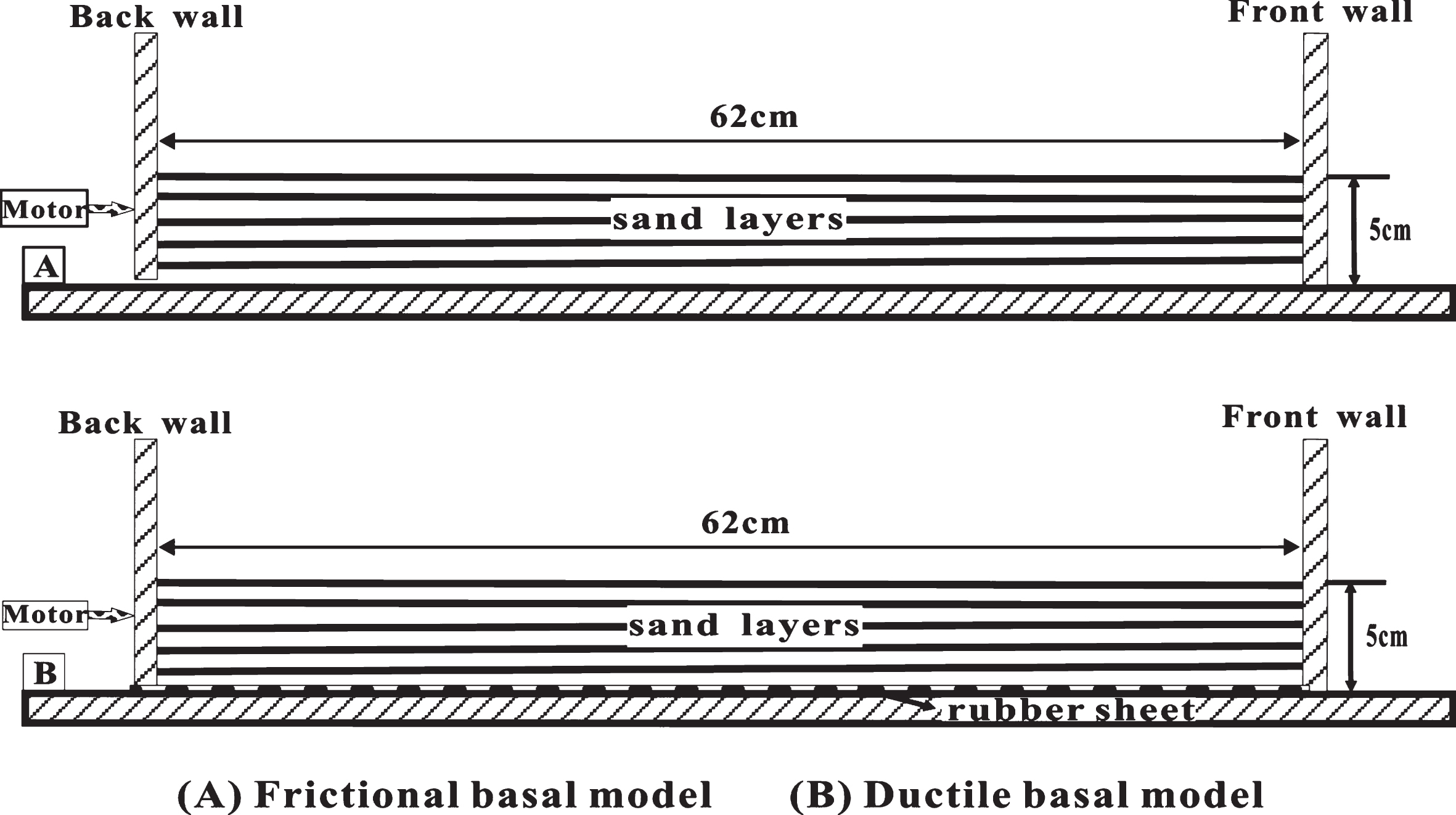
Sketch map of analogue modeling experimental apparatus.
Dry, 0.25–0.3 mm grain size quartz sand, which have an inner frictional angle of 30°–31°, was used to simulate the brittle upper crust. Dry quartz sand has long been recognized as an appropriate analogue material for simulating brittle deformation in the upper crust due to its nearly perfect Mohr–Coulomb behavior [19]. The sand layers are interlaid by thin layers of the same sand colored by black ink. To eliminate the occasional experimental phenomenon, all models were repeated at least thrice and similar results were obtained. Both of the models were compressed with a displacement of 12 cm from left movable wall at a constant displacement velocity of 4.0×10⁻⁶ m/s.
The behavior of the quartz sand in these simulations is described by Mohr-Coulomb plasticity. This model, defines the shear strength of a material as a linear function of the effective normal stress acting on the failure surface: τ f = c + σn tanφ. Where τ f is the shear strength, c is the cohesion, σ n is the effective normal stress on the shear plane, and φ is the friction angle [20].
The basal viscous layers used a transparent silicone polymer (PDMS) with a Newtonian viscous behaviour. It is modelled as a linear viscous material: Γ = 2ηɛ.
Where Γ is the deviatoric stress, η is the viscosity, ɛ is the strain-rate [21].
We configured cm-scale numerical models that eliminate the need for scaling between the analogue and numerical models. As such, the gravity, length, density, shortening rate, angle of internal friction of brittle materials are equal in both analogue and numerical models (Fig. 2).
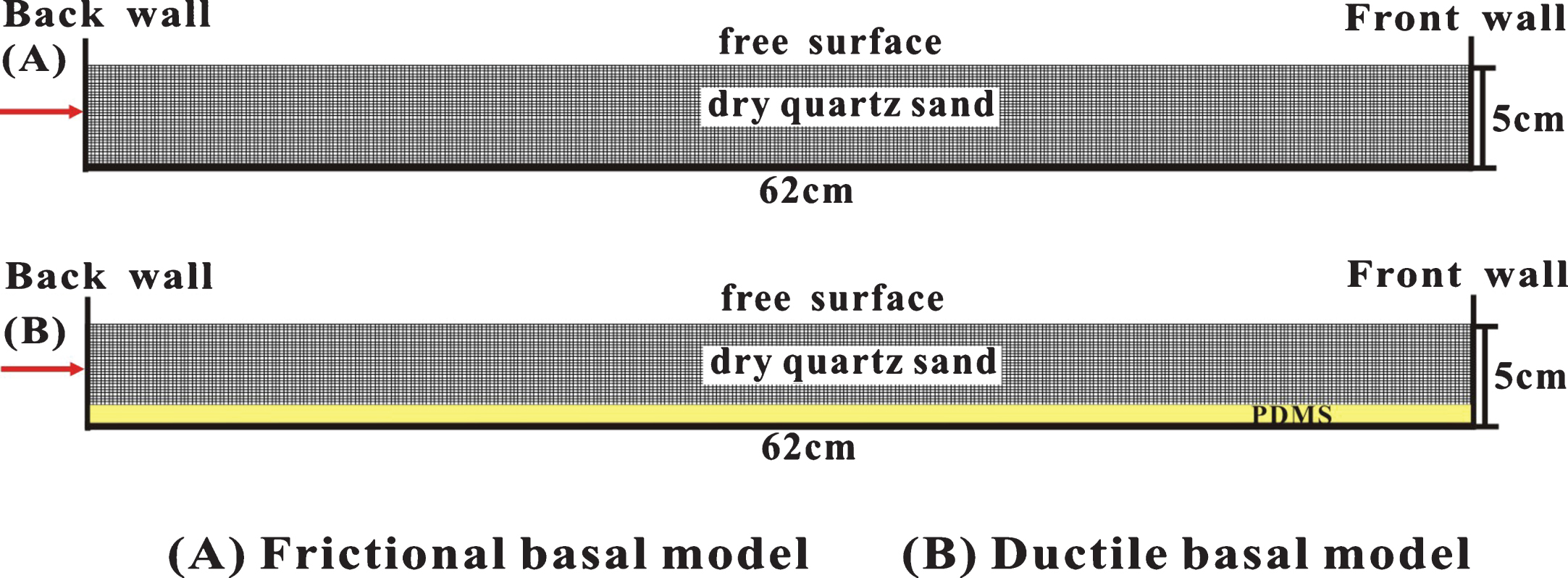
Sketch map of numerical model experimental apparatus.
The quartz sand used in this study has a grain size of 0.30–0.45 mm, a bulk density of 1.43 g/cm3, a coefficient of dynamic stable friction is 0.65 and a coefficient of static stable friction is 0.59. The viscous layer has a density of 0.96 g/cm3 and a viscosity range of 1×10²–1×10⁴ Pa s (see Table 1). The design of the six sets of models respectively change the thickness of sand pack, the thickness of silicone putty décollement, the frictional coefficient of sand pack, the viscosity of silicone putty and mesh resolution (see Table 2).
Material parameters (at cm-scale)
Material parameters (at cm-scale)
Parameters of the numerical models
Note: v is the shortening velocity, Hb is the thickness of sand pack, Hd is the thickness of silicone putty décollement, μ is the frictional coefficient of sand, c is the cohesion of sand, and η is the viscosity of silicone putty.
Frictional experiments
The dynamics of the numerical model are broadly consistent with those of the analogue experiment. During the early stages of shortening, a forward thrusts and a backthrusts first occurred at the front of the back wall. As shortening increased, the number of forward thrust and fault displacement increased. As shortening reached 12 cm, in both of the sets of models, an in-sequence imbricate thrusting wedge of ∼19° taper and 26 cm length formed (Fig. 3).
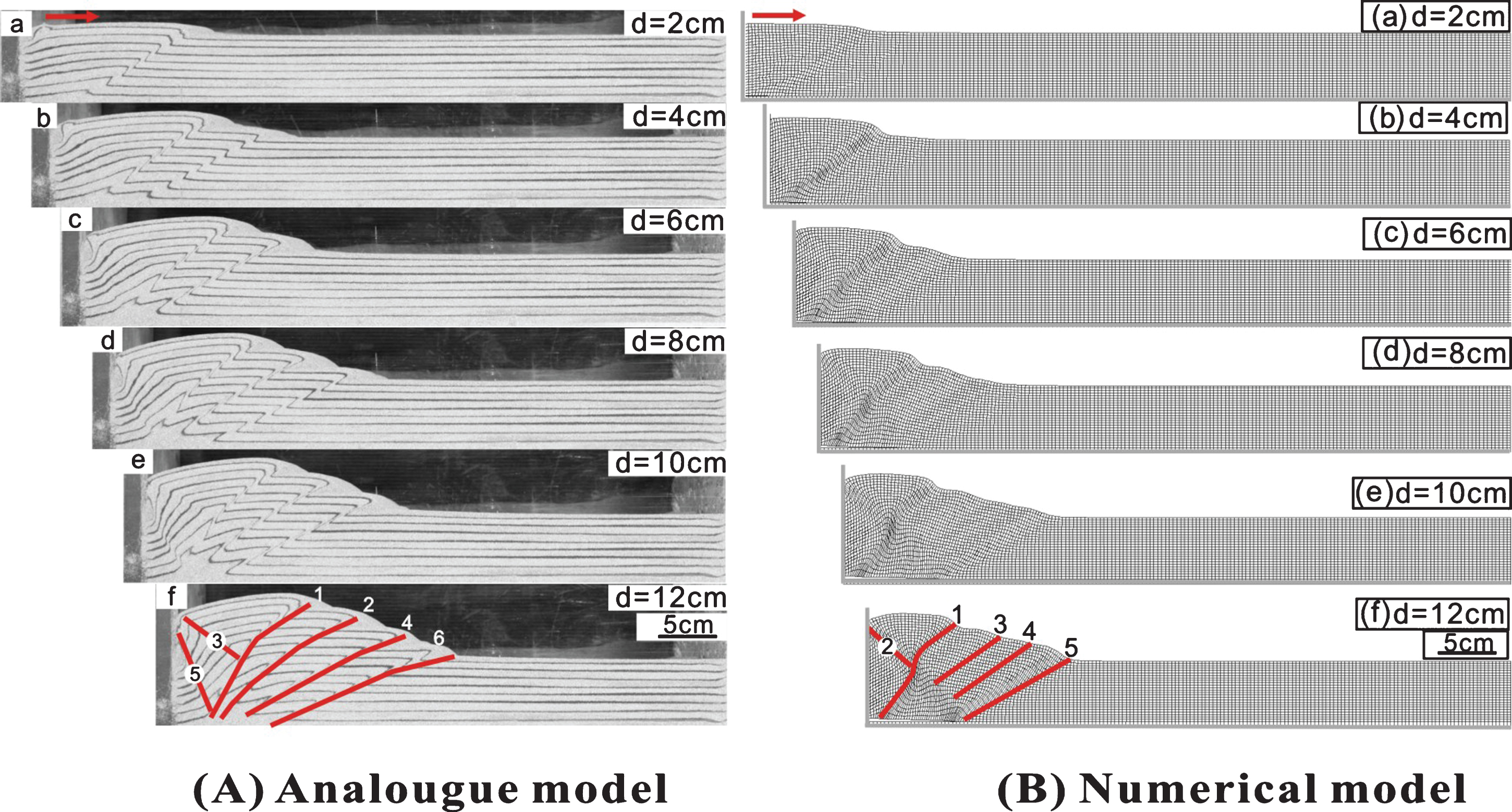
Results for the analogue and numerical frictional experiment.
The dynamics of two ductile basal models are slightly different. In the analogue ductile model (Fig. 4A), a box fold with a frontward vergence first occurred at the front of the back wall. As shortening increased, a series of back thrusts developed almost synchronously at the front of the box fold, forming a thrust wedge with a dominantly backward vergence. However, in the numerical ductile model (Fig. 4B), a steep backthrust first occurred. With continued convergence, it also developed a series of back thrusts. After 12 cm of shortening, the higher-taper forward-vergent thrusting domain of analogue ductile model exhibited a taper of ∼9° (Fig. 4A d), which is distinctly lower than that in the numerical ductile model (Fig. 4B d).

Results for the analogue and numerical ductile basal experiment.
At the beginning of the deformation, forming a set of conjugate fault group at 45° to the extrusion direction on the back wall. The sand layer on the back wall is weakly raised (Fig. 5 b). As shortening increased, a second group of conjugate fault group was developed, the sand layer on the back wall and the front wall as a whole uplift, absorbed the main amount of extrusion deformation (Fig. 5 c). Further shortening formed a large-scale short-line conjugate joint in the center of the model. Its causes may be related to the lateral collapse caused by the gravity of the sand layer. The oblique conjugate fault group is developed at the front wall (Fig. 5 d). After 12 cm of shortening, the deformation pattern does not change much, and the sand layer in the center of the model undergoes the overall uplift (Fig. 5 e). The profile shows symmetrical uplift pattern on both sides of the model.

Experimental result of contractional substrate without the sidewalls.
Type 1: The deformation in all the numerical model with different frictional coefficient initiated with a forward-vergent thrust at the front of movable wall (Fig. 6A). Continued shortening progressively formed drastic different deformation styles. The numbers of box folds apparently increased as the frictional coefficient decreased. However, the speed of deformation propagation generally decreased as the frictional coefficient decreased. The total shortening accommodated by the forethrusts apparently decreased as the frictional coefficient decreased. After 12 cm of shortening, the max shear strain-rate demonstrate that the structural deformation of the second box folds is the most active, when the frictional coefficient are 0.3 and 0.5 (Fig. 6B).

Experimental result of numerical model with different frictional coefficient.
Type 2: By comparing and analyzing the experimental results of different extruding speed digital sandbox, we found that the extrusion rate has little effect on the tectonic pattern and deformation evolution of the fold-thrust belt. The deformation process of each group is basically the same. At the beginning of the extrusion, a rushing structure is formed near the back wall. With the increase of the extrusion amount, a series of forward-forward thrusts are formed in the forward direction. Rapidly uplift of the cap layer near the back wall absorbs most of the shortening. The initial inclination of the pre-thrust formation is about 30°, the experiment is characterized by a pre-developed anticline-thrust-tectonic-shaped fold-thrust wedge (Fig. 7A). The max shear strain-rate demonstrate that the larger speed contributes to the deformation to the foreland (Fig. 7B).
Experimental results of numerical sandbox with different speeds.
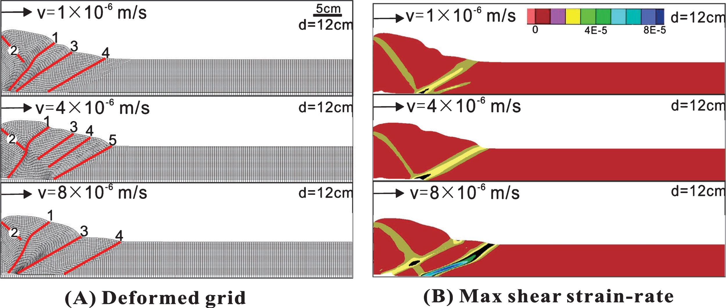
Type 3: Ductile basal experiments of numerical model with different velocity deformation style is similar. After 12 cm of contraction, all of the models resulted in a series of back thrusts with a nearly horizontal overall surface and with a steep frontward vergence at the front of movable Wall (Fig. 8A). The numbers of back thrusts apparently increased as the displacement velocity increased. Meanwhile, the taper of frontward vergence generally increased as the displacement velocity increased. The back thrusts accommodated 25%–56% total shortening, respectively. The max shear strain-rate demonstrate that the most actively structural deformation apparently moved forward as the displacement velocity increased (Fig. 8B).
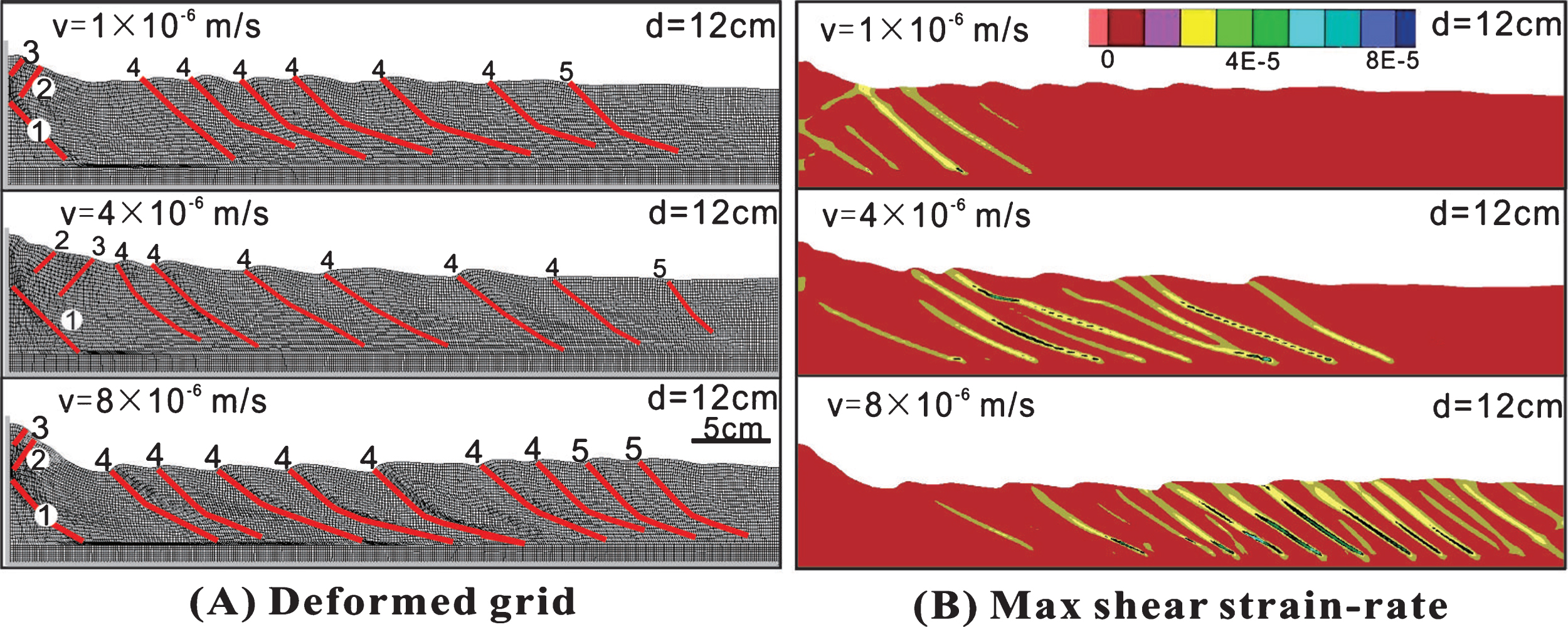
Experimental result of numerical model with different velocity.
Type 4: Results of the different viscosity of PDMS experiments clearly show that different viscosity may result in drastic differences in the structural evolution of fold-and thrust (Fig. 9). Broad and gentle fold-and-thrust belts (dominated equivalently by forethrusts and back thrusts) would formed when the viscosity of weak basal is high(1×10⁴ Pa s). However, The landward-vergent thrust wedges (a series of back thrusts) would formed when the viscosity of weak basal is extremely low (1×10² Pa s and 1×10³ Pa s). In the low viscosity of weak basal experiment, the numbers of back thrusts and the taper of frontward vergence at the front of movable Wall apparently decreased as the viscosity increased. After 12 cm of contraction, the max shear strain-rate demonstrate that the most actively structural deformation apparently differences as the viscosity of weak basal change (Fig. 9B).
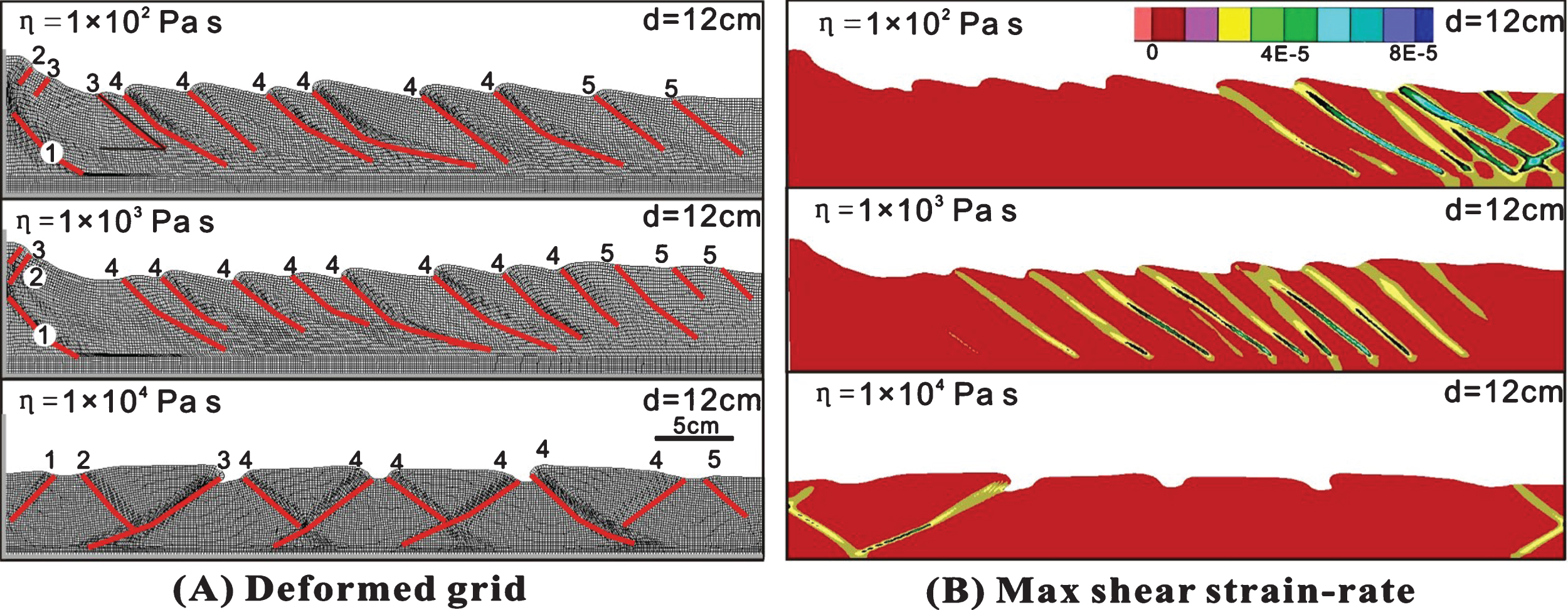
Experimental result of numerical model with different viscosity of PDMS.
Type 5: Different thickness of PDMS lead to different deformation styles (Fig. 10A). The numbers of back thrusts decreased as the thickness increased. However, the numbers of frontward vergence at the front of movable Wall increased. In the model with the lowest thickness of 0.5 cm, produced in-sequence imbricate thrusting in the upside of the back thrusts, formed many small-scale box folds, dissimilar to what was observed in the model of thick (1.0 cm, 2.0 cm). The max shear strain-rate demonstrate that the most actively structural deformation in all of models distributed in the center of the models (Fig. 10B).

Experimental result of numerical model with different thickness of PDMS.
Type 6: Experimental results of different sand cohesion models show that the cohesion of brittle materials has a significant effect on the mathematical simulation experiments. In the case of ductile basal, when the cohesion of the sand is small, the deformation of the fold-thrust zone tends to be gentle, the throws of the back fault is small, the thrust belt width is larger, and the overall uniform uplift of the mesh absorbs the major shortening. When the cohesion value is large, the grid deformation is intense, the development of the back fault is larger, the stress propagation is faster, and obviously developed purely landward-vergent thrusting, accompanied by the development of small pop-up structure (Fig. 11).

Experimental result of numerical model with different sand cohesion.
The forming conditions of Fold-and-thrust wedges
Fold-and-thrust wedges (dominated by imbricated forethrusts) is the most common types of fold-and-thrust belts in nature. It can be well explained by the classic Coulomb wedge theory [22]. This study use analogue and numerical frictional experiments reproduced the formation of fold-and-thrust wedges. In numerical frictional experiment, Low taper fold-and-thrust belts (dominated by sequential box folds) formed, when the basal décollement has a low frictional coefficient (a low shear strength). High taper fold-thrust wedge formed, when the basal décollement has a high frictional coefficient (a high shear strength). Meanwhile, the width of FTB generally increased as the frictional coefficient decreased (Fig. 12). These experimental results combined with the research of previous physical simulation can provide mechanical boundary conditions of fold-thrust wedge formed. The qualitative agreement between analogue and numerical experiments of frictional wedges is encouraging even though discrepancies do exist. Numerical model is idealized two dimensional, so there is no lateral friction, maybe the probable reason. However, Our previous investigations have revealed that lateral friction can strongly influence or even totally dictate the structural evolution of entire models [23].
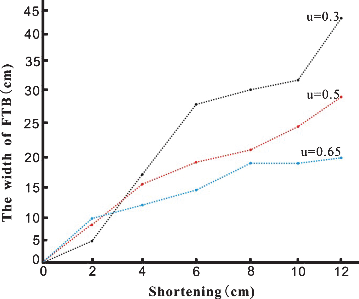
Plot of width of FTB to the frontwall in the numerical model vs. shortening.
Previous studies showed that a weak basal décollement, a seaward-dipping backstop, and a landward-dipping basal décollement have been proposed to be responsible for the origin of landward-vergent thrust wedges in Cascadia [10, 14]. The landward-vergent thrust wedges can only be well reproduced in analogue and numerical models with a weak basal décollement but cannot been reproduced in the presence of a ductile basal décollement indicates that weak or ductile basal décollements maybe an essential factor in determining the origin of landward-vergent thrust wedges.
In the ductile basal experiments of numerical models, the max shear strain-rate demonstrate that the σ1 (the maximum compressive stress) didn’t rotate. Therefore, we can speculate that the reversal of the relative shear direction within the ductile basal décollement may be the result of landward-vergent thrusting. The fact that the broad and gentle fold-and-thrust belts (dominated equivalently by fore thrusts and back thrusts) would formed when the viscosity of weak basal décollement is high. However, The landward-vergent thrust wedges would formed when the viscosity of weak basal décollement is extremely low (Fig. 9). These facts imply that extremely low viscosity of weak basal dé collement due to extremely low shear strength represent an essential factor for the origin of dominantly landward-vergent thrust wedges. The deformation style of Landward-vergent thrust wedge has been less controlled by displacement velocity and thickness of weak basal. It is includes the numbers of back thrusts and fault displacement. Low thickness of weak basal experiment displays complex deformation pattern (Fig. 10A). It is demonstrating that the low thickness of weak basal increased the basal shear stres, then accelerate the deformation of the brittle overburden.
The shear strength of weak basal is τ = ηv/h, where η is the viscosity, v is the displacement velocity, and h is the thickness. The basal décollement in Cascadia exist near-lithostatic pore-fluid pressures [24]. which cause an extremely low shear basal décollement strength in Cascadia, much lower than that in many other fold-and-thrust belts. We therefore speculate that an extremely low viscosity of weak basal décollement are probably the formation conditions of Landward-vergent thrust wedge in Cascadia.
Influence of Lateral friction force on deformation process of landward-vergent thrust wedges
The effect of lateral shear stress on physical simulation can not be completely eliminated and can only be reduced as much as possible [25, 26]. Predecessors mainly use a glass side plate coated with a thin layer of lubricating material or paste a layer of plastic film to reduce the lateral shear stress [27–29].
In the ductile basal physical simulation experiment, the lateral friction has great influence on the deformation of the experimental structure. The presence or absence of lateral frictional forces leads to formed distinctly different structural style. In the presence of sidewalls, Forming a dominantly backward-vergent thrust wedge juxtaposed against a frontward-vergent box fold (Fig. 4). However, in the model without sidewalls, the back thrusts domain did not occur and was replaced by a per-vasively shortened and hence thickened domain (Fig. 5). The experimental results show that the existence of lateral frictional force is a sufficient condition to produce pure post - thrust fault. Mathematical simulation model is idealized two-dimensional model, so there is no role in the lateral boundary. This shows that in some cases, the mathematical simulation experiment is more conducive to the study of tectonic deformation than the physical simulation experiment.
Conclusions
This study through the finite difference method based on numerical simulation experiment illustrates that the high frictional coefficient of substrate due to a strong mechanical boundary conditions is the formation conditions of steep Fold-thrust wedges. An extremely low viscosity of weak basal décollement due to extremely low shear strength are probably key factor responsible for the origin of Landward-vergent thrust wedge in Cascadia. displacement velocity and thickness of weak basal less effect the deformation style of Landward-vergent thrust wedge. As the velocity increased or thickness of weak basal decreased, the number of thrusts and fault displacement decreased. The lateral frictional force has an important effect on the deformation and evolution of the fold - thrust wedge, which is a sufficient condition for the generation of the landward-vergent thrust wedges.
Footnotes
Acknowledgments
We would like to thank anonymous reviewers for their helpful and constructive reviews. Bo Zhang is thanked for assistance in the laboratory and helpful discussions.