
Abstract
Bearing fault diagnosis under variable speed often faces two obstacles: a) blurry time frequency representation (TFR) and thus ambiguous and even unattainable instantaneous frequency (IF) for resampling, and b) complicated and error-prone resampling processes. To address such problems, this paper proposes a new tacholess and resampling-free method for bearing fault diagnosis under variable speed conditions. This method consists of two main steps: a) extract an accurate IF from the vibration data following a dual pre-IF integration strategy and a regional peak search algorithm to search the frequency bins point by point at local frequency regions, and b) with the accurate IF estimator (either shaft IF, instantaneous fault characteristic frequency (IFCF) or their harmonics), multi-demodulate the signal and superpose the resulting frequency spectra of all demodulated signal components using an order peak highlighting method. Then, the instantaneous frequency order (IFO) of signal components of interest contained in the original signal can be highlighted and the IFO spectra can be obtained for bearing fault diagnosis under variable speed conditions. In this manner, the bearing fault can be diagnosed without tachometer devices and resampling procedure. Therefore, the proposed method can substantially reduce human involvement and facilitate its implementation in a fault detection expert system. The effectiveness of the proposed method is validated using both simulated and experimental data.
Keywords
Introduction
The bearing fault diagnosis under unstationary speed operation has long been investigated, for the purpose of preventing severe equipment damage and unscheduled downtime [1, 2]. However, when the rotational speed is time-varying, such speed fluctuations may cause “smearing” of the discrete frequencies in the frequency representation, indicating that these frequencies are no longer easily observable and displayed as discrete frequency lines [3]. As a result, signal processing approaches that are devised for bearing fault diagnosis under a constant speed are ineffective. Therefore, fault diagnosis of bearing under time-varying rotational speed has recently become a new challenge [4–9].
According to the literature [10, 11], shaft IF extraction based on the vibration signal is a crucial pre-processing step for machine fault diagnosis under unstationary operations. To obtain shaft IF, the IFCF is often extracted first. However, the methods used for IFCF extraction, e.g., the instance peak search algorithm, the phase unwrapping technique and the information-fused time frequency (TF) ridge search, are either signal-dependent, computationally complicated or mono-component signal orientated. Therefore, several IF extraction methods have been developed for machine condition monitoring under time-varying speed condition. Combet et al. proposed a method for estimating the instantaneous speed relative fluctuation in a vibration signal based on instantaneous time-scaling factor estimation [12]. Wang et al. [13] adopted the Short Time Fourier Transform-Viterbi algorithm to obtain the IF of distorted signals and then resamples the acoustic signals in time domain for bearing fault detection. Later on, Rodopoulos and Antoniadis predicted the instantaneous fault frequency in rolling element bearings by means of wavelet structure [14]. Such research work has enriched the IF estimation for bearing condition monitoring. Nevertheless, the reported applications of some of those algorithms are limited because of the complicated process, lower accuracy, or expensive computation.
Moreover, the shaft IF-based methods are powerful for gear fault detection under time-varying speed, but they may become less effective for bearing fault detection as the shaft IF is coupled with extracted IFCF by a fault coefficient which cannot be determined without knowing what fault actually exists [15]. Even if the IFCF and shaft IF can be accurately extracted from the vibration signal, the resampling process has to be implemented to convert the time-varying signal in time domain into time-invariant signal in angular domain. To achieve this, a resampling algorithm has to be designed and the selected interpolation algorithm could influence the accuracy of the resampling process [16]. To address such a problem, Shi et al. suggested a resampling-free method via the generalized demodulation (GD) which mapped a curved TF ridge into a straight one paralleling to time axis [17]. However, that method estimated the IFCF based on a pre-processing de-nosing method and the order spectrum was obtained by searching the magnitude corresponding to frequency bins, which complicated the process for on-line detection and was prone to errors for signals with low signal to noise ratio (SNR). If one or more wrong magnitude values were used, the order spectrum would mislead the bearing fault diagnosis result.
To sum up the above, two key issues are to be addressed for developing a simple yet effective method for bearing fault diagnosis under variable speed operation: 1) an efficient IF estimation algorithm, and 2) a more robust fault-related frequency/order peak acquisition method for bearing fault diagnosis. The method proposed in this paper is devoted to solving such key problems. A regional peak search algorithm is firstly developed, based on the conventional peak search algorithm, for fast pre-IF approximation. Subsequently, the integration strategy based on IF synchronization and cumulative probability distribution function (CPDF) is applied to each pre-IF to accurately estimate the IF, paving the way for demodulating the multi-component vibration signal. The IFO spectra can then be automatically obtained by multi-demodulation and spectral superposition for bearing fault diagnosis under an unstable rotating speed condition without relying on tachometers and human intervention.
The paper is organized as follows. Section 2 presents the proposed method for IF estimation and details the auto IFO spectrum creation process. The proposed method is also tested in Section 2 by numerical analysis. The experimental examination is given in Section 3 and the paper is summarized in Section 4.
The proposed automatic IFO extraction method
The automatic IFO extraction method involves two crucial procedures: accurate IF extraction without relying upon any rotating speed measurement devices and IFO acquisition without resampling for bearing fault diagnosis. Hence, the IF estimation based on the integration of two pre-IFs will be elaborated first in this section, paving the way for IFO extraction. Subsequently, the extraction of IFO spectra without human involvement is introduced, from which the fault diagnosis can be implemented for bearing condition monitoring.
Accurate IF estimation via integration of dual pre-IF components
TFR-based IF extraction from vibration signal is a popular way for the case where the tachometer installation is not practical due to the design reasons and cost concerns. Therefore, IF component estimation using TF analysis is adopted for the proposed method. However, the extracted IF from TFR is often of low-accuracy because it is vulnerable to background noise and interfering signal components. Even though the IF can be preciously extracted, the IF category cannot be determined as the dominant signal component of the TFR is unknown. In order to solve these problems encountered in IF estimation, this paper proposes to approximate IF using an integration strategy. Specifically, two dual pre-IF components are first pre-extracted from different frequency bands of the analyzed signal. The two extracted IF component can then be integrated to complement each other, thereby improving the accuracy of the output IF. The pre-IF in this paper is defined as the IF coarsely extracted from signals’ TFRs, which is not the final output of IF. This subsection firstly presents the TF analysis method for signal TFR and the introduction of pre-IF extraction. The integration strategy of the dual pre-IF components is then elaborated.
STFT-based TF analysis
Since short time Fourier transform (STFT) is a powerful tool for time frequency analysis of nonstationary signal, the TFRs in this paper are obtained via STFT. For a signal x(t), its STFT can be defined as
To obtain an acceptable pre-IF estimation based on the STFT-generated TFR, the regional peak search algorithm is introduced in this subsection. The maximum spectrogram of each time bin is randomly varying along with time proceeding for multicomponent signals as a signal component does not keep dominating the TFR, thereby resulting inaccurate and messy pre-IF estimators when using the traditional peak search algorithm. The regional peak search algorithm is, therefore, proposed to address this problem. The proposed algorithm is based on the fact that the shaft rotating speed often exhibits a smooth transformation and does not change dramatically in most industrial cases. The steps of the proposed algorithm are detailed as follows: Pick the frequency at the starting time point with the maximum spectrogram. Search the initial value of the neighbouring frequency corresponding to the maximum spectrogram through the entire frequency band at the current time bin m, which can be formulated as
Evaluate the extracted f (m, k) using the criterion presented in the following
Proceed with the time index m until all time bins are considered, i.e., m equals to the number of windows for STFT.
In this way, the disadvantage (frequency mis-estimation at some time instants) of conventional peak search algorithm can be overcome and, ideally, the pre-IF would be more accurate. However, as shown above, the regional peak search algorithm is dependent on the user-specified parameters α and β, which, inevitably, would affect the accuracy of IF approximation. This drawback will be overcome using the integration strategy elaborated in subsection 2.1.3.
The regional peak search algorithm stated above is devised to obtain a more precise pre-IF estimator. In order to create two pre-IF estimators to further improve the accuracy of output IF, the frequency band of the analyzed signal has to be partitioned to get shaft rotating frequency band
Although the pre-IFs can be extracted from the lower frequency band and resonance frequency band using the STFT-based TF analysis and reginal peak search algorithm, it does not guarantee that both extracted pre-IFs are sufficiently accurate for bearing fault diagnosis. In fact, it is likely that the extracted pre-IFs still suffer from mis-estimation at some time bins due to the noise interfering and non-uniform signal component energy distribution. The extracted pre-IFs are usually complementary, i.e., one pre-IF is mis-estimated at some time instants; while the other pre-IF present erroneous estimation at different time instants. Thus, this paper proposes to integrate the two pre-IFs to make them complement mutually. In this way, the dual pre-IF takes advantage of each other and the accuracy of final estimated IF can be enhanced. The integration strategy consists of three major steps, as detailed in the following.
Step 1: Synchronization of dual pre-IF
Since the extracted pre-IFs are from lower frequency band and resonance frequency band, respectively, it is unlikely that they are of the same type IF (the same type IF here means that both pre-IFs are either shaft speed related IF components or bearing fault related IF components). However, the two pre-IFs are distinguished merely by a coefficient. They can, hence, be synchronized by such a coefficient. The synchronization can be expressed as
Step 2: Abnormal interval localization based on CPDF
Taking the absolute value of the difference between
If the extracted pre-IFs are accurate enough, the difference between f
c
(t) and
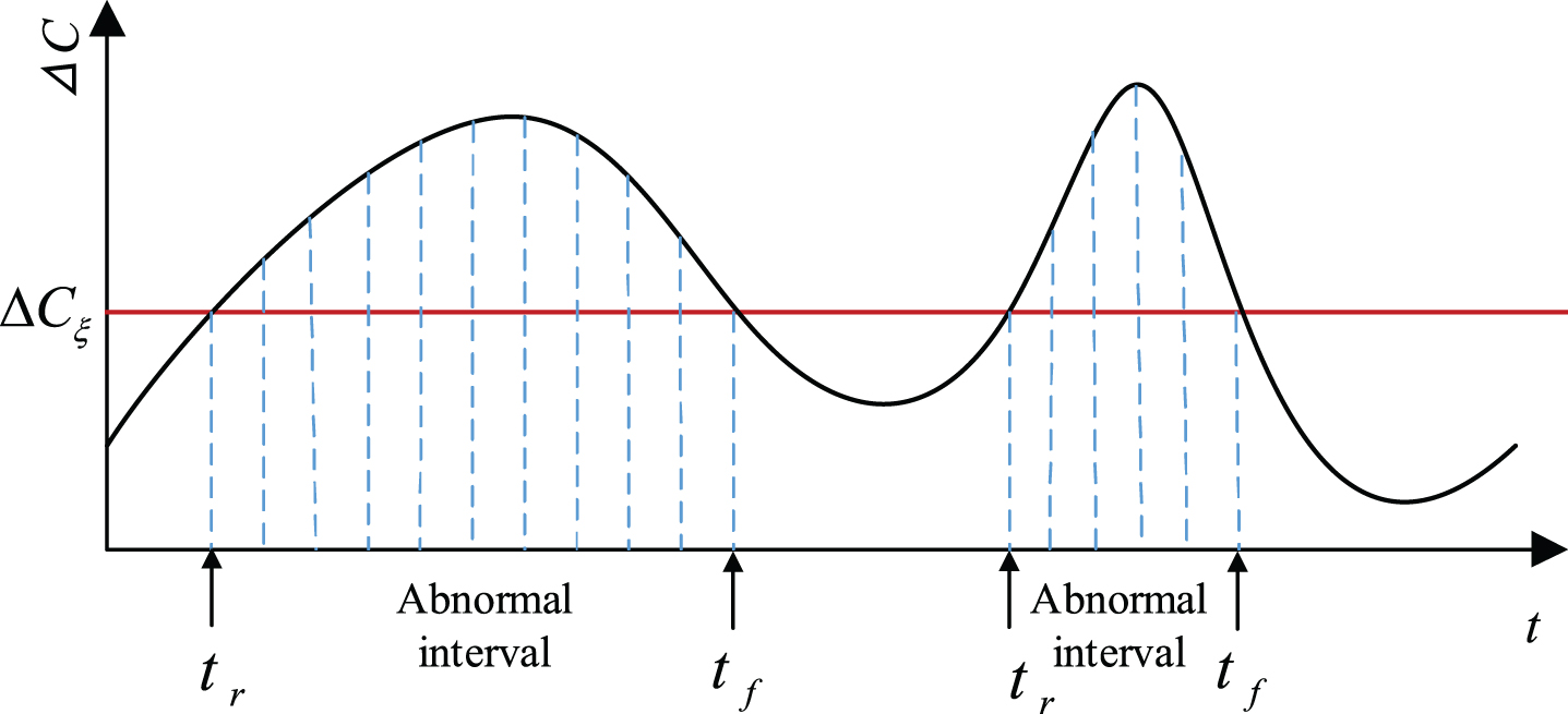
Abnormal interval illustration.
The basic idea of CPDF-based method for threshold determination is that if the extracted pre-IFs are both correct, the difference ΔC (t i ) between the two is always equal to zero or a small value (errors are allowable); otherwise ΔC (t i ) would be greater than the small value, as shown in Fig. 1. The small value is the threshold ΔC ξ , which indicates the presence of abnormal intervals. With the reginal peak search algorithm proposed previously, even though the mis-estimation is inevitable at some time instants, pre-IFs can be mostly extracted correctly; therefore, the cumulative probability P0 of ΔC (t i ) elements that are zeros or within the allowable error (i.e., the threshold ΔC ξ ) make up a large proportion, for instance 50% ∼95% of ΔC. The specific value of P0 has to be determined in the light of the extracted pre-IFs. Generally, the more time instants of pre-IFs present abnormality, the smaller the P0 is. The threshold ΔC ξ corresponds to the determined P0, as shown in Fig. 2. Once the threshold ΔC ξ is decided, the abnormal intervals can be determined. As illustrated in Fig. 1, the two dashed line filled parts are the abnormal intervals.
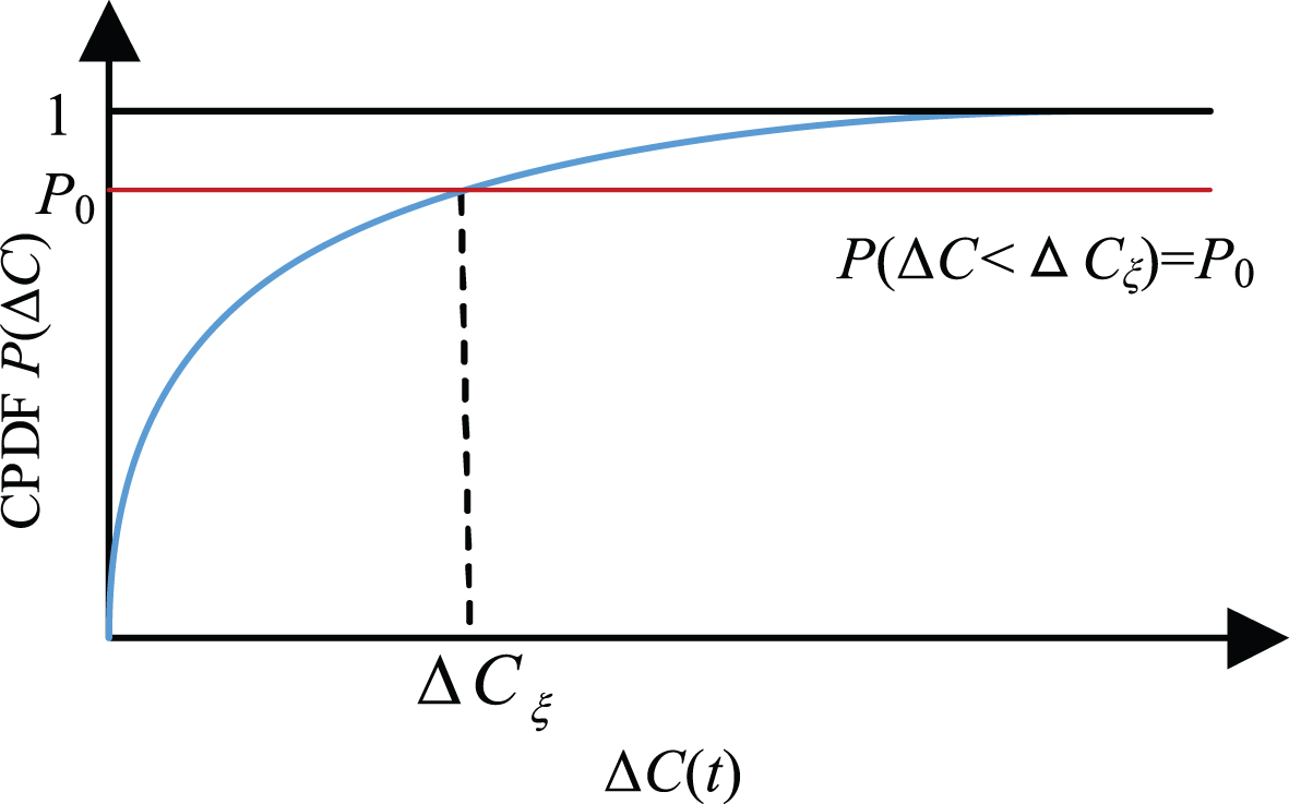
The demonstration for threshold ΔC ξ decision using CPDF.
Step 3: Dual pre-IF integration for abnormal intervals using standard deviation (STD) Rotating machinery is an inertial body and hence the rotating speed would usually not experience abrupt changes. Along this line, the differences between the two pre-IFs can be used as an indicator for integration as well. In terms of located abnormal intervals, the STD of each is calculated as STD is a measure that is used to quantify the amount of variation or dispersion of a set of data values. A low STD indicates that the data points tend to be close to the mean of the dataset, while a high STD indicates that the data points of abnormal intervals are spread out over a wider range of values. Therefore, the integration strategy of abnormal intervals is that a lower STD of data points in abnormal intervals is closer to true IF and hence such data points are selected, while data points of abnormal interval with a higher STD are abandoned. This process can be expressed as
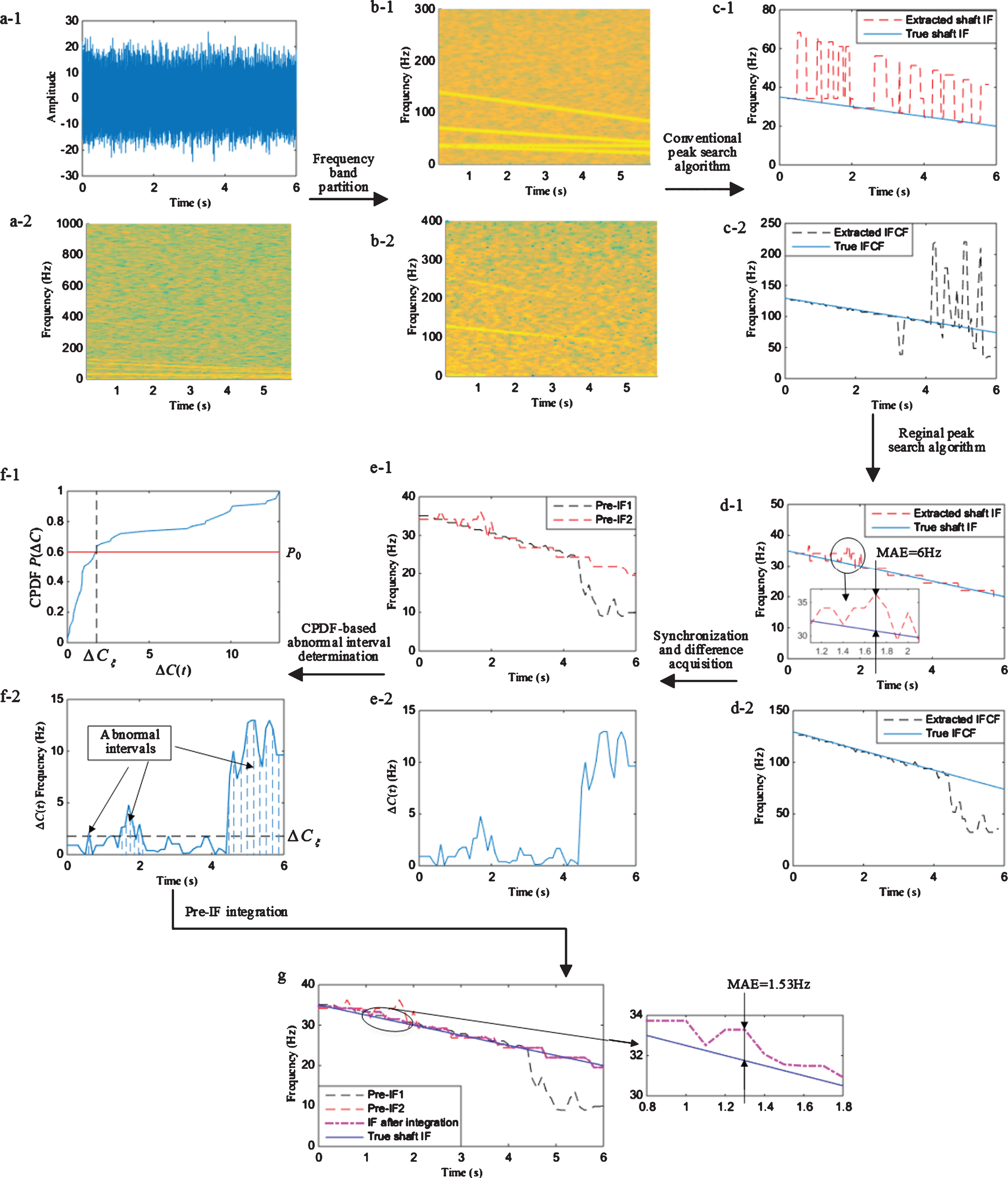
The more accurate IF can then be obtained via the three steps elaborated above. To examine the effectiveness of the proposed integration strategy, a simulated signal, consisting of the bearing fault induced impulses, shaft rotating speed component, background noise and harmonic interfering, is constructed in this subsection. The generation process of impulsive signal of faulty bearing under variable speed operation can be found in [17]. The signal to noise ratio (SNR) of the impulses is – 12 dB. Sampling rate, fault type coefficient λ and shaft IF f r are 20 KHz, 3.7 and f r (t) = -2.5t + 35, respectively. A harmonic interference of frequency 35 Hz is also mixed into the signal.
To cover the fundamental shaft speed IF and a few of its harmonics, the cut-off frequency of lower frequency band is set as 300 Hz. Using the SK algorithm, the resonance frequency band is determined as [1667 2083] Hz, as presented in Fig. 3. Figure 5 (a-1) shows the simulated signal mixture and Fig. 5 (a-2) exhibits the TFR of its envelope signal. The TFR of partitioned lower frequency band signal and resonance frequency band signal are presented in Fig. 5 (b-1) and (b-2), respectively. The conventional peak search algorithm is employed to extract both the shaft rotating speed related IF and bearing fault related IF, as shown in Fig. 5 (c-1) and (c-2), respectively. The true shaft IF and IFCF are also respectively plotted in Fig. 5 (c-1) and (c-2) for comparison. It can be seen that neither IF can be correctly extracted due to the noise and non-uniform energy distribution of signal components. The regional peak search algorithm is then used for pre-IF extraction. As shown in Fig. 5 (d-1) and (d-2), the extracting results have been enhanced. Nevertheless, there is still big deviation between the extracted IF and the true IF. The maximum absolute error (MAE) is 6 Hz appearing at 1.7 s, which can be seen in the zoomed-in part of Fig. 5 (d-1). As for bearing fault related IF, it is clearly displayed in Fig. 5 (d-2) that the pre-IF in the time duration from 4 s to the end cannot be precisely extracted. Then the proposed integration strategy is utilized. The two extracted IFs are firstly synchronized following the introduction in step 1. The sum of absolute values between f
r
(t) and

Resonance frequency band determined by SK algorithm for the simulated signal.

Illustration of the synchronization coefficient k acquisition for simulated data.
Demonstration of the proposed method for IF estimation based on dual pre-IF integration.
The IF is estimated without using any devices, such as tachometers. However, the bearing fault diagnosis cannot be done yet. The traditional method for diagnosis is to resample signals, followed by order spectrum analysis. The application of this method is often hindered by the error-prone resampling process. This section, hence, presents a resampling-free IFO extraction method with the aid of the estimated IF that is extracted from the vibration signal using the method proposed above.
To eliminate the influence arisen from speed fluctuation, the GD is adopted to demodulate the signal. This is due to the property that a curved path in time-frequency distribution can be transformed into a linear path and thereby the energy of the signal for example y (t) = ej2π[f0t+s0(t)] will be concentrated on the power density of the signal y(t) known as |Y (f) |2 and the power can be expressed as
Since bearing fault induced signal is of multicomponent, a number of demodulators are generated by multiplying the extracted IF by different coefficients. For these demodulators which correspond to the IFCF, shaft IF or their harmonics, the energy of the related TF ridges can be concentrated, making the frequency peaks more pronounced on the frequency spectra. If demodulators are related to none of the IFCF, shaft IF and their harmonics, then no obvious time-frequency components are demodulated by these phase functions. Therefore, no line paths can be found in the time-frequency plane after GD application. Then all resulting spectra of demodulated signal components are superposed and divided by the constant frequency f0 of the estimated IF to obtain the IFO spectrum, from which order peaks associated with the shaft rotating related signal component and fault induced signal components can be observable.
As the signal is divided into lower frequency band and resonance frequency band, we implement the multi-demodulation and spectrum superposition for both of them. In such a way, the fault existence and fault type can then be determined by observing the IFO spectra without human involvement. The resulting spectra of lower frequency band signal and resonance frequency band signal are plotted in Fig. 6 (a) and (b), respectively. From Fig. 6 (b), it can be seen that the extracted IF is the shaft rotating frequency, rather than its harmonics or bearing fault related IFs. In Fig. 6 (a), the orders corresponding to the pre-set coefficient λ and its second harmonic can be clearly recognized. Combining Fig. 6 (a) and (b), it can be concluded that the bearing is defective and the fault type can also be diagnosed.
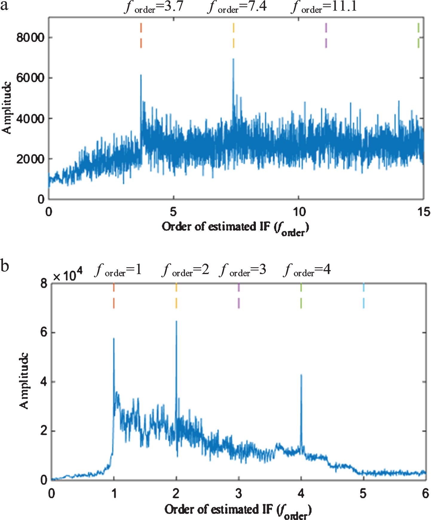
Resulting IFO spectra of simulated signal: (a) the IFO spectrum of resonance frequency band signal, and (b) the IFO spectrum of lower frequency band signal.
To test the diagnosis performance of the proposed method for real cases, experiments are carried out on a SpectraQuest Machinery fault simulator (MKF-PK5M) in the lab of the University of Ottawa. The experiments for bearing outer race fault and inner race fault diagnosis are both conducted.
Inner race fault diagnosis
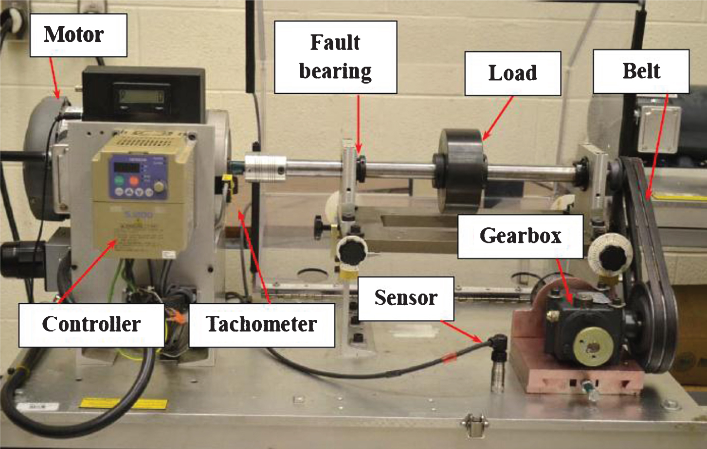
The test rig for inner race fault is displayed in Fig. 7, showing that the shaft is driven by a motor controlled by an AC inverter and there are two ER16K bearings mounted to support the 1-inch steel shaft and the load of 5.03 kg. The faulty bearing is located at the left side. Tachometer and accelerometer are mounted on the test rig to collect the shaft speed (for comparison purpose) and vibration signal, respectively. The data are fed to an NI data Acquisition Module (NI USB-6212 BNC) and recorded by the computer with LabVIEW.

Experimental setup.
Table 1 lists the parameters of the bearings used in the experiment. In the test, the shaft rotational speed first increases from 17 Hz to 33.3 Hz and then drops down to 23.8 Hz during a time period of 17.9 s. The sampling frequency is 12 KHz.
Parameters of the bearings used in the test
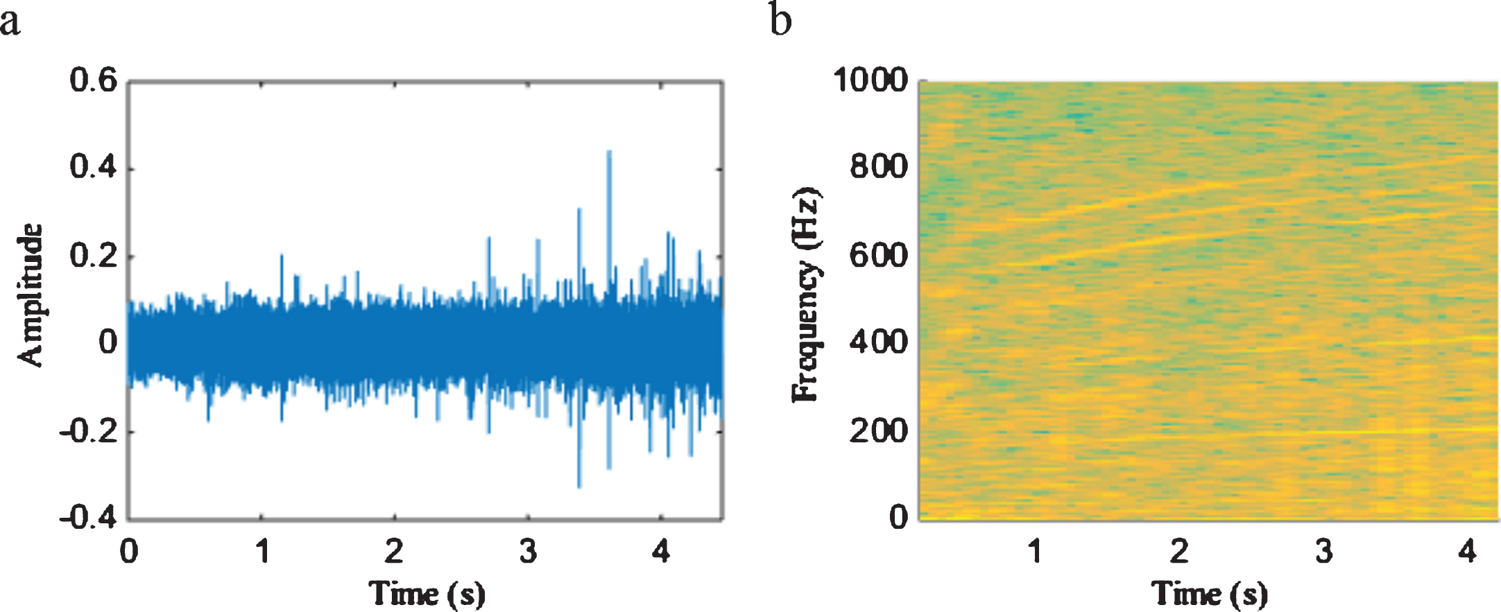
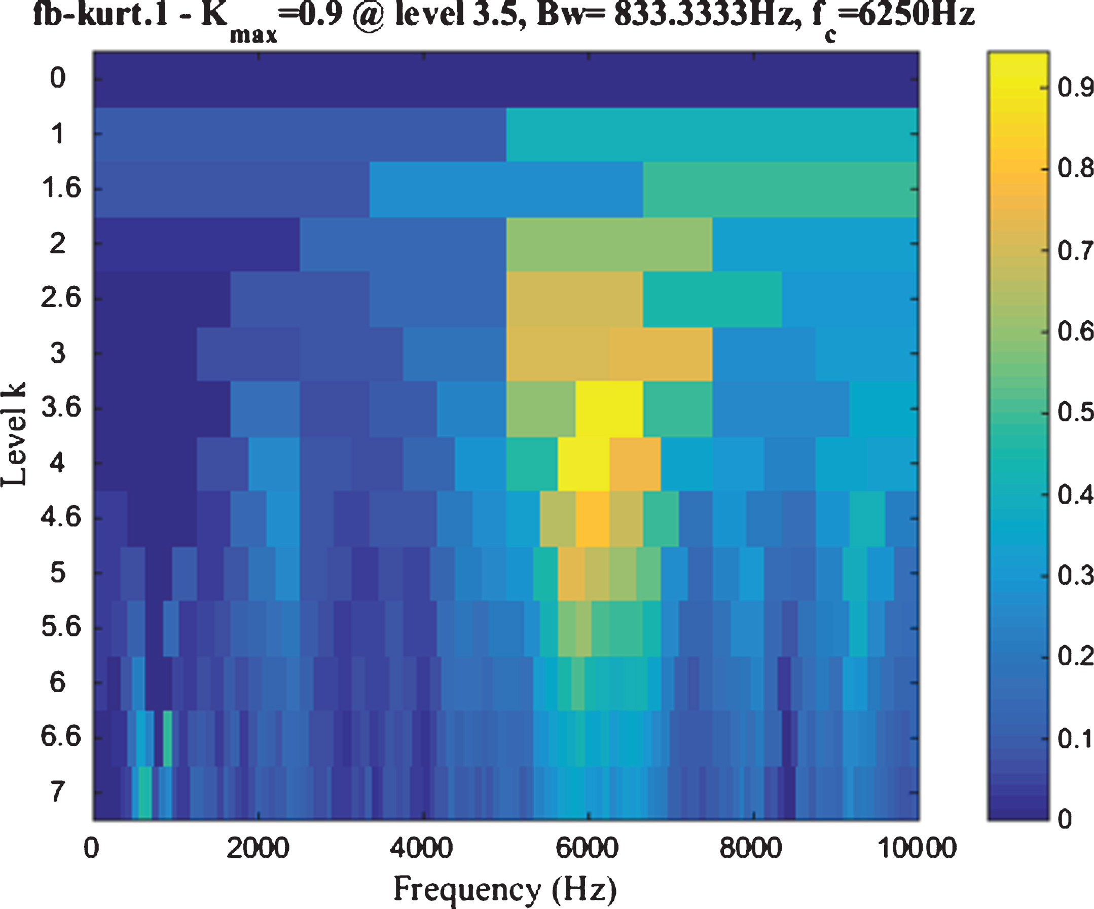
The raw vibration signal and the TFR of its envelope are shown in Fig. 8 (a) and (b), respectively. As seen, Fig. 8 (b) does not present a clear TFR pattern related to the IFCF, shaft IF or their harmonics. Even if the IFCF trend can be easily recognized on the TFR, the fault types cannot be distinguished yet. The vibration signal is then processed by the proposed method. The cut-off frequency of lower frequency band is set as 300 Hz, which is generally sufficient to cover shaft rotating frequency and several its harmonics. The resonance frequency band is determined as [4000 6000] Hz via the SK algorithm, as presented in Fig. 9. The TF analysis is then used, yielding TFR of the lower frequency band signal and the envelope of the resonance frequency band signal shown in Fig. 11 (a-1) and (a-2), respectively. With the proposed regional peak search algorithm, the shaft speed related IF and bearing fault related IF (i.e., IFCF) are plotted in Fig. 11 (b). The real shaft IF measured by a tachometer is also plotted in Fig. 11 (b-1) for comparison. As seen, the extracted shaft IF at a few of time instants deviates from the trend of true shaft IF and do not form an accurate IF pattern. The same can be said for the extracted bearing fault related IF displayed in Fig. 11 (b-2).
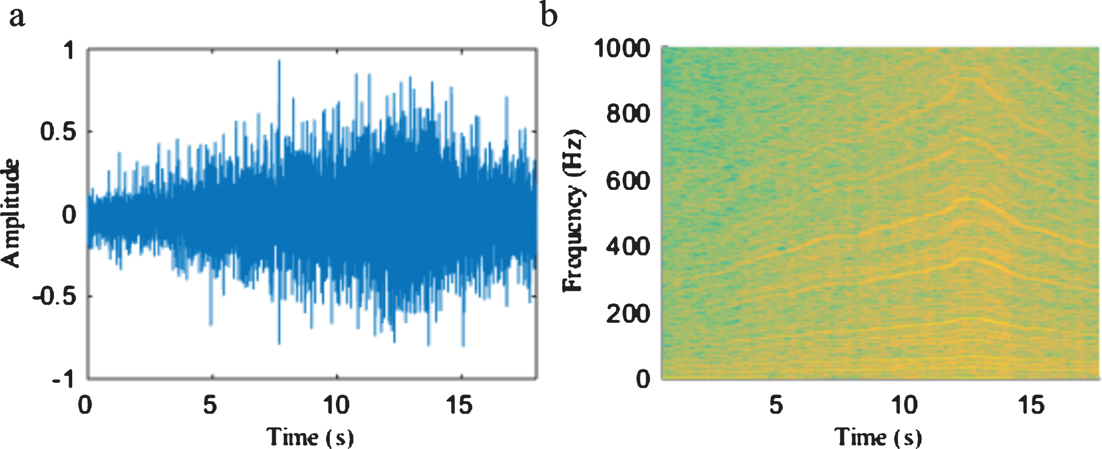
Original signal and TF analysis: (a) vibration signal collected from the bearing with inner race fault, (b) TFR of envelope of the signal in (a).
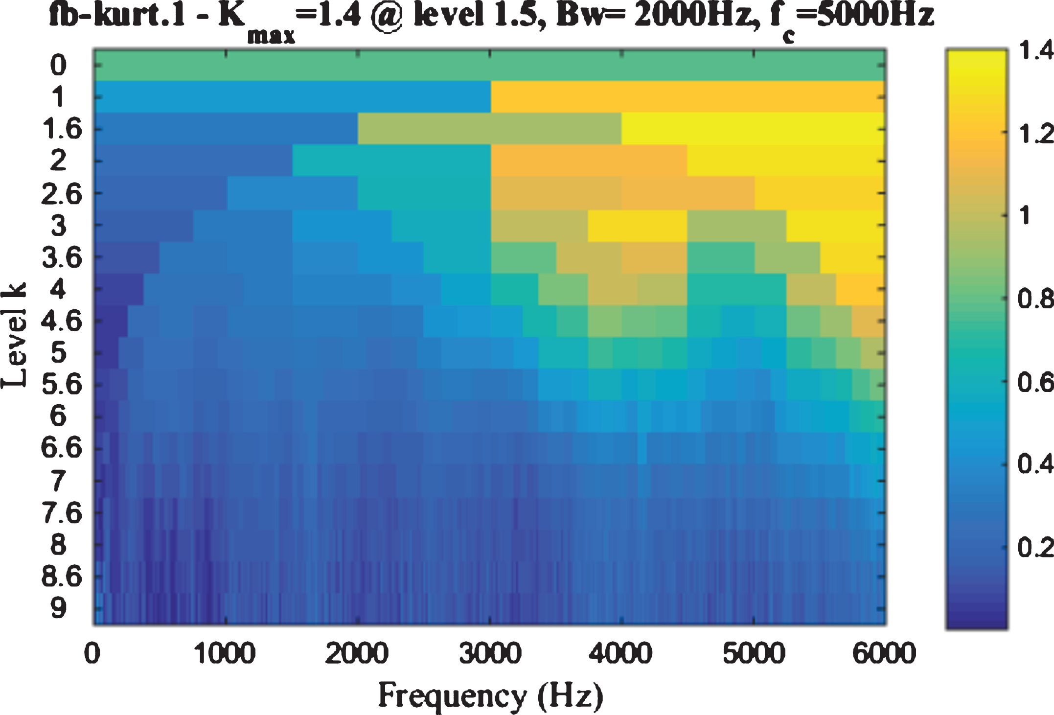
Resonance frequency band determined by SK algorithm for bearing inner race fault signal.
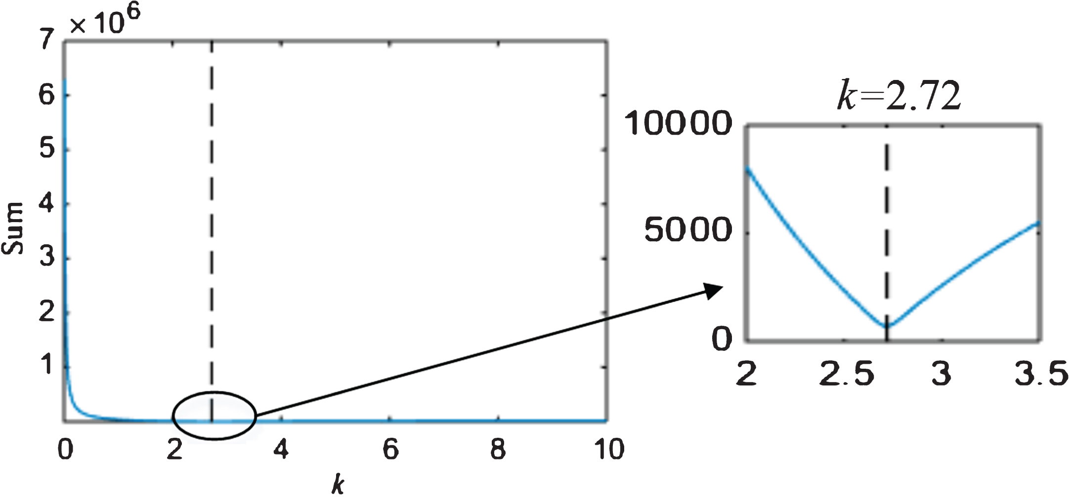
Illustration of the synchronization coefficient k acquisition for experimental data collected from bearing with an inner race fault.
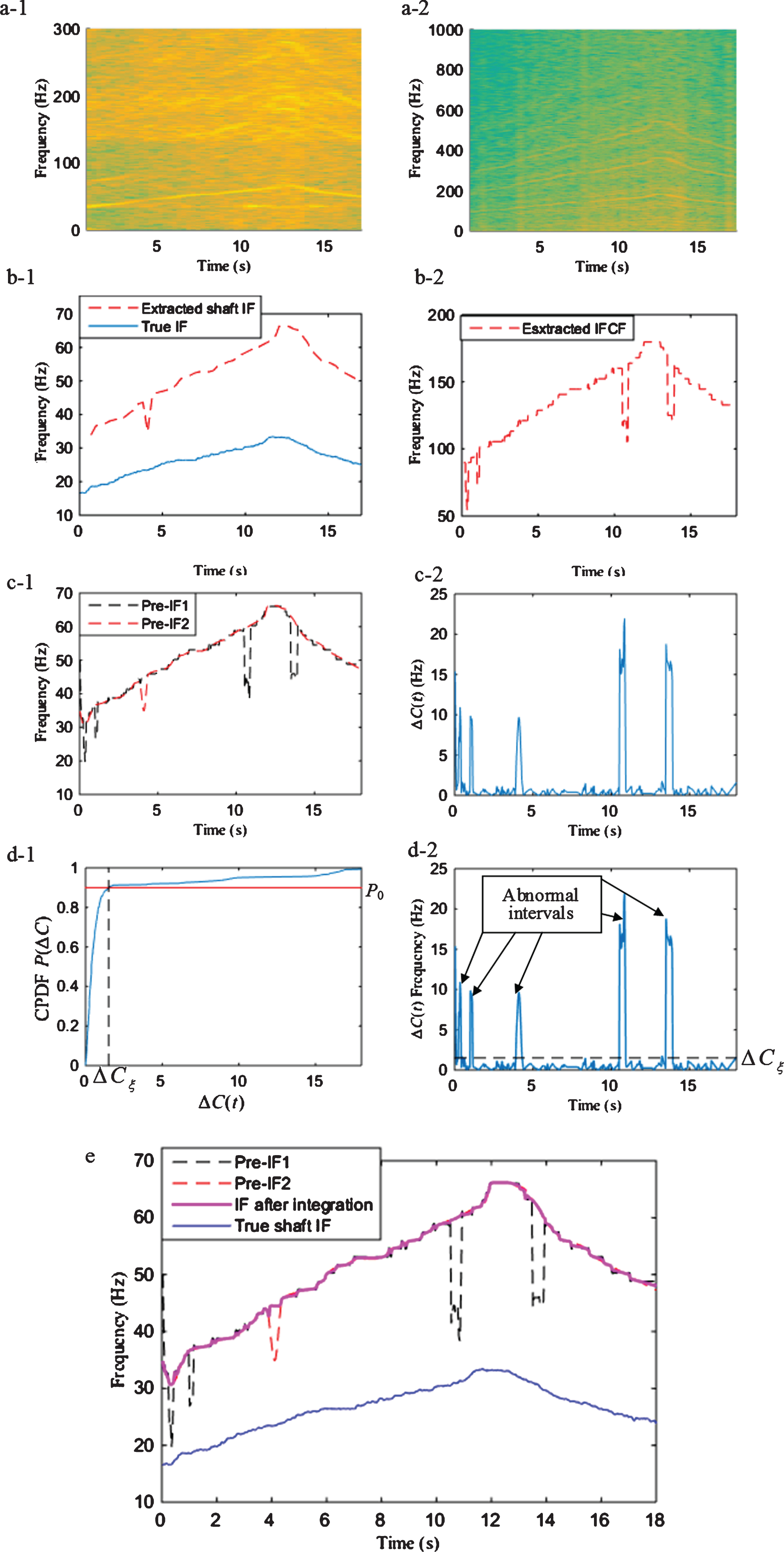
Bearing inner race fault detection using the proposed method: (a-1) TFR of lower frequency band signal, (a-2) TFR of resonance frequency band signal, (b-1) extracted shaft IF based on (a-1) and true IF, (b-2) extracted IF based on (a-2), (c-1) dual pre-IFs obtained by synchronization, (c-2) the difference between the two pre-IFs, (d-1) CPDF for threshold determination, (d-2) abnormal interval extraction, and (e) the IF after integration (dual pre-IF and true IF are also presented for comparison).
To further improve the accuracy of IF estimator, the integration strategy is employed. The synchronization is carried out for the two extracted IF components, resulting dual pre-IF exhibited in Fig. 11 (c-1) (i.e., pre-IF1 and pre-IF2). From Fig. 10, the synchronization coefficient can be found as 2.72 corresponding to the minimum sum of the absolute values between two pre-IFs. It is found that the synchronization coefficient is not identical to the fault characteristic coefficient 5.43, as shown in Table 1. Instead, it is close to a half of 5.43, indicating that the extracted shaft speed related IF is actually its second harmonic, instead of the fundamental one. Figure 11 (c-2) shows the difference between the two pre-IFs after synchronization. Following step 2 and step 3 in subsection 2.1.3, the threshold determination and abnormal interval extraction are exhibited in Fig. 11 (d-1) and (d-2), separately. The threshold ΔC ξ is determined as 1.5095 by selecting P0 as 0.9 for the inner race fault data. The more accurate IF estimation after integration can then be obtained in Fig. 11 (e), which is plotted in the magenta dashed line. For comparison, the pre-IF1, pre-IF2 and true shaft IF also displayed in Fig. 11 (e). It can be observed that the large deviations of pre-IFs can be eliminated by integration. The MAE (= |IF/ - 2 - IF true |) is 1.3 Hz, appearing at t = 0.35 s. The IF and IF true here stand for final extracted IF and true shaft IF, respectively. The IF with higher accuracy is resulted from the integration strategy and then the fundamental phase demodulator of the signal can be accordingly calculated.
As the vibration signal is of multicomponent and the IFs of their signal components follow the same changing pattern but differ by multipliers, it can be demodulated by the fundamental phase demodulator and other demodulators obtained by multiplying the fundamental one by various coefficients. In this way, both the lower frequency band signal and resonance frequency band signal are multi-demodulated by different phase demodulators. Spectrum analysis of these demodulated signals leads to a number of frequency representations. The number of frequency representations is identical to the number of demodulators. The summation of such spectra are then executed to generate the overall frequency representation followed by dividing the frequency by f0 (f0 is the starting frequency at t = 0 of the fundamental demodulator). The IFO spectrum is then automatically revealed without resampling operation and human intervention, as displayed in Fig. 12.
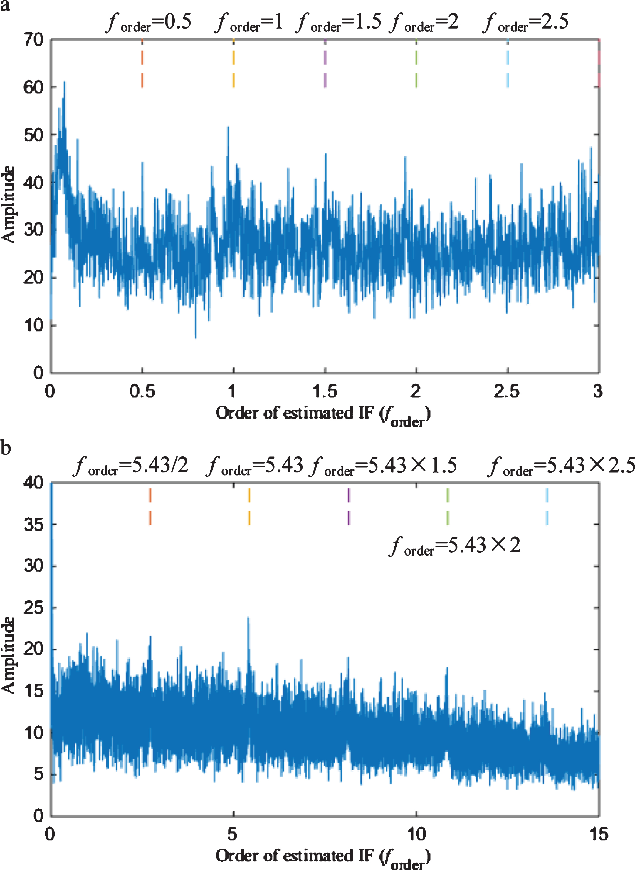
Resulting IFO spectra of the experimental data measured from the bearing with inner race fault: (a) the IFO spectrum of lower frequency band signal, and (b) the IFO spectrum of resonance frequency band signal.
Figure 12 (a) displays the IFO spectrum of lower frequency band signal, in which the order peak can be found at forder equaling 0.5, 1, 1.5 and 2. It can then be confirmed that the extracted pre-IF1 is the second harmonic of the shaft speed related IF. This conclusion is useful for the later bearing fault type classification. The IFO spectrum of resonance frequency band signal is given in Fig. 12 (b). As seen in the figure, it can easily identify order peaks located at forder equal to 2.715 (= 5.43/2), 5.43, 8.145 (= 5.43×1.5), 10.86 (= 5.43×2) and 13.58 (= 5.43×2.5). Therefore, it can be concluded that the bearing is defective and the localized fault is on the inner race of the bearing. The above analyses indicate that the IF can be accurately extracted from the vibration signal and IFO spectrum can be obtained without human intervention. The fault diagnosis decision can be made based on the resulting IFO spectra. It is worth pointing out that no matter the extracted IF is the shaft speed related IF, bearing fault related IF or their harmonics, the diagnosis can be done with confidence as IFO spectra of both speed related signal component and resonance frequency band component are created in the proposed method.
To further test the proposed method, the other experiment, where the bearing has an outer race fault, is performed on the same test bench. The experimental setup is shown in Fig. 13. Two ER16K bearings are used to support the shaft of 1 inch in diameter. A mass of 5.03 kg is mounted on the shaft as an external load. The bearing shaft is driven by an AC converter controlled motor through a coupling. The right side is connected to the gearbox shaft by belts and two sheaves (the smaller one is fixed on the bearing shaft and the larger one is installed on the gearbox shaft). A tachometer is positioned close to the bearing shaft to measure its instantaneous rotational speed. The detailed parameters of the bearing are the same as those listed in Table 1. During the test, the motor shaft rotational speed rises from 30.25 Hz to 60.5 Hz following a nonlinear manner. The sampling frequency is 20 000 Hz.
Experimental setup for vibration data collection from the bearing with outer race fault.
The original signal is shown in Fig. 14 (a) and the TFR of its envelope signal is displayed in Fig. 14 (b). Diagnosis results of the proposed method are presented in Fig. 17. Similar to inner race fault diagnosis, the IF is firstly predicted using the proposed integration strategy and then the multi-demodulation is implemented to obtain the IFO spectrum. The lower frequency band is cut off at 300 Hz again and from Fig. 15 the resonance frequency band determined by SK can be found as [5833, 6667] Hz. The cumulative probability of P0 (ΔC < ΔC ξ ) is also set as 0.9 and therefore the threshold ΔC ξ of the outer race fault case is 3.28 from Fig. 17 (d-1). The synchronization coefficient k is selected as 1.73, as illustrated in Fig. 16. The detailed procedures are plotted in Fig. 17 (a-d). Since the analysis process is similar to those applied to the simulated signal and vibration data from inner race fault, it will not be elaborated for the outer race fault case. The resulting IFO spectra of shaft speed related signal and bearing fault induced signal are displayed in Fig. 18 for bearing fault diagnosis. As observed in Fig. 18 (a), order peaks are found at forder = 0.5, 1 and 1.5, indicating that the extracted IF is the second harmonic of the shaft rotating IF. Thus, the order peaks in the IFO spectrum of bearing fault induced signal at 1.725(= 3.45/2), 3.45, 5.715(= 3.45×1.5), 6.9(= 3.45×2), etc. should be discerned. By observing Fig. 18 (b), such order peaks can be clearly recognized, which validates the effectiveness of the proposed method for bearing outer race fault diagnosis.
Original signal and TF analysis: (a) vibration signal collected from the bearing with outer race fault, (b) TFR of envelope of the signal in (a).
Resonance frequency band determined by SK algorithm for bearing outer race fault signal.
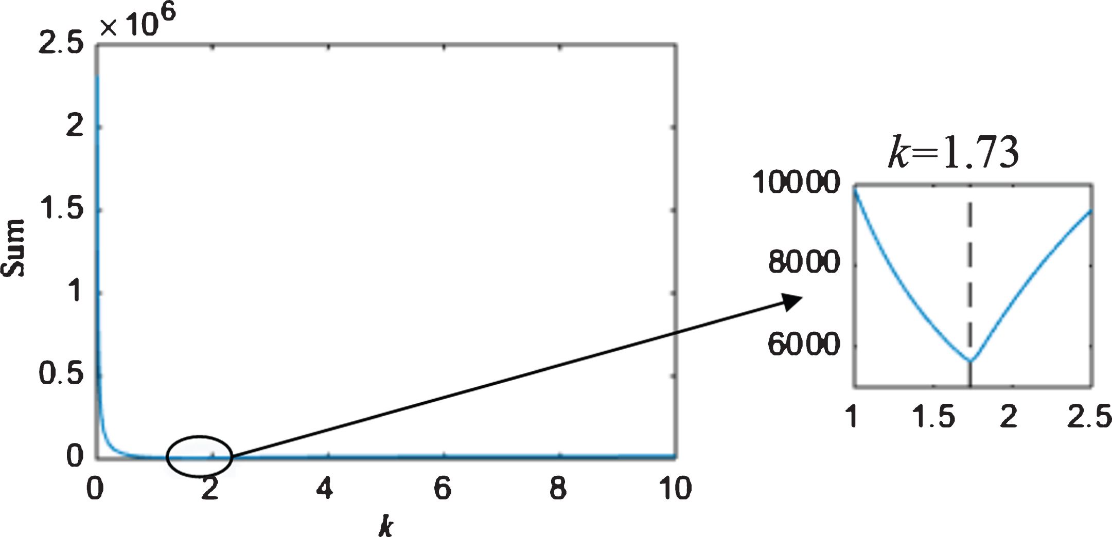
Determination of the synchronization coefficient k for experimental data collected from the bearing with an outer race fault.
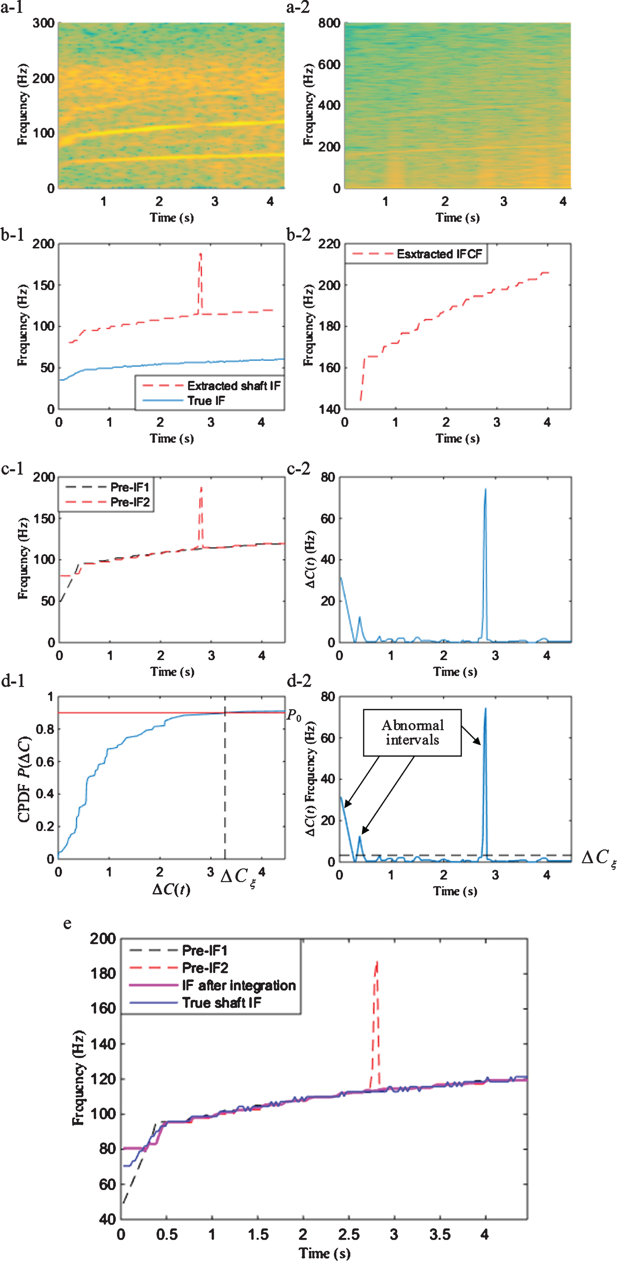
Proposed method for bearing outer race fault diagnosis: (a-1) TFR of lower frequency band signal, (a-2) TFR of resonance frequency band signal, (b-1) extracted shaft IF based on (a-1) and true IF, (b-2) extracted IF based on (a-2), (c-1) dual pre-IFs obtained by synchronization, (c-2) the difference between the two pre-IFs, (d-1) CPDF for threshold determination, (d-2) abnormal interval extraction, and (e) the IF after integration (dual pre-IF and true IF are also presented for comparison).
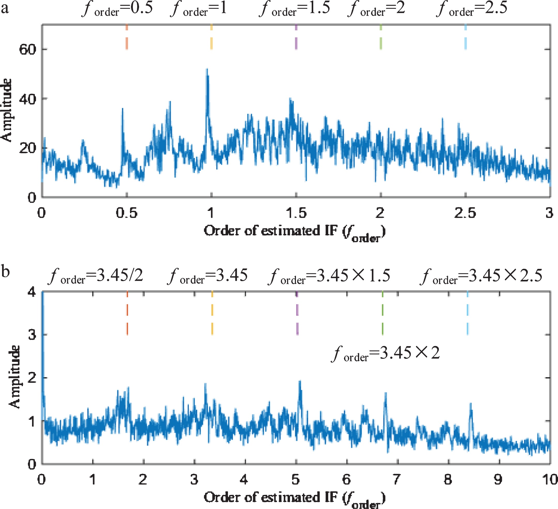
Resulting IFO spectra of experimental data measured from the bearing with outer race fault: (a) the IFO spectrum of lower frequency band signal, and (b) the IFO spectrum of resonance frequency band signal.
A method for bearing fault diagnosis under variable speed conditions without relying on tachometers and resampling is developed in this paper. Two major parts constituting the proposed approach are the integration based accurate IF estimation and the multi-demodulation based order peak highlighting method. The former contributes to the tachometer-free feature of the proposed method and the latter eliminates the resampling step, enabling automatic generation of the IFO spectra and thus making the proposed method more efficient. The IFO spectrum acquisition free from external speed measuring devices and human participation can then be used for bearing condition monitoring under unstationary speed operations. It is also worth mentioning that the estimated IF, which is often not the IFCF, will be identified as shaft IF, IFCF or their harmonics. The diagnosis process based on IFO spectra would not be affected by the type of the extracted IF as the IFO spectra of both shaft speed related signal component and bearing fault induced signal component can be simultaneously created. The effectiveness of the proposed technique is tested using both simulated and experimental data.
Footnotes
Acknowledgments
This work is supported in part by the National Natural Sciences Foundation of China (51605319, 51705349), Jiangsu Province Natural Science Foundation (BK20160318) and Natural Science Fund for Colleges and Universities in Jiangsu Province (16KJB460020). Their supports are very much appreciated. The authors would also like to thank the Lab E026 at the University of Ottawa for the experimental data.