
Abstract
Bearings are essential parts in mechanical transmission systems, and their running states directly affect the reliability and stability of the systems. Therefore, an efficient diagnosis method is necessary to detect faults in bearings. In the present, a simulation model based fault diagnosis method for bears is proposed by combination of finite element method (FEM), wavelet packet transform (WPT) and support vector machine (SVM). In this method, firstly, the agreeable finite element models to simulate faulty bearings are presented to obtain the vibration response signals. Secondly, the vibration signals are decomposed into eight signal components using WPT. Ten time-domain feature parameters of all the signal components are calculated to generate the training samples to train the SVM. Finally, the eight signal components decomposed by WPT from the measured vibration signal in a bear, which are serve as a test sample into the trained SVM, and the work condition of the bearing can be determined. Experimental investigations are performed to verify the effectiveness of the present method. The classification accuracy rates for four type faults, i.e., inner race fault, rolling body fault, outer race fault and the combination of rolling body and outer race faults, are 79%, 81%, 71% and 76%, respectively.
Introduction
The running state of rotating machinery directly affects the performance of the entire machine, including reliability and stability. Thus, fault diagnosis in rotating machinery is a hot topic in the past several decades, and numerous fault detection methods [1–6] and criteria [7–9] were proposed. For the fault detection of bearings, various researchers have reported many methods. Wang et al. [10] gave a good review to the development of a spectral kurtosis method to detect faults in rotating machines. Masmoudi et al. [11] developed a single point bearing fault diagnosis method using simplified frequency model. Do and Nguyen [12] presented an adaptive empirical mode decomposition (EMD) method for bearing fault detection. Tian et al. [13] proposed a motor bearing fault detection method using spectral kurtosis-based feature extraction coupled with K-nearest neighbor distance analysis. Xiang et al. [14] developed a novel personalized diagnosis methodology using numerical simulation and an intelligent method to detect faults in a shaft. Guo and Deng [15] presented an improved EMD method using the multi-objective optimization to extract fault features in faulty rolling bearing. Liu et al. [16] proposed an adaptive stochastic resonance in a new nonlinear system to improve the bearing fault diagnosis efficiency. Shao et al. [17] presented a novel deep autoencoder feature learning method for rotating machinery fault diagnosis. Li et al. [18] developed a Bayesian approach to consequent parameter estimation in probabilistic fuzzy systems to classify bearing faults.
Because the vibration signals carry dynamic information corresponding to different faults about the machine state, mechanical fault diagnosis depends largely on the features extraction methods to extract fault features [19]. As a signal processing tool, WPT [20, 21] decomposes the original signal into multi-layers, and the same frequency bandwidth is offered in each layer. Then, time-domain feature parameters, such as standard deviation, peak, skewness, kurtosis, root mean square, peak factor, clearance factor, shape factor, impulse factor and kurtosis factor, which can be calculated and served as training samples for classification methods, such support vector machine (SVM), deep neural network (DNN), Genetic algorithms (GAs), etc. SVM is a pattern recognition approach, which has been widely used in fault classification [22]. However, it has greatly limited the fault classification using SVM in real-world applications because of the lack of faulty training samples collected from the real-world running machines. Numerical simulations provide a possible way to simply obtain the fault samples for every type of faults under the complex running conditions. Obviously, it is necessary to build up agreeable numerical simulation models to simulate real-world running machines.
For the above reasons, a simulation model based fault diagnosis method is proposed using FEM and SVR to detect faults in bearings.
The simulation model based fault diagnosis method
The basic idea for the simulation model based fault diagnosis method is given. Figure 1 shows the flowchart of the proposed fault diagnosis method.
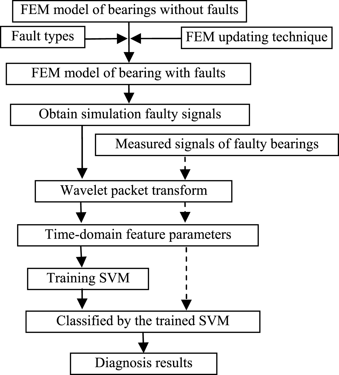
The flowchart of the proposed fault diagnosis method.
Firstly, the agreeable finite element models to simulate faulty bearings are presented to obtain the vibration response signals. The explicit sub-steps are: Built up FEM model of bearings without faults. Insert fault types in the components of bearings. Apply FEM updating technique if necessary. Obtain FEM model of bearing with faults. Obtain simulation faulty signals.
Secondly, the vibration signals are decomposed into eight signal components using WPT. Ten time-domain feature parameters of all the signal components are calculated to generate the training samples to train the SVM. The explicit sub-steps are: Decompose the simulation faulty signals using WPT at level j = 3 to get eight signal components. Ten time-domain feature parameters, as shown in Table 1 are calculated (eight signal components) to generate the training samples to train SVM. Obtain the trained SVM.
Ten time-domain feature parameters
x is the data; N is the number of data points; x m is the mean value of x.
Finally, the eight signal components decomposed by WPT from the measured vibration signal in a bear, which are serve as a test sample into the trained SVM, and the work condition of the bearing can be determined. The explicit sub-steps are: Obtain the measured signals of faulty bearings in real-world running machines. The similar procedures (dotted arrow, as shown in Fig. 1) are performed to the measured signals to generate test samples. Submit the test samples into the trained SVM, diagnosis results will be finally determined.
FEM models of the bearings (N205) are constructed using commercial finite element analysis (FEA) software ANSYS to get enough faulty training samples. Figure 2 shows finite element model and geometrical dimensions of the bearing. Suppose the rotation speed is kept constant at 1500 rpm, Solid 186 element in software ANSYS are employed to conduct simulation of bearings (material parameters are: Young’s modulus E = 210GPa, Poisson’s ratio μ = 0.3, density ρ = 7860 kg/m3). The FEM model updating technique (mean absolute percentage error, MAPE) [23] is used to make the models of bearings represent the real-world ones precisely. Furthermore, the faulty models (shown in Fig. 3) will be constructed to simulate the dynamic response of the bearings with faults. Figure 3(a-d) show the inner race fault, the rolling body fault, the outer race fault, and the combination of rolling body and outer race faults, respectively. The simulation signals of bearings with faults are obtained, as shown in Fig. 4(a-d), respectively.

The finite element model and geometrical dimensions of the bearing. (a) finite element model, (b) the geometrical dimensions.

The finite element model of the bearing with faults. (a) the inner race fault, (b) the rolling body fault, (c) the outer race fault, (d) the combination of rolling body and outer race faults.

The simulation signals with four kinds of faults. (a) the fault in inner race, (b) the rolling body fault, (c) the outer race fault, (d) the combination of rolling body and outer race faults.
The simulation signals of bearings with four kinds of faults are obtained from FEM models. The signals are decomposed by WPT using Daubechies wavelet (Db6) into three layers (level j = 3). Therefore, eight frequency bands (signal components) are obtained, as shown in Fig. 5.
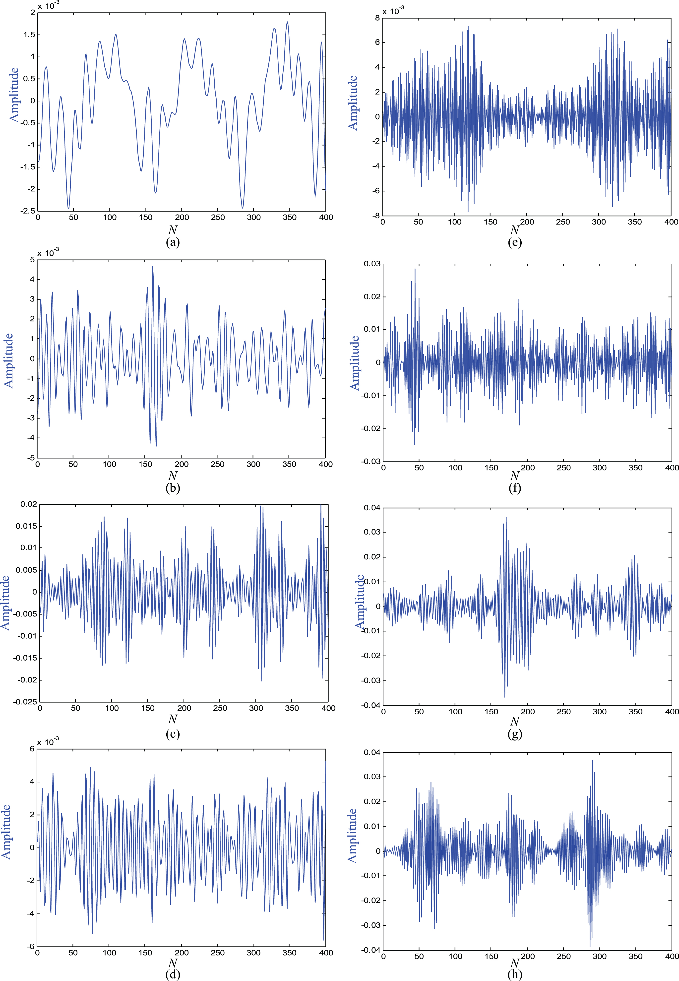
Frequency bands reconstructed by WPT of inner race fault.
In the present, only the decomposed signals of inner race fault are given, and the corresponding ten time-domain feature parameters are calculated using the equations listed in Table 1, the calculation results are recorded in Table 2.
The calculation results in each frequency band of each fault in simulations
To verify the feasibility of the simulation model based fault diagnosis method, experimental investigations using the same bearings as used in FEM simulation, are applied in this section. The experimental setup is shown in Fig. 6. Four different faulty signals are collected including inner race faults, rolling body faults, outer race fault and the combination of rolling body and outer race faults, as shown in Fig. 7(a-d), respectively. In the experiments, the rotation speed is kept constant at 1500 rpm, as well as in simulation. An accelerometer mounted at the top of bearing housing. The sampling frequency fs = 6000 Hz, and the signal length is N = 8000 points. Signals are acquisited by the accelerometer and sent to a computer through a signal conditioner (AVANT MI-7016). The measured vibration signals of four kinds of faults in bearings are shown in Fig. 8(a-d), respectively.

The experimental setup.
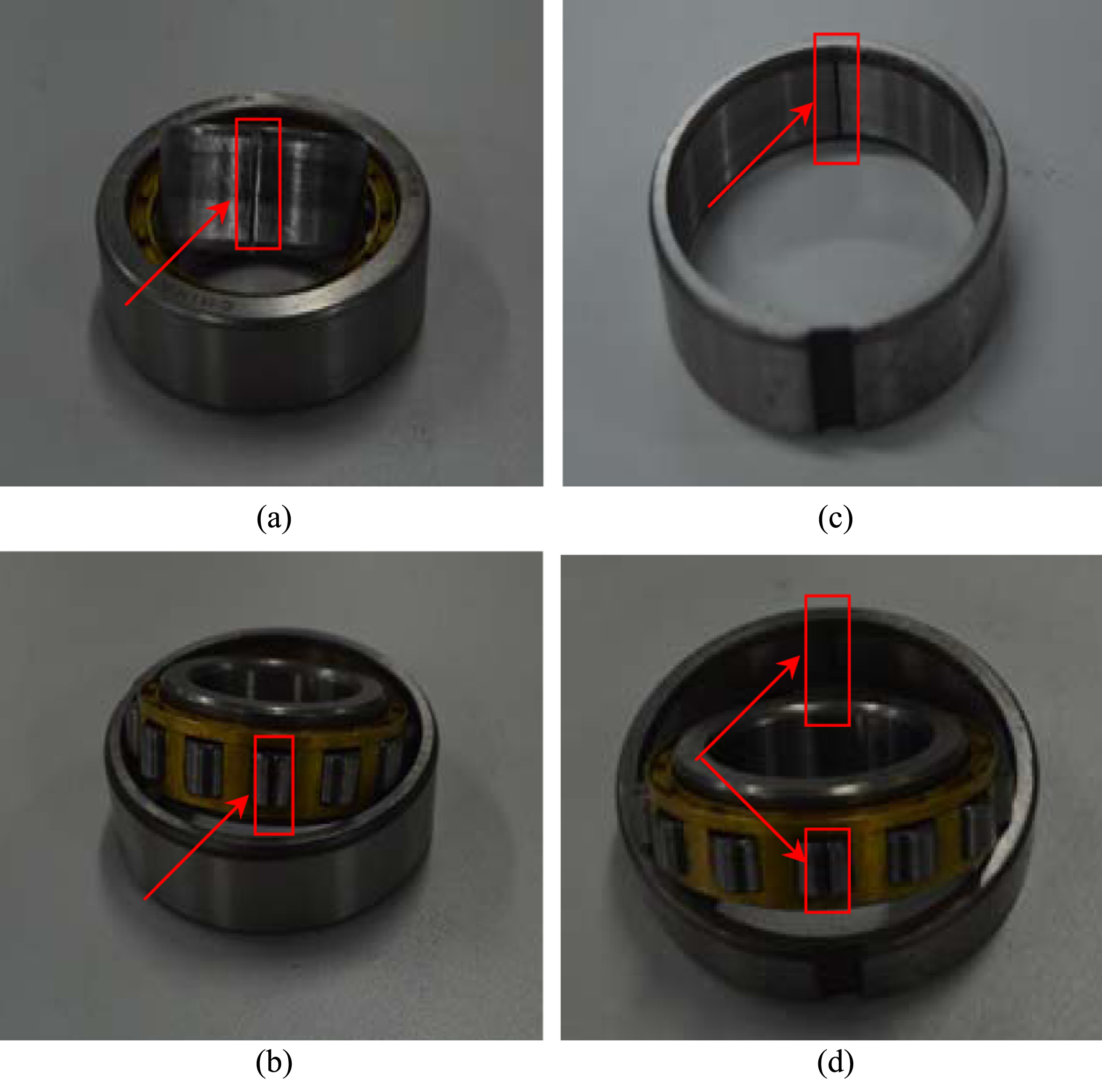
The faults in bearings. (a) the fault in inner race (b) the rolling body fault, (c) the outer race fault, (d) the combination of rolling body and outer race faults.
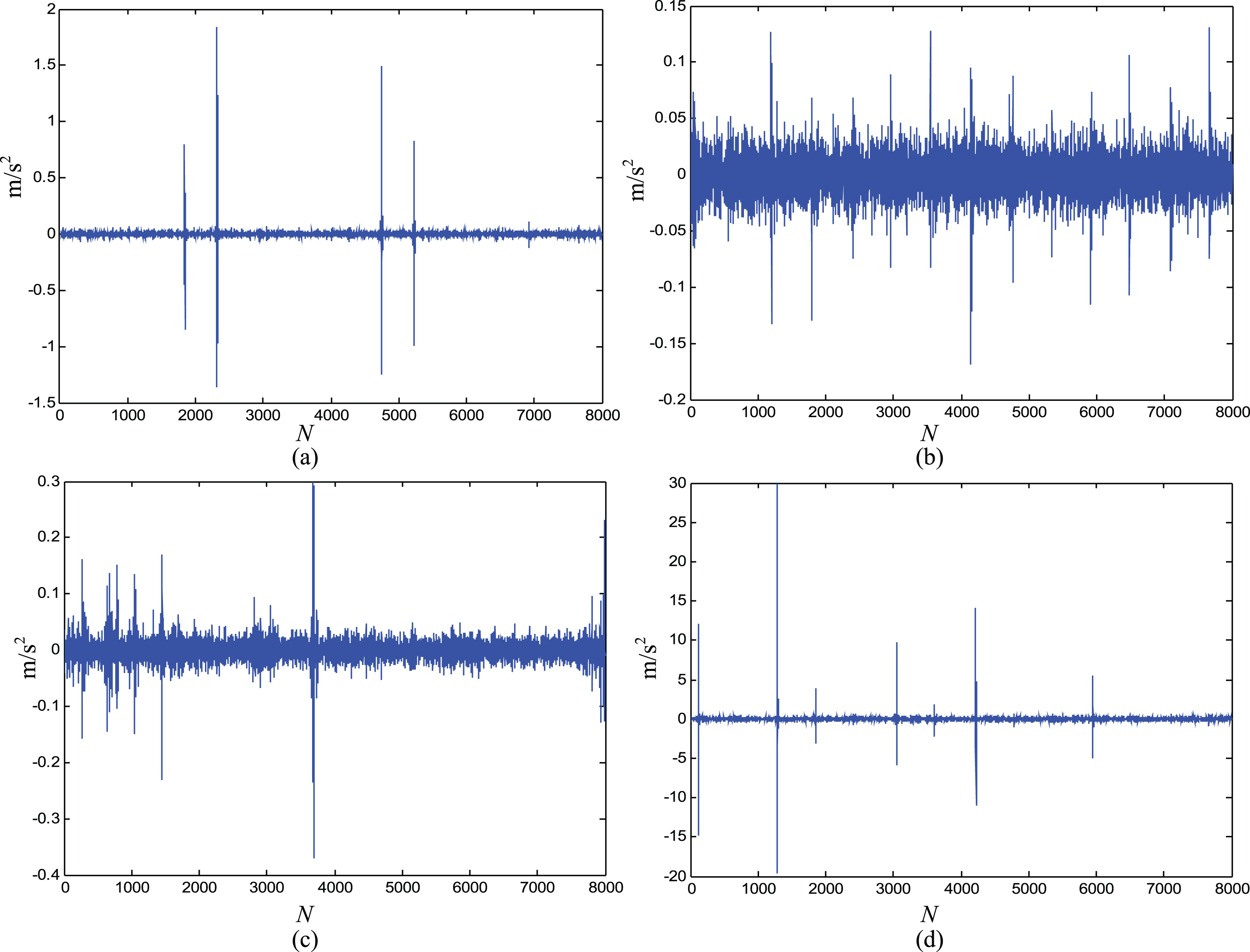
The measured signal with four kinds of faults. (a) the measured signal with inner race faults. (b) the measured signal with rolling body faults, (c) the outer race fault, (d) the combination of rolling body and outer race faults.
Then, using the procedures mentioned Section 2, eight frequency bands of measured vibration signals are obtained. Figure 9 shows the eight frequency bands (signal components) decomposed by WPT for the inner race fault. The calculation results of corresponding ten time-domain feature parameters are also listed in Table 3.

Eight frequency bands (signal components) decomposed by WPT for the inner race fault.
The calculation results in each frequency band for the four types of faults in the experimental setup
The method of SVM is applied to classify the fault type of the bearing. Table 4 presented the final classification results. The classification accuracy ratios for the inner race fault, rolling body fault, outer race fault, and the combination of rolling body and outer race faults are 79%, 81%, 71% and 76%, respectively.
The recognition results for the four types of faults
This paper suggests a faults detection method for bearing based on numerical simulation and support vector machine. The results show that the classification accuracy rates of inner race fault, rolling body fault, outer race fault and combination of rolling body and outer race fault are 79%, 81%, 71% and 76%, respectively. The results verified that the proposed method has the ability to detect the fault types of bearing. This method is possible to be extended to detect faults in more complex mechanical systems.
Footnotes
Acknowledgments
The authors are grateful to the support from the National Science Foundation of China (Nos. 51575400, 51505339, 51405346), the Zhejiang Provincial Natural Science Foundation of China (LQ16E050005).