
Abstract
This study focused on the high-precision and efficient steering control of a flexible chassis with a fuzzy-PI composite technique. The flexible chassis is a four-wheel independent steering and four-wheel independent drive electric chassis based on an off-centered steering axis module. The off-centered steering axis module is steered by jointly controlling the speed of the wheel and the locking torque of the electromagnetic steering lock. The fuzzy controller is applied to control the electromagnetic steering lock to reduce steering resistance and accelerate the steering process when the steering angle error is big, and the PI controller is designed to stabilize the steering process and to ensure the accuracy when the steering angle error is small. Simulation results showed that the proposed composite control system is very robust to steering angle without sacrificing high precision and efficiency.
Introduction
Electric vehicles (EV) yield superior fuel economy, lower emissions, and enhanced energy security compared to conventional internal combustion engine vehicles [1]. As opposed to the integrated driving system and steering mechanism in the traditional chassis, EVs with a four-wheel independent steering and four-wheel independent drive (4WIS/4WID) offer better driving efficiency, control flexibility, and maneuverability. The flexible chassis (FC) is a 4WID/4WIS EV with four off-centered steering (OCS) modules [3, 21]. Due to its omni-directional running, its main function is to control the vehicle on narrow roads in semi-closed or closed environments at low speed [22]. The OCS module is steered by jointly controlling the speed of the in-wheel motor (IWM) and the locking torque of the electromagnetic steering lock (ESL). The linear ESL control method renders steering angle accuracy and steering efficiency rather low.
This paper proposes a fuzzy-PI composite control method for the OCS system that can be applied to lock the ESL at appropriate value to ensure a “right and tight” steering process. The fuzzy controller is applied to control the EL to reduce steering resistance and accelerate the steering process when the steering angle error is big; and the PI controller is designed to stabilize steering and improve accuracy when the steering angle error is small.
Steering control has proven a challenging endeavor in terms of the 4WID/4WIS electric chassis. Existing single-wheel steering modes are based mainly on motor-assisting, which involves either direct-steering by the motor and gear unit or by other devices connected to the steering motor.
Several studies aiming at improving such a system have been developed by researchers from distinct institutions, such as, the Kanazawa Institute of Technology [20], Yokohama National University [19], Tokyo University in Japan [31]; and Pusan National University in Korea [18]. There are important research institutions currently focusing on this method in China, as well, including Nanjing University of Aeronautics and Astronautics [15], the Advanced Robotics Laboratory at Chinese University of Hong Kong [25–27], Shenzhen Automobile and Transportation Engineering Vocational and Technical College [23, 33], Jilin University [2, 9, 14], School of Control Science and Engineering College [5, 13], Changsha University of Science and Technology [10, 11], and Southwest Jiao Tong University [28]. Any existing steering control method for 4WIS/4WID EVs requires the use of a steering motor. So far, we have not found any study proposing an OCS system without a steering motor.
Fuzzy-PI theory has been explored from a wide variety of perspectives and has been applied successfully within many distinct research areas. A control algorithm based on adaptive equivalent consumption minimization strategy with fuzzy PI for hybrid EVs was introduced in a previous study [8]. Other researchers have demonstrated a fuzzy-PI controller for omnidirectional robot systems [17] and a longitudinal predictive re-entry guidance algorithm based on variable universe fuzzy-PI composite control [30]. An adaptive fuzzy-PI controller with shifted control singletons was developed in Nanjing University of Aeronautics and Astronautics [7]. A self-tuning fuzzy PI-based controller for DFIG wind turbine for transient conditions enhancement was presented by M Jazaeri [16]. And among the most fuzzy-PI controllers, fuzzy controller is used to accelerate the process when the angle error is big, and the PI controller is applied to stabilize the process and to ensure the accuracy when the steering angle error is small.
The rest of this paper is organized as follows. A theoretical review, including an introduction to the FC and its OCS system, is presented in Section 2. The OCS system steering model is presented in Section 3; and the fuzzy control and PI control algorithm are presented in Section 4. Section 5 details the simulations we ran to evaluate the proposed control technique, and it is followed by a concluding remarks section.
FC and OCS module: A Theoretical review
The FC is composed of four independent and symmetrically positioned articulations as depicted in Fig. 1 [3, 22]. Each articulation component combines an OCS axis, a leg, an ESL (FBD-050 from Taiwan KAIDE), and a DC brushless motor wheel (in-wheel motor from BATTLE). The OCS ensures that the IWM’s plane is parallel to the steering axis, but does not contain it, and that the steering axis and the IWM’s axis intersect at only one point. Once an articulation is placed at the right position, the system is designed to keep it in position by locking the ESL. A passive vertical suspension composed of springs connects the steerable wheels to the chassis, allowing the wheels to keep contact with the ground on uneven surfaces. The FC can change its direction by changing the direction of its four articulations, making the chassis omni-directional and allowing it to move within tight-space fields.
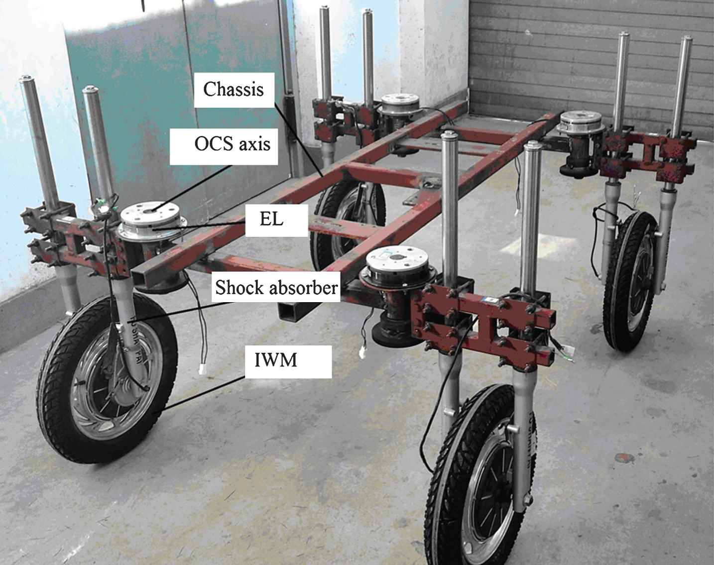
First sample FC vehicle.
To minimize the resistance in the steering structure, the conventional steering shaft is generally placed coplanar to the wheel rotation plane [5–28]; conversely, an off-centered bias, leaves a certain distance d from the wheel motion plane in the absence of a steering motor (Fig. 2).
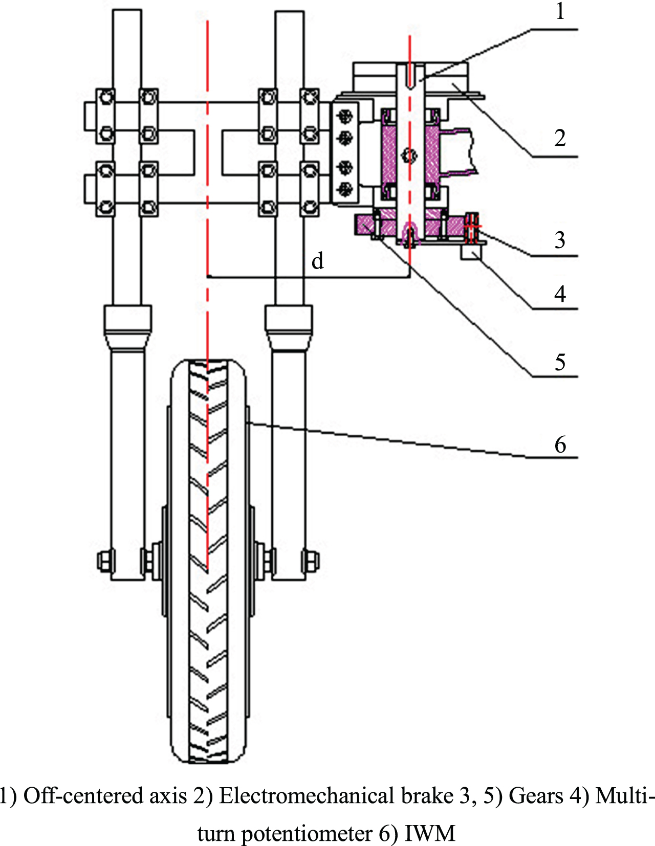
Location tracking structure on off-centered wheel (front view).
An off-centered automatic tracking bias device consists of an IWM, an OCS axis, a wheel supporting mechanism, a pair of gears, an ESL, and an angle detector resistor. When the IWM rotates around the OCS axis, the gears rotate following the axis, driving the detection resistor R1. The principle is that changes in resistance R1 track the steering position of the IWM; a precision multi-turn potentiometer is able to detect the rotation angle resistance.
A schematic illustration of an automatic tracking steering system based on a bridge circuit is demonstrated in Fig. 3.

Automatic tracking steering schematics based on Wheatstone bridge. Note: R i is bridge resistance and i = 1, 2, 3, 4; R0 is the zero-compensation resistor.
It mainly consists of a micro control unit (MCU), a step motor, a bridge circuit, an IWM, and a motor drive controller. When the FC wheels turn, the MCU controls the step motor to achieve to the desired angle, then the bridge arm resistance R2 is changed by the step motor causing dynamic imbalance in the bridge; the output of the bridge voltage and the signal controlled by the MCU are superimposed to force the IWM to accelerate or to decelerate. The electromagnetic lock is released so that the off-centered steering axis rotates around the frame structure, then the other arm bridge resistance R1 changes with the rotation and the bridge is restored to balance. The output voltage of the steering bridge reflects the difference between the steering axis and the target position, which is constantly fed back to the drive controller. The controller continuously adjusts the speed of the wheel to automatically follow the real-time balance position signal. When the target angle is reached, the electromagnetic lock switches back on again.
According to the literature [22], the target steering angle range of – 90° to 90° is recommended to allow the FC properly move to adapt itself to any required positioning The target angle is θ. Change in relative resistance at the potentiometer is calculated as follows:
Because the four OCS systems of the FC are independent of and similar to each other, only one OCS module was analyzed. Figure 4 shows a sketch of the OCS system structure.

Sketch of OCS system.
The steering in the OCS system is conducted by the speed difference between the chassis and IWM. The EL controls the entire steering process from start to finish. Based on the FC steering principle as expressed in Equation (2):
When the steering process is complete or when there is no steering or speed difference between the chassis and the IWM, the FC’s speed is expressed in Equation (3):
Based on the relationship between the IWM rotation speed and the control voltage, the angular velocity is expressed in Equation (4), as follows:
Combining Equations (1– 4) for the relationship between the steering angle and the steering angle, described in Equation (5), as follows:
The ESL controls the operation and end of the steering process, and based on the IWM movement characteristics, the IWM’s torque is expressed in Equation (6):
According to the relationship between the IWM torque and its drive current, the IWM’s torque can also be expressed in Equation (7):
And steering dynamic equation of the steering system is expressed in Equation (8):
And resistance torque of the steering system T
si
is expressed in Equation (9):
The accuracy and effectiveness of the system are significantly affected by the locking of the ESL, which prevents the traditional PI controller from achieving good performance. In this paper, a steering control system based on fuzzy-PI composite control is proposed. A diagram of control system structure is shown in Fig. 5. The fuzzy controller is applied to control the electromagnetic lock to reduce steering resistance and accelerate the steering process when the steering angle error is big, and the PI controller is applied to stabilize steering and to improve accuracy when the steering angle error is small.
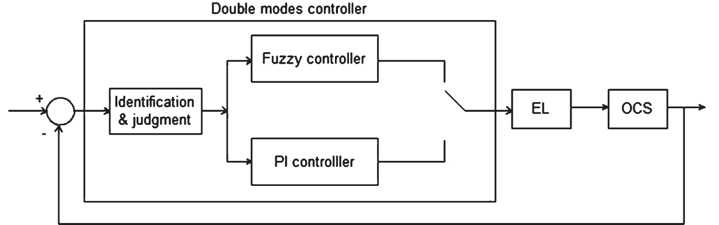
Fuzzy-PI control system structure.
Fuzzy control theory has been effectively applied in many fields and it has garnered a great deal of research interest. Designing a fuzzy controller is a complex and challenging task, especially in choosing the appropriate range of the universe and the form of membership functions.
The fuzzy domain of steering angle error E is [– 90, 90]; the fuzzy domain of derivative error for sideslip angle error Ec is [– 10, 10] and the fuzzy domain for output of fuzzy controller U, which is the voltage ratio of one control element calculated by Equation (8), is [0, 1]. According to practical experience with the OCS system, the basic fuzzy domain of sideslip angle error E and error derivative Ec are [– 0.1, 0.1] and [– 0.1, 0.1], respectively. The basic fuzzy domain of the angle ratio of left front wheel and the left rear wheel is [0, 1].
Then quantization factor and scaling factor were arbitrarily determined as follows.
Quantization factor of sideslip angle error: ke = 90/0.1
Quantization factor of derivative error for sideslip angle error: kec = 10/0.1
Scaling factor of control variable’s output: ku = 1/1 and the fuzzy subset of E, Ec, and U is [NB, NM, NS, ZO, PS, PM, PB}, in which the NB, NM, NS, ZO, PS, PM, and PB indicate negative large, negative medium, negative small, zero, positive small, positive medium, and positive large values, respectively. E and Ec are the error and error rate, respectively. Figures 6–8 show the membership function curves of E, Ec, and U, for which the triangle-type membership function is adopted.
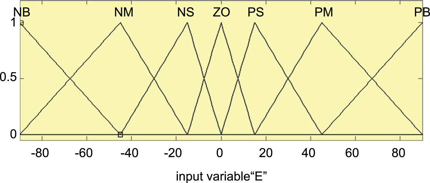
Membership function curves of E.
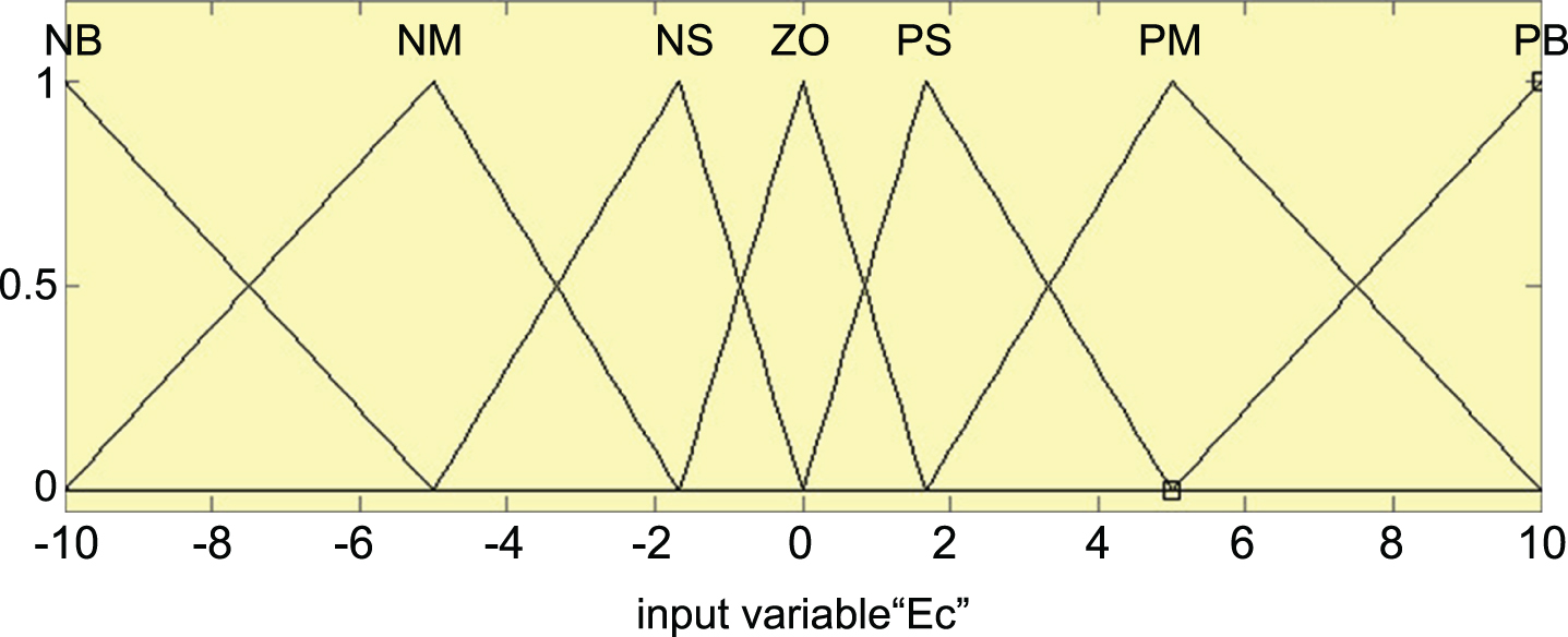
Membership function curves of Ec.

Membership function curves of U.
According to the actual situation, the fuzzy system makes a fuzzy judgment using a simple average method, then undergoes an anti-blur process in which the outputs of fuzzy sets are transformed into precise, optimized control variables. The rules of the fuzzy controller are as follows.
If E is PB and Ec is PB, then U is NB
If E is PB and Ec is PM, then U is NB
If E is PB and Ec is PS, then U is NB
If E is PB and Ec is ZO, then U is NB
. . .
As shown in Table 1, there are a total of 49 rules in the fuzzy logical controller.
Fuzzy rule table
As explained above, when the steering angle error falls within a designed small range, the fuzzy-PI controller switches to the PI control model. The PI controller, per common PI control protocol, mainly advances to stable state capability by integral learning.
The PI arithmetic can be described in increment form as follows:
The next problem to be solved is to confirm k
p
and k
i
. First, we set an initial value approximating a priori knowledge and experience for the system, and then adjusted it through experiment until an ideal control result was achieved. The final control was obtained as follows:
Figure 9 shows a flow chart of the control system structure. In Fig. 9, “es” marks the allowable error of the theoretical downrange.

System structure flow chart.
Simulations
The steering model of the OCS module was built in Matlab/Simulink. The simulation system was started making OCS axis automatically track the setting angle given by the user after 1.5 s of system operation time. To verify the correctness of the proposed steering control method based on Fuzzy-PI control strategy, we ran comparisons between the proposed Fuzzy-PI model, Fuzzy-only model, and PI-only model. The input situations included an OCS module setting angle from – 90° to +90° and the parameters of the OCS system and FC listed in Table 2.
OCS system and FC parameters for comparative simulations
OCS system and FC parameters for comparative simulations
Simulation results were expressed as means± standard deviations (SDs) over 5 replicates. All the statistical analyses were done using the statistical software SPSS 15.0 version (SPSS inc., Chicago, IL, USA).
After steering angle was set at – 90° and – 90°, one of the steering process of OCS system based on Fuzzy-PI, PI-only and Fuzzy-only simulated by the Matlab toolbox is shown in Fig. 10. And the response steering angle means that the final stable angle of OCS axis, and the response steering time means the time taken for OCS axis to rotate from the beginning of 0° to the final stable angle.
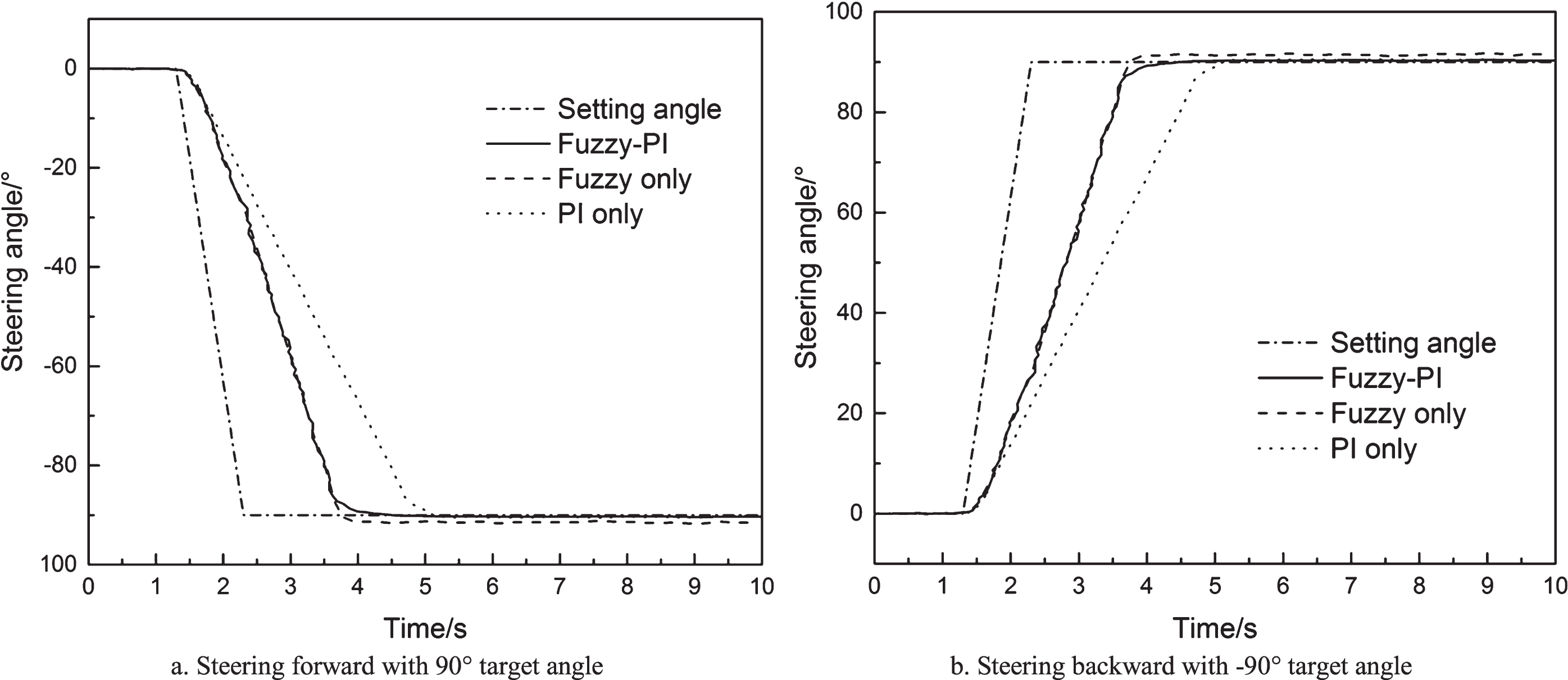
Simulation results.
As shown in Fig. 10, after the target steering angle was set, the response steering angle responded in one of three ways to control the ESL to achieve automatic tracking of the target steering angle. Figure 10(a) shows the response steering angle’s changing process as the OCS axis steers the system forwards. When the target steering angle was set to +90.00°, the response steering angle of Fuzzy-PI, PI-only, and Fuzzy only were 90.30°, 90.31°, and 91.02°, respectively; the response steering time of Fuzzy-PI, PI-only, and Fuzzy-only were about 3.160 s, 3.722 s, and 2.541 s, respectively. Clearly, the Fuzzy-PI controller and PI-only controller achieved better response steering angle accuracy than the Fuzzy-only controller. The proposed model took less time than the PI model, as well.
Similar results were obtained for the steering angle response as the system was steered backwards, as shown in Fig. 10(b). When the target steering angle was set at – 90.00°, the response steering angle of Fuzzy-PI, PI-only, and Fuzzy-only were – 90.30°, – 90.31°, and – 91.02°, respectively; the response steering time of Fuzzy-PI, PI-only, and Fuzzy-only were 3.160 s, 3.722 s, and 2.541 s, respectively.
To further enhance the accuracy and effectiveness of the Fuzzy-PI model, we ran additional simulations with different target steering angles and IWM rotation speed of 60 r·min–1. Tables 3 and 4 describes the simulation results per the response steering angle and response steering time for steering forward and backward, respectively.
Results of steering angle control test on OCS system for steering forward
*Mean values are not significantly different (P > 0.05) for the same capital letters within a row among the target steering angles, and for the same lower case letters within a column among the controllers.
Hypothesis test (t-test) was performed among the simulation results of Fuzzy-PI, PI-only, and Fuzzy-only. As shown in the Tables 3 and 4, the response steering angle can achieve automatic tracking target steering angle after the target steering angle was set regardless of how the ESL was controlled. The mean response steering angle and response time increased with the target steering angles. The response steering angle of 3 controllers showed that there were no significant differences (P > 0.05) between the Fuzzy-PI controller and the PI-only controller with different target steering angles, while significant differences (P > 0.05) were observed between the Fuzzy-PI controller and the Fuzzy-only controller, indicating that the Fuzzy-PI controller yield better steering angle accuracy than the Fuzzy-only controller. The response time of 3 controllers showed that there were significant differences (P > 0.05) between the Fuzzy-PI controller, the PI-only controller and the Fuzzy-only controller with different target steering angles, indicating that the Fuzzy-PI controller took less time than that of the PI-only controller and more time that of the Fuzzy-only controller. Considering both accuracy and efficiency of OCS system, the Fuzzy-PI controller, combined with the advantages of both the PI-only controller and the Fuzzy-only controller, is very robust to target steering angles without sacrificing very high accuracy and efficiency.
Results of steering angle control test on OCS system for steering backward
*Mean values are not significantly different (P > 0.05) for the same capital letters within a row among the target steering angles, and for the same lower case letters within a column among the controllers.
In this study, an OCS module was successfully steered by jointly controlling the rotation speed of the IWM and the locking torque of the ESL. This paper introduced a fuzzy-PI composite control method for setting the proper ESL locking torque for a “right and tight” steering process. The fuzzy controller is applied to control the ESL to reduce steering resistance and accelerate the steering process when the steering angle error is big; the PI controller is utilized to stabilize steering and improve accuracy when the steering angle error is small.
An OCS module steering model was established in Matlab/Simulink for comparative simulations on response steering angle and steering time between Fuzzy-PI, Fuzzy-only, and PI-only at IWM of 60 r·min-1. The results indicate that the Fuzzy-PI controller is very robust to steering angle and can achieve better accuracy than Fuzzy-only controller and higher effectiveness than PI-only controller. We hope that the results presented here provide a useful reference for advanced steering systems of 4WID/4WIS EVs.
Footnotes
Acknowledgments
This research was supported by research grants from General Program of National Natural Science Foundation of China (51375401).