
Abstract
There are two kinds of electronic components—passive and active. One of the most used electrical components is diode, because of its ability to convert AC (alternate current) power supply into DC (direct current) for use in the daily life. A diode can be used as both full-wave and half-wave rectifier. Bridge circuit theory is commonly applied to full-wave rectifiers in soft computing engineering. This feasibility based on circuit simulation study aptly uses bridge circuit theory in a half-wave rectifier by replacing two diodes from a block with two resistors and providing only one positive input. The experimental results verify that the bridge circuit theory works fairly well with half-wave rectifier, and the output is the same as that of a simple half-wave rectifier circuit.
Introduction
Electronic devices are popular in our society since the beginning of 20th century. TV, mobile phone, game console, etc. are widely used to fulfill daily needs of humans. These devices can perform well because of their internal components. There are two kinds of components—passive and active. A component that cannot generate its own electrical energy but derives it from another source (voltage or current source) and converts it into power dissipation or magnetic or even electrical field energy is called a passive component. The other kind is the active component that can generate its own electrical energy and provide energy to the circuit or even to another passive component [1–6].
In this paper, one of the very common active components called diode is discussed. Diode is a combination of two words that represent its structure, “di” means two and “ode” implies electrode. Therefore, diode is a combination of two electrodes made of a combination of semiconductor materials of type-n and type-p, which is known as a pn junction [10–13]. It uses a crystalline piece of semiconductor material—the commonly used material is silicon but often Germanium and Selenium are used as well. Diodes can operate by establishing one-way flow of current and inhibits the reverse direction—acting as signal rectifier and alternating current (AC)-to-direct current (DC) converter [2–4].
The most common use of diode in our daily life is that as a rectifier. Many electronic devices use diode because of its AC to DC converter ability. The power source at our home is an AC supply of ∼220 V. Therefore, in order to use devices such as TV, radio, phone charger, etc., the AC power supply should be rectified first. This is where diodes become important [5–9].
This paper is structured as follows: Section 2 presents the basing in diode and methods deployed. Section 3 explains the characteristic curve for the proposed diode as rectifier. Section 4 describes the diode as rectifier. Section 5 discusses the bridge circuit obtained and Section 6 concludes this paper.
Biasing in diode
The majority carriers of the P side or the Anode are holes (+) and that of the N side or cathode are electrons (–). Between both of them, there is a region called depletion region where there are no charge carriers (neither electrons nor holes). However, there is an equivalent voltage in this region called the barrier voltage and the value depends on the semiconductor material—0.6 for Silicon and 0.2 for Germanium. The movement of charge carriers caused by diffusion current and drift current occurs in this region. Diffusion current is generated when there is a movement of charge carriers (holes/electrons) from a region of high to low concentration. On the other hand, drift current is generated when there is an electric field that makes the charge carriers move. A stable situation is obtained when both the currents are in the same direction. It affects the occurrence of forward bias and reverse bias [10–13].
Forward bias
Figure 1 shows that forward bias occurs when the positive and negative pole of the battery are connected to the anode and cathode respectively. Since there is an excess of electrons on the N side (because of its majority charge carrier), they will be repulsed by the negative pole of the battery. If the electrical energy of the battery is higher than the barrier voltage of the diode, the repulsed electrons will pass through the depletion region and will combine with holes on the P side, and thereby reducing the depletion region. This will continue to go on as long as the loop is closed. The condition that causes drain of electrical current in the circuit is given by the expression below [8–11].
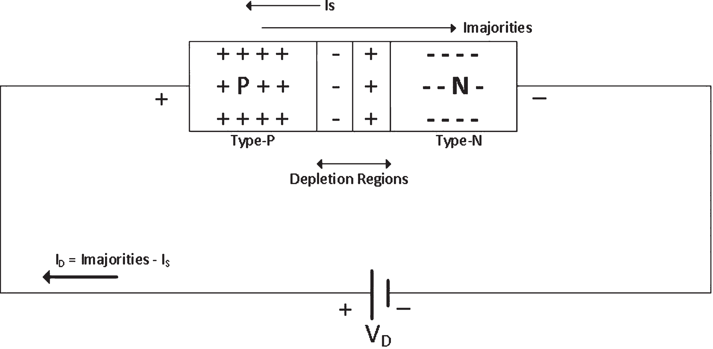
Forward bias.
Figure 2 shows the opposite situation of forward bias, i.e., reverse bias, when the negative and positive poles are connected to anode and cathode respectively. In this situation, there will be no drain current because electrons on the N side are attracted by the positive pole of the battery and the holes on the P side are attracted towards the negative pole—making the depletion region increase. If the reverse bias voltage is increased, there will be a certain point when the diode will be broken—that point is called the breakdown voltage. Reverse bias is shown by the following equation.

Reverse bias.
Figure 3 shows the diode characteristic curves. We know that diode can only drain one way current flow, which happens in forward bias condition. The right side of Fig. 3 shows the Forward bias curves, where 0.2 V represents the barrier voltage of Germanium diode and 0.6 V represents that of Silicon diode. Therefore, the barrier voltage is the minimum voltage that can make the diode work by draining one way current flow [10–13]. For an ideal diode, the minimum voltage required for drain current is zero. The left side of the curve shows the reverse bias condition. When the voltage is already below 0 V, there is no current in the diode. The breakdown voltage is represented by the point where the curves suddenly start moving downward, and the value depends on the type of diode [5–9].

Diode characteristic curve.
A diode has many applications such as in Clipper circuit, Clamper circuit and Rectifier circuit. The most used application in real life is the rectifier circuit to rectify signal from AC to DC [5–10]. There are two types of rectifier diodes, half-wave and full wave rectifier with simple circuit that consists only diode and resistors as explained below.
Half-wave rectifier
As the name implies, a half-wave rectifier passes just one half of each complete signal wave of the AC power supply in order to convert it into a DC supply.
In Fig. 4, during a half cycle of positive AC wave, the diode is forward biased as the positive pole of the battery is connected to anode or we can use Equation (1) to make sure that the diode is forward biased. It means that the diode becomes a short circuit (ideal condition).
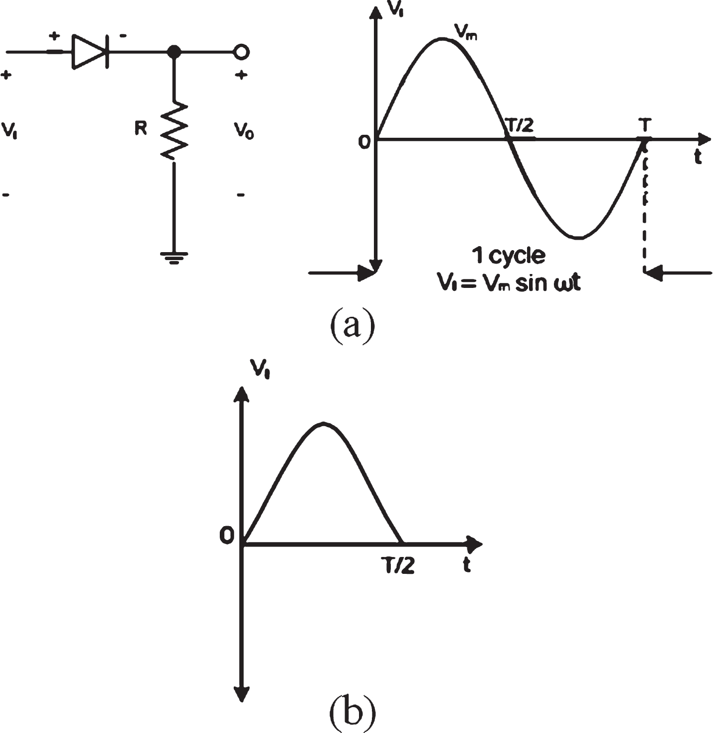
Half-wave rectifier: (a) circuit and input, (b) the output.
During a negative half cycle of AC wave, the diode is reverse biased as the anode is now connected to negative pole of the battery or we can use Equation (2) to make sure that the diode is reverse biased. In this situation, the diode becomes an open circuit, i.e., there is no current flowing in the circuit (I = 0), and hence there is no output voltage.
Therefore, there will be an output for a half-wave rectifier only when a half cycle of positive AC wave is fed into it.
Different from the half-wave rectifier, a full-wave rectifier will rectify a full signal of AC wave using two diodes that can work in both cycles.
In Fig. 5, during a positive half cycle of AC wave, the first diode is forward biased as the positive pole of the battery is connected to anode or we can use Equation (1) to make sure that the diode is forward biased. Therefore, the first diode becomes a short circuit (ideal condition). However, the second diode will become an open circuit because it is reverse biased. Therefore, for the first half cycle, the current flows through the first diode to the load. Based on the Ohm’s law, the output of the first wave through first diode is:
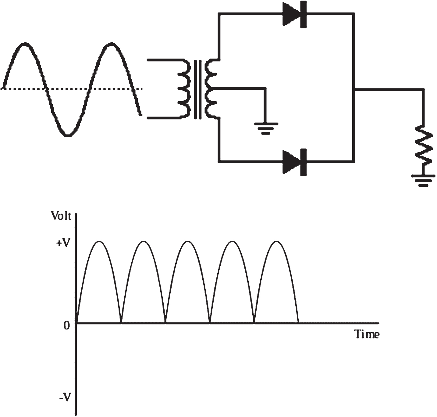
Circuit and output for full-wave rectifier.
During the negative half cycle, the second diode is forward biased. Therefore, for the second cycle, the first diode acts as an open circuit and the second diode acts as a short circuit. The current flows through the second diode. The output of this cycle is the same as that of the first cycle, i.e., it follows Equation (6). As a result, the system has fully rectified all cycles into one phase.
LTSpice, a SPICE(Simulation Program with Integrated Circuit Emphasis)) simulator of electronic circuits, produced by semiconductor manufacturer LTC(Linear Technology), is used in this study for implementing rectifier diode based on bridge circuit. Bridge circuit is an electrical circuit topology where two circuit branches are “bridged” by a third branch connected between the first two branches at some intermediate point.
Full-wave rectifier
Bridge circuit in full-wave rectifier is a common application. It consists of four diodes “bridged” with one another making two blocks.
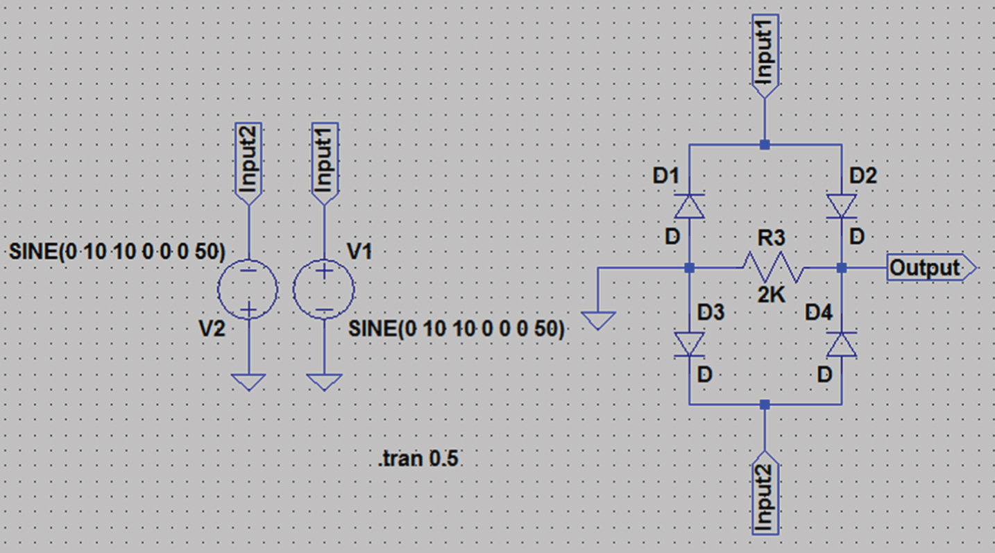
Using LTSpice, the two blocks of Fig. 6 are made up with D1, D2 and D3, D4 respectively. Full-wave rectifier requires two different input signals for two blocks.
Full-wave rectifier Output.

Full-wave rectifier LTSpice schematic.
For the first cycle, i.e., the positive half cycle, the first and second block get a positive and a negative AC wave respectively. The first block is forward biased—D1 and D2 are short circuit, and the second block is reverse biased—D3 and D4 are open circuit. Therefore, the current flows through the first block and the output of the first wave is given by
For the second cycle, the reverse situation occurs. Under this condition, the first block is reverse biased and open circuit, and the second block is forward biased and close circuit. The output is the same as that of the first cycle.
Therefore, the output of full-wave rectifier while using a bridge circuit is the same as that of using a simple circuit consisting of two diodes. Figure 8 shows the output signal. The color blue and green denote the input and output signal respectively.
Half-wave rectifier LTSpice schematic.
The second step is to use a bridge circuit in half-wave rectifier. There are several differences in the circuit as compared to the full-wave one. First of all, we just need one block of diode. However, since it is a bridge circuit, the second block is not fully removed; the two diodes of the second block are replaced by resistors. Consequently, we just need one input for the first block. Therefore, the input of the second block is grounded.
For the positive half cycle, the two diodes are forward biased and become a close circuit. The current flows and the output signal is:
However, for the negative half cycle, the two diodes are reverse biased and become an open circuit. Therefore, there will be no current in the circuit (I = 0) and the output will vanish as suggested.
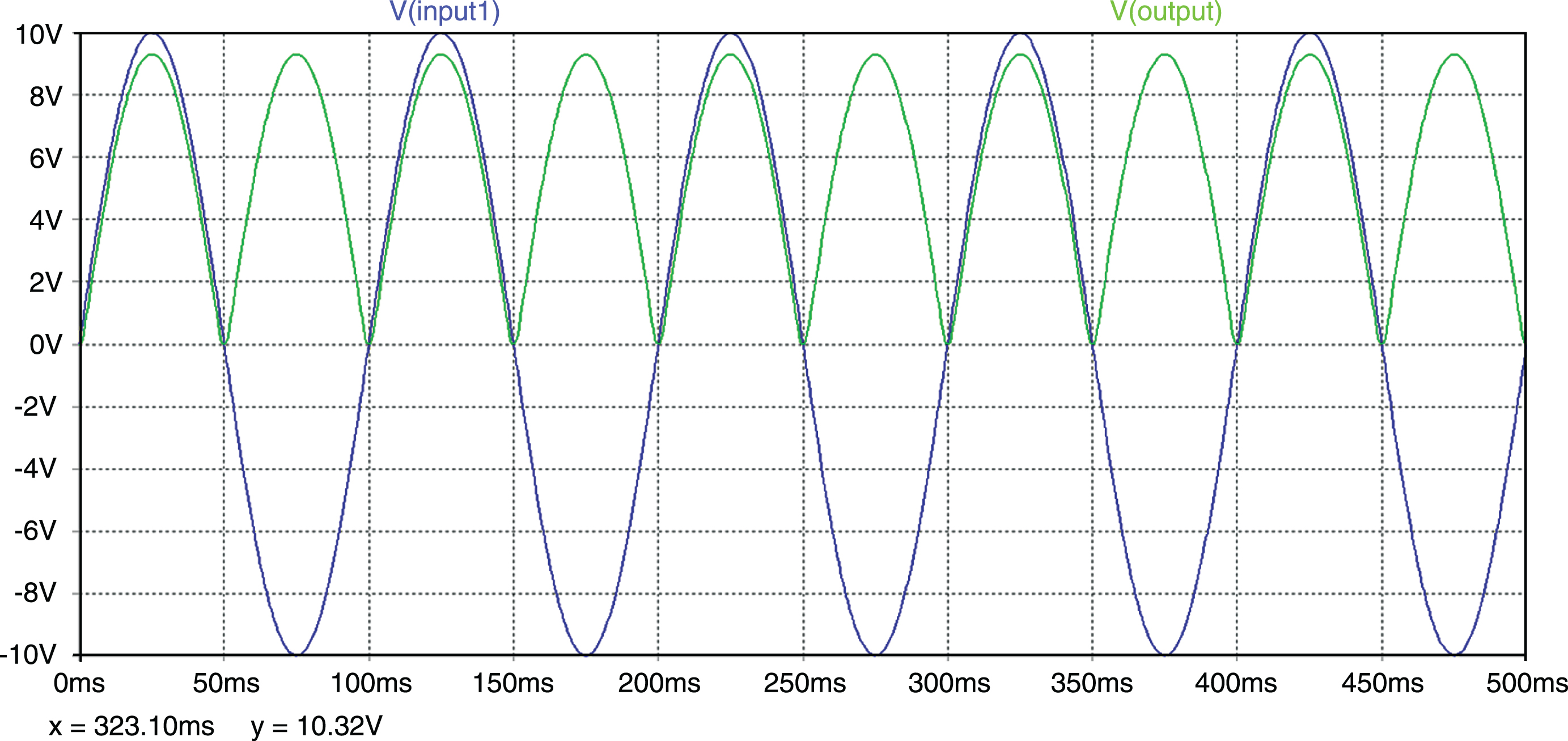
Therefore, the output of half-wave rectifier while using a bridge circuit is the same as that of using a simple circuit consisting of only one diode. The output signal is shown in Fig. 9, where the color green and blue denote the input and output signal respectively.

Half-wave rectifier Output.
The result confirms that the bridge circuit theory works well with half-wave rectifier, and the output is the same as that of a simple half-wave rectifier circuit. For future work, a high-frequency rectifier diode can be implemented. At present, rectifier diode can only rectify low-frequency signal, because every diode needs a period of time to recover its reverse resistance after voltage polarity changes. This reverse current makes the diode generate some heat. The higher the frequency is, the more time is spent in the recovery state and more heat is produced by the reverse-recovery process. Therefore, a rectifier is needed for higher frequency, because it can be implemented in optical heterodyne detection such as in optical fiber communication.
Footnotes
Acknowledgments
This research was supported by Kumoh National Institute of Technology (2018-104-113).