
Abstract
Contrasted with common obstacle avoidance mode based on single sensor or solo algorithm, this article put forward an intelligent pattern based on Combination from CNN-based Deep Learning Method and liDAR-based Image Processing approach. As for Deep Learning method, a 10-layer Convolutional Neural Network (CNN) is designed which comes to a high recognition accuracy of 97 percent in Tensorflow and success rate of obstacle avoidance is over 90 percent. With regard to liDAR-based Image Processing approach, decision is made by a special method of counting the number of Point Cloud Data (PCD) which is generated by 2D liDAR and a success rate over 90 percent is achieved as well. When two kinds of methods work together, a robust success rate of 100 percent is realized. Meanwhile, Inertial Measurement Unit (IMU) and Xbox360 are taken into consideration for Pose Estimation and Data Collection. Finally, all functions are integrated in Robot Operation System (ROS) on platform of nVidia Jetson TX1.
Introduction
Background and related research
The traffic accidents occur frequently all over the world. One of the crucial reasons is the human mistake. for instance, drunk driving, fatigue driving, drag racing, etc. Autonomous driving technology, especially the obstacle avoidance technique, is helpful for eliminating the threat of human operation error and realizing the aim of safety driving. What’s more, autonomous obstacle avoidance technique also has great social significance in assisting the handicapped to get around. Developed countries such as Germany and the US have been involved in the research of autonomous vehicles since the 1950s and great progress has been made in some universities and corporations just like MIT, Google, Tesla, Benz, BMW and so on. In China, the institution of National University of Defense Technology (NUDT) and TongJi University (TJU) are outstanding in the field of autonomous vehicle. As for corporation, BaiDu corporation works as one of the leaders not only in China but also in the world. Automatic obstacle avoidance technique is one of the essential technologies in autonomous driving and the method from different research institutes and individuals varies for the purpose of high and stable success rate of obstacle avoidance.
On one hand, the majority of researchers realize the function of obstacle avoidance by using single sensor, solo algorithm, and its optimization. As to the method based on single sensor, the aim of obstacle avoidance can be reached by using ultrasonic sensor within a fuzzy environment [1], processing optical flow in monocular camera stream [2], designing novel image processing procedure based-on Inverse Perspective Transformation (IPT) using a monocular camera [3], taking Fuzzy Ant Colony Optimization (FACO) method using ultrasonic transducers [4] as well as the vision-based method with fuzzy logic in webcam [5] and strategy based on the measured liDAR data on the self-developed Arduino based RC Car [6]. As for the method of solo algorithm or its optimization, for instance, model predictive control-based obstacle avoidance algorithm [7], receding horizon control algorithm by resorting to set-theoretic ideas and Sum Of Squares (SOS) decomposition techniques [8], supervisory control algorithm based on a barrier function method which works in a plug-and-play fashion [9] and automatic worst-case search algorithms based on using potential field method [10] are the typical implementations. In addition, some researchers take more intelligent way based on Machine Learning to design the obstacle avoidance system like the Interval Type-2 Fuzzy Neural Network (IT2FNN) [11], Spiking Neural Networks (SNN) [12], Q-learning and a neural network planner [13]. Apart from the method mentioned above, there exist various of novel strategies in designing the obstacle avoidance system, for instance, the Dynamic Window Approach (DWA) for obstacle avoidance [14], nonlinear model predictive control which generate the collision-free trajectory [15], Non-linear Model Predictive Control (NMPC) strategy for a kinematically redundant space robot to approach an un-cooperative target in complex space environment [16], technique for avoiding obstacles based on the behavioral structure [17], novel control scheme with nonholonomic constraint [18], method using nondifferentiable control Lyapunov function [19], and magnetic field-based obstacle detection and avoidance system [20].
On the other hand, a lot of researchers also search for the method of uniting different algorithms or sensors together to make the co-decision for obtaining a stable success rate. Such as a novel coordinated steering and braking control strategy based on the nonlinear backstepping control theory and the adaptive fuzzy sliding-mode control technique [21], method of combining the algorithm of reinforcement Q learning with the extreme machine learning algorithm optimized by particle swarm [22], method of uniting fuzzy control and neural network control together [23], collaborative way based on Acoustic Information and Optical Image [24], cooperative manoeuvring approach including both local and global obstacle avoidance [25] as well as intelligent robotic car which involves laser, camera, and velodyne [26] and shared control framework for obstacle avoidance and stability control using two safe driving envelopes [27].
Analysis of previous works and objective of this article
After summarizing the method of obstacle avoidance technique in recent years, conclusion is drawn that whether the obstacle avoidance way based on solo optimized algorithm or the way based on collaborative methods, both of them have obtained a decent performance. However, when encounter the extreme situation with various of interference factors, the method based on solo algorithm exposes its defect of lower robustness. In addition, although the optimization of solo algorithm can promote the robustness and efficiency to some extent, however, it also cost a lot of energy and time commonly and the efficiency is limited when compared with the collaborative method like multi-sensor fusion technique which is prevalent in recent years in the field autonomous vehicle. What’s more, collaborative technique has shorter R&D cycle and the performance and efficiency is more decent from the perspective of industry.
In term of collaborative method, what kinds of obstacle avoidance techniques should be adopted and how to combine them to work together varies from one to another among researchers and the final performance varies as well like [21–27]. From result of previous investigation, the traditional liDAR- -based obstacle avoidance technique is a mature scheme which is under commercial deployment for many years. With regard to Deep Learning approach, which is more intelligent and advance and has better performance and efficiency in special situation. So, how to fuse traditional and frontier techniques together to realize a better performance is one of the prevalent trends of future which must take into consideration from the perspective of industry deployment.
In view of this, this article is based on the idea of collaborative technique or multi-sensor fusion technique for its decent performance and shorter R&D cycle. A collaborative obstacle avoidance scheme in car with high efficiency and robustness is put forward which using traditional liDAR-based obstacle avoidance technique as well as the technique of CNN-based Deep Learning. What’s more, the car equipped with collaborative system owns transplantable capability which can easily be transplanted into various robotic car like electromobile (like (a) in Fig. 1) or Unmanned Aerial Vehicle (UAV) (like (b) in Fig. 1).
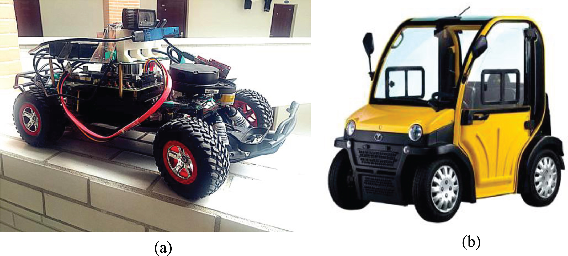
Obstacle avoidance car of our project (a) and commercial electromobile (b).
This article describes the software design, hardware design, experiments of obstacle avoidance car. It’s organized as follow:
Section 2 describes the design of obstacle avoidance algorithm and ROS node which involves the model design and visualization, Deep Learning method based on CNN, the design of liDAR evasion mode based on statistical method, the design of Xbox360 controller, the design of Command Processing Centre Node, and the design of Data Recorder. Section 3 describes the hardware design, experiments, and conclusion. Finally, the discussion as well as future works are demonstrated.
Model design and visualization
The language of XML is adopted in the process of of model design. Then, integrity of car model (Fig. 2) can be checked out by starting the function of RViz.
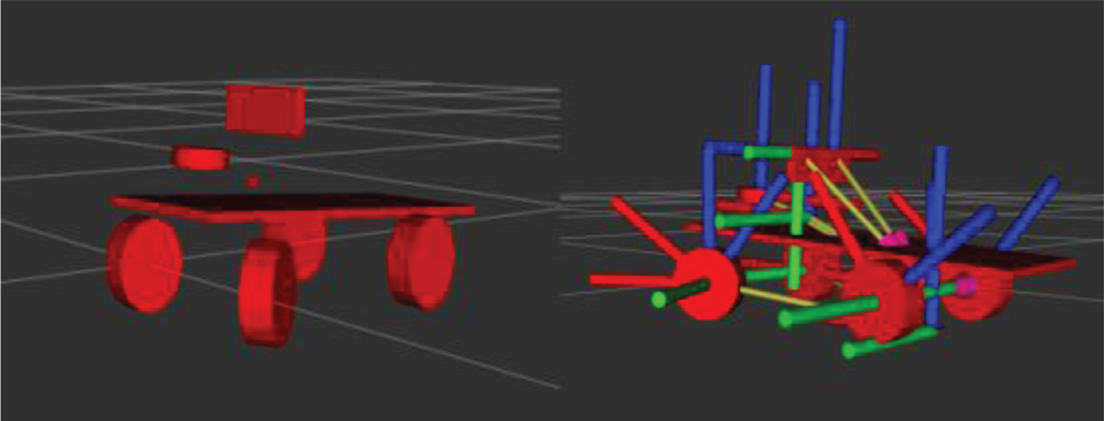
Car model in RViz.
The design of CNN framework
CNN works as a kind of feedforward neural network. Its artificial neurons can respond to a portion of the surrounding unit which leads to the high-performance in the field of matrix computation especially in image processing. The process of image recognition can be divided into several components in general, for instance, data acquisition, data preprocessing, training model design, test model design, model training and model test, etc.
As for data acquisition, the RealSense camera is the core sensor. There are two main destination for the image acquired. The first one is Data Recorder Node which will be detailed in
The raw image set we collected is not qualified for recognition model training or retraining and it must get through the preprocesssing phase which uses the library of openCV.
Firstly, cv2.imread() method is adopted to read the image set to procedure.
Secondly, the size of the image must be trimmed to 200×150 and the method of cv2.resize() can archive this goal.
Thirdly, grayscale threshold method is taken to process the image.
The fourth step is to process the label of image and extract the value of steering and throttle.
The last step is using the methods of y.append ((steering, throttle)) and x.append(img) for generating the label of training image and generating the image set of training. Meanwhile, 80 percent of the images are used for CNN model inputs and the rest of the images are taken to check the recognition rate of the model. Otherwise, each 100 images are encapsulated to a batch and send to model.
The framework of model for training is same as test model (Fig. 3). considering that the embedded system is not suitable for the large-scale CNN model. So, a 10-layer neural network framework is constructed in which 5 CNN layers are used for extracting the high-dimensional features, one flatten layer is used to flatten the outputs of the fifth CNN layer to acquire a simple vector output, and 4 full-connection (fc) layers work as classifier to classify the features extracted in CNN layer.
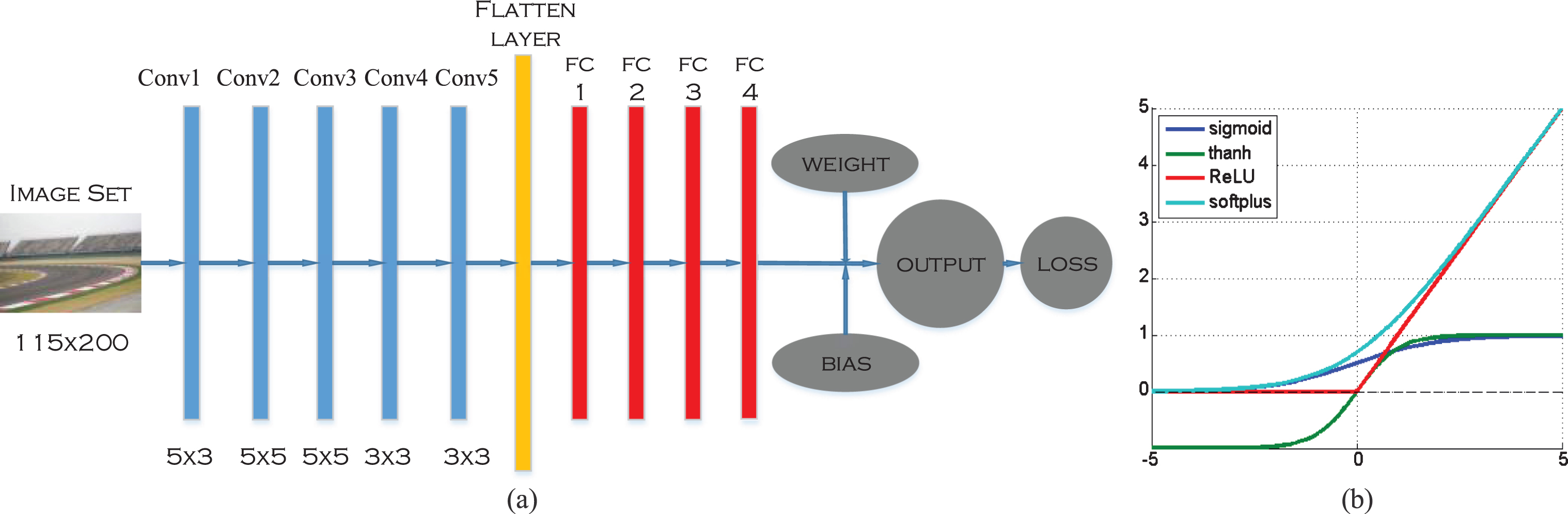
CNN model (a) and curve of ReLU compared with sigmoid, thanh, and softplus (b).
In CNN layers, the convolution kernel of first three layers is 5×5 and the rest two layer’s is 3×3. Getting through the processing of flatten layer, the output number is 512 and then they are sent to fc layer for classification. ReLU (Fig. 3) is chosen as activation function in fc layer for its higher performance in convergence, computing efficiency, overfitting avoidance better than tanh, softplus and sigmoid. The output class number of each fc layer are 512, 100, 50, and 10. Then, the method of tf.matmul() is taken to add the value of weight and bias to get final output and the method of tf.reduce_mean() is used for computing the value of loss. As for the optimizer, the Adaptive Moment estimation (AdaM) algorithm is taken into account for its high performance in tackling nonconvex optimization problems.
The following equations are the principle of the AdaM algorithm:
Firstly, set the value of learning rate (η), exponential rate of first moment estimates (μ), exponential rate of second moment estimates (υ) and constant for numerical stability (ɛ). and then, initialize first moment vector, second moment vector and timestep to zero which are presented in Equation (1).
Secondly, Equation (2) is adopted to compute the gradients (g
t
) at time t.
Thirdly, update the biased first moment estimate (m
t
) and second moment estimate (n
t
) using Equations (3) and (4).
Fourthly, compute biascorrected first moment estimate (
Fifthly, update the parameters (θ
t
) by Equation (7).
Finally, compute and print the value of recognition rate and loss. The test demonstrates that the recognition rate of CNN model is up to 97 percent after being trained with 10 thousands images.
The primary step in the design of ROS package is initializing CNN model and various of functions like CvBridge(), XBox360(), etc. Then, subscribe the image from RealSense camera and control message from Xbox360 with the method of rospy.Subscriber(). the following descriptions are how to deal with the images and control messages received:
As for image processing, the method bridge.imgmsg_to_cv2() is taken to transform the image which is the ROS format to the openCV format so as to be recognized by openCV. Then, trim the size of image using cv2.resize() to 200×115 and compute the steering angle with the method of model.y_out.eval(). Finally, transform the format of steering angle to the ROS format.
With regard to control message from Xbox360, button event messages are acquired using controller.buttonEvents() method to initialize the obstacle avoidance mode of CNN. In the end, rospy.Publisher() method is adopted to publish two kinds of messages in order to provide the input data for the Command Processing Centre Node. The Deep Learning mode in ROS is briefly demonstrated in Fig. 4.
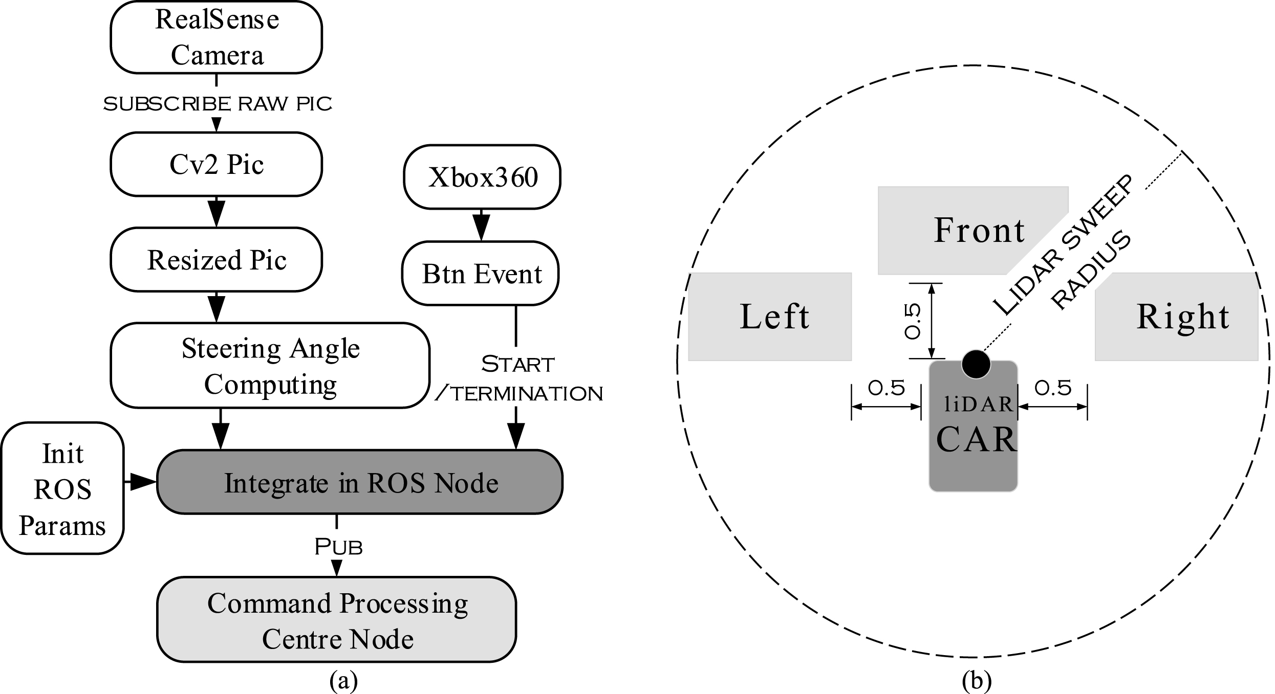
Design of deep learning mode (a) and area where liDAR collects the PCD (b).
Introduction of statistical method
By scanning of 360 degree to circumstance and the situation within 5 meters (Fig. 4) is acquired which is described as the PCD with different color (Fig. 6). The rectangle area 0.5 meter away from the car for counting the PCD in this paper is set to 2×1 (meter). by taking the method of checking and counting the number of PCD in front of car as well as the direction of left and right (Fig. 4), the raw data relevant with the steering decision is acquired.
Considering the size of the Traxxas car, so the Neato XV11 Laser liDAR with the scanning radius of 5 meters is enough to achieve the goal of obstacle avoidance.
The design of ROS package for liDAR evasion method
The raw point cloud is not qualified for computing the steering angle directly. So, Some preprocessing methods are needed like the method of cv_bridge() in openCV which is used for creating a greyscale image of birds view. Primarily, iterate over PCD in raw data. And then, map it to pixel. The next, convert pixel to ROS message.
After the procedure of preprocessing, the number of PCD needs to be counted in front of the car as well as the direction of left and right in birds view (Fig. 6), and then, the steering message is generated. The principle for decision message generating is demonstrated in Fig. 5. Meanwhile, the start and termination signals from Xbox360 are necessary. Otherwise, the format of the steering message is not qualified for the reason of missing velocity component. So, velocity messages from Command Processing Centre Node and steering messages from liDAR Node mix together to a completion. Finally, publish the message to Command Processing Centre Node. The design of liDAR Node is briefly demonstrated in Fig. 6.

Principle of making decision (a) and a test for checking the principle in low speed (b).
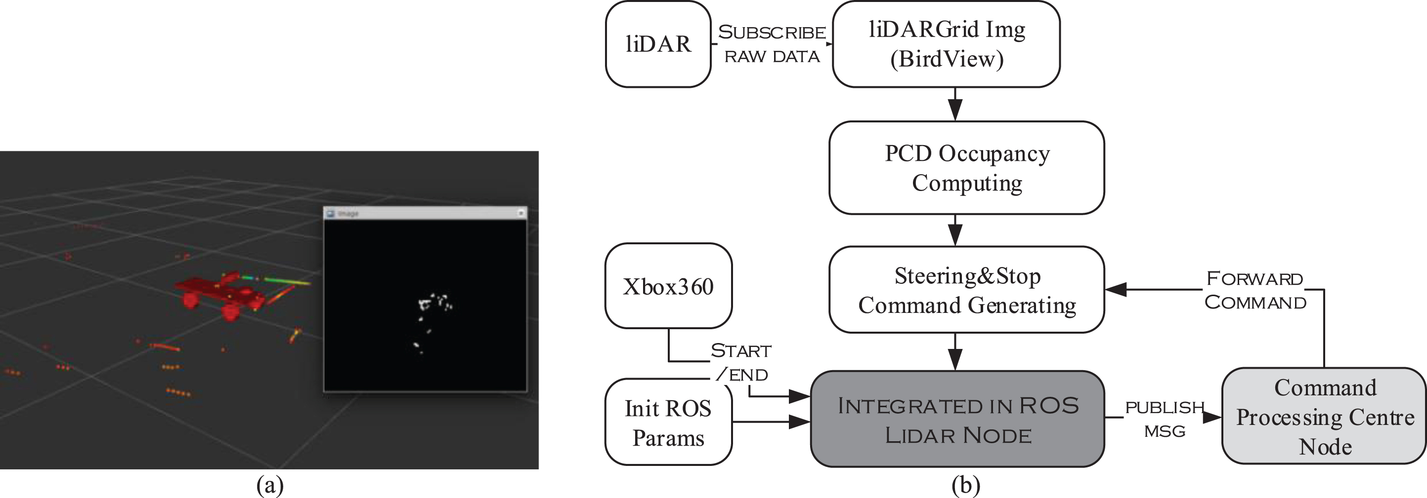
Birds view image which is transformed from raw data (a) and the design of liDAR Node (b).
As for Xbox360 controller in this paper, 10 of the control buttons on joysticks (Fig. 7) are chosen to throttle, initiate the CNN evasion mode, trim left, trim right, reverse & brake, cruise, launch the liDAR evasion mode, activate the data recorder and operate the car.
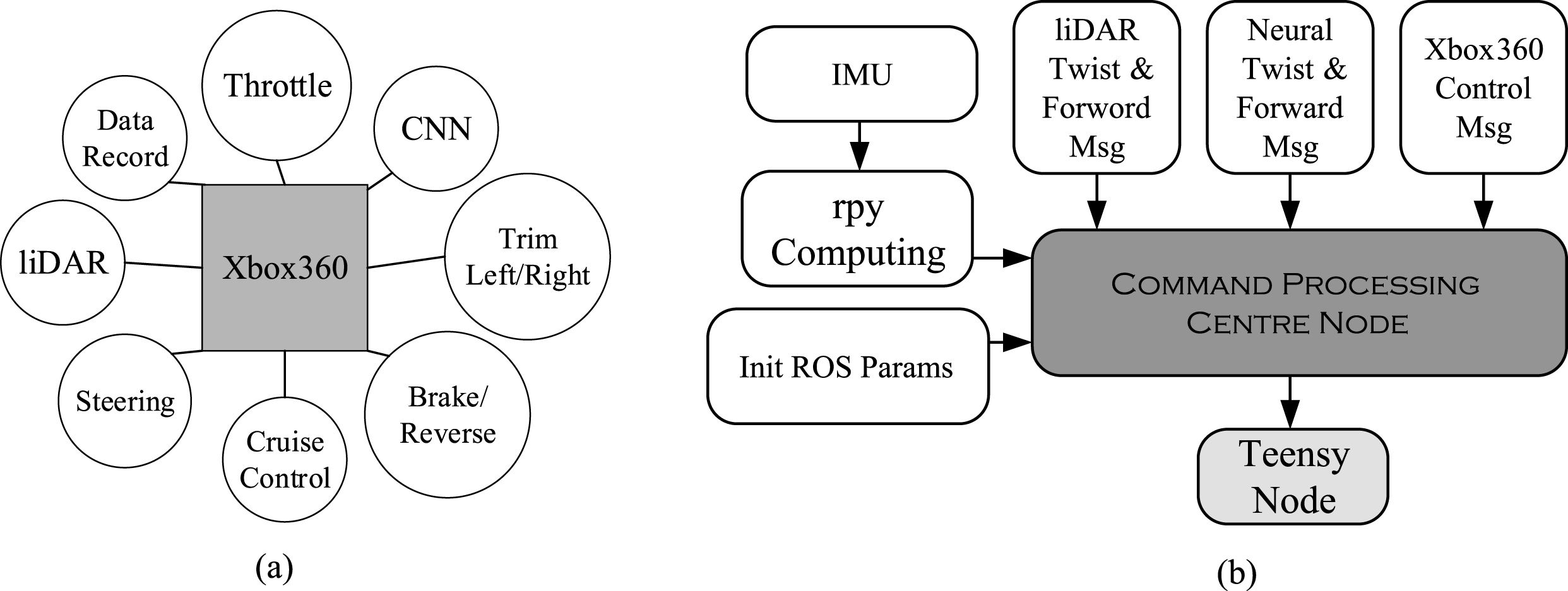
10 buttons in Xbox360 (joysticks) controller (a) and the design of Command Processing Centre Node (b).
The angle and magnitude are two of the parameters which are used to measure the action of joystick in Xbox360. the format of two parameters is not suitable for generating the steering and velocity messages for the reason that the raw message from Xbox360 is based on World Coordinate System (WCS), and it’s compulsory to transform the WCS to Cartesian Coordinate System (CCS) for being recognized by ROS. The equations of transformation are demonstrated in Equation (8).
The Command Processing Centre Node is responsible for processing all messages from each function module which involves the control message from Xbox360, the pose message from IMU and the twist message from liDAR as well as CNN.
As for message from IMU, get and transform it to the format of quaternion with the method of imuorientation(). Then, transform the quaternion to euler angle using euler_from_quaternion() and compute the value of rpy (roll, pitch, yaw). Finally, binding the data of IMU with the simulation model in RViz so as to archive the goal of pose estimation.
As for the message from the liDAR evasion mode, the velocity messages generated by Command Processing Centre Node attach to the steering message from liDAR for forming the qualified decision message to manipulate the car finally.
As to the steering messages from CNN, the procedure of processing the decision messages from liDAR is the same as the procedure of CNN’s which means the steering messages from CNN mix with the messages from Command Processing Centre Node to form the compositive message and publish to hardware (Teensy3.6).
With regard to the messages from Xbox360, the main workload includes the acquirement of the button event and the setting of relevant parameters and functions which involved the setting of cruise, control of velocity, initialization of throttle, the definition of steering & velocity & reverse, etc.
Finally, the qualified messages from Command Processing Centre Node are sent to Teensy3.6 with the method of rospy.Publisher(). The design of Command Processing Centre Node is briefly demonstrated in Fig. 7.
The design of data recorder
For the reason of limited recognition rate of CNN model because the image set acquired is limited, so it’s necessary to acquire more images for retraining the CNN model when the obstacle avoidance car is brought to a strange environment so as to enhance the success rate of obstacle avoidance.
Meanwhile, considering the efficiency of data collection and inconvenience of data storing in each car, so, a scheme about the data recording is constructed. The fundamental principle of the Data Record ROS Node is collecting the images from each car and storing them in PC which is equipped with high-performance GPU by transmission function in ROS. In this way, the time-consuming phase of training is shorten to a great extent.
The design of Data Record Node is same as the node design before. the primary step is to initialize the relevant parameters and functions like CvBridge() and XBox360(). Then, subscribe the raw messages which involve the RGB image, birds-view image from liDAR, and depth image from RealSense camera with the method of rospy.Subscriber(). Meanwhile, the messages from Command Processing Centre Node and Xbox360 are processed at the same time for generating the image label and initializing the Data Recorder mode. The design of Data Record Node is briefly demonstrated in Fig. 8 and the details are as follow:
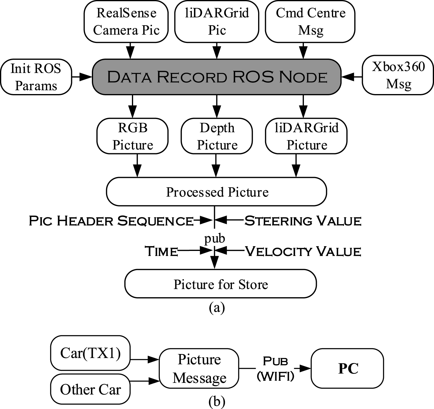
Design of Data Record Node (a) and data co-collection (b).
As to the decision messages from Command Processing Centre Node, the components of steering and velocity are extracted with the method of msg.wist().
With regard to the image messages from liDAR and camera, transform the format of the image to openCV message using bridge.imgmsg_to_cv2(). Then, generate the qualified format of label with the sequence of image header, time stamp, value of velocity and value of steering angle. Finally, transmit the image attached with the label to PC (Fig. 8) using the transmission function in ROS for retraining the CNN model.
As for the messages from Xbox360, update the status of button in Data Recorder Node with the method of controller.update() and acquire the button event to launch the Data Recorder mode with the method of controller.buttonEvents().
For the purpose of transplanting to the real electromobile in the future, Traxxas car (Fig. 9) was adopted as our object of research which was highly similar to the real electromobile in majority of essential hardware components and software function just as servo system and driver system.
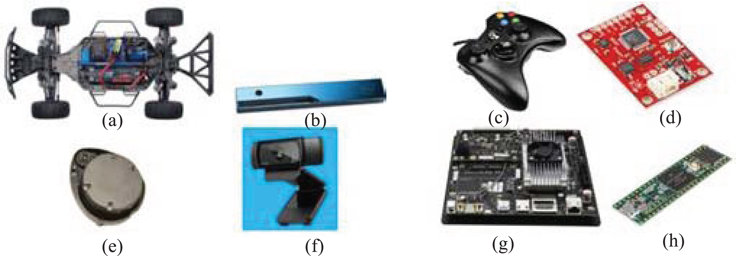
The core sensors of Intelligent Obstacle Avoidance Car. (a)∼(d): Traxxas car, Intel RealSense camera, Xbox360, 9 DoF razor IMU. (e)∼(h)Neato XV11 laser liDAR, Webcam, nVidia Jetson TX1, Teensy3.6.
In terms of sensor selection, 2D liDAR (Fig. 9) and Intel RealSense camera (Fig. 9) were taken into account which worked together to realize the aim of obstacle avoidance. Furthermore, IMU (Fig. 9) was adopted to monitor the moving posture and trajectory of obstacle avoidance car.
Apart from the IMU, nVidia Jetson TX1 (Fig. 9) which was used for enhancing the efficiency of matrix calculation in Deep Learning, Teensy3.6 (Fig. 9) which parsed the decision messages to analog signals so as to be recognized by Traxxas car, Logitech Webcam (Fig. 9) which was used to shoot the road condition ahead and transmitted the feedback (images) and Xbox360 (Fig. 9) which was used for initializing the car were taken into consideration. In extreme circumstances, special action must be taken by Xbox360 to gain the absolute privilege of control to the car for the purpose of security. Finally, all the core sensors were connected by 7 port USB hub. The hardware framework is demonstratedin Fig. 10.

Framework of hardware.
After accomplishing the node design of ROS, Tensorflow was initialized as well as all the function modes which involved the Xbox360 mode, liDAR evasion mode, CNN evasion mode. The Data Flow Diagram (DFD) of all nodes was acquired and briefly demonstrated in Fig. 11.

The rqt_graph which shows the relationship of each node when system was launched.
The CNN model which was trained with 10 thousands images archived a recognition rate of 97 percent (Fig. 12). For the sake of checking the success rate of obstacle avoidance and robustness, 60 experiments which included 20 tests for CNN mode, 20 trials for liDAR mode and 20 experiments for the co-decision of liDAR & CNN mode were conducted and the results demonstrated that the success rate of CNN mode came up to 90 percent and the obstacle avoidance rate of liDAR reached 90 percent as well. When two modes worked together to make the co-decision, success rate of 100 percent in obstacle avoidance was achieved (Fig. 13). The experiments also demonstrated that the trajectories of collaborative method based on CNN and liDAR had higher robustness compared with the method which adopted the solo technique or single sensor (Fig. 14) in cruisemode.

The recognition results of a random batch of images (100) when steering.
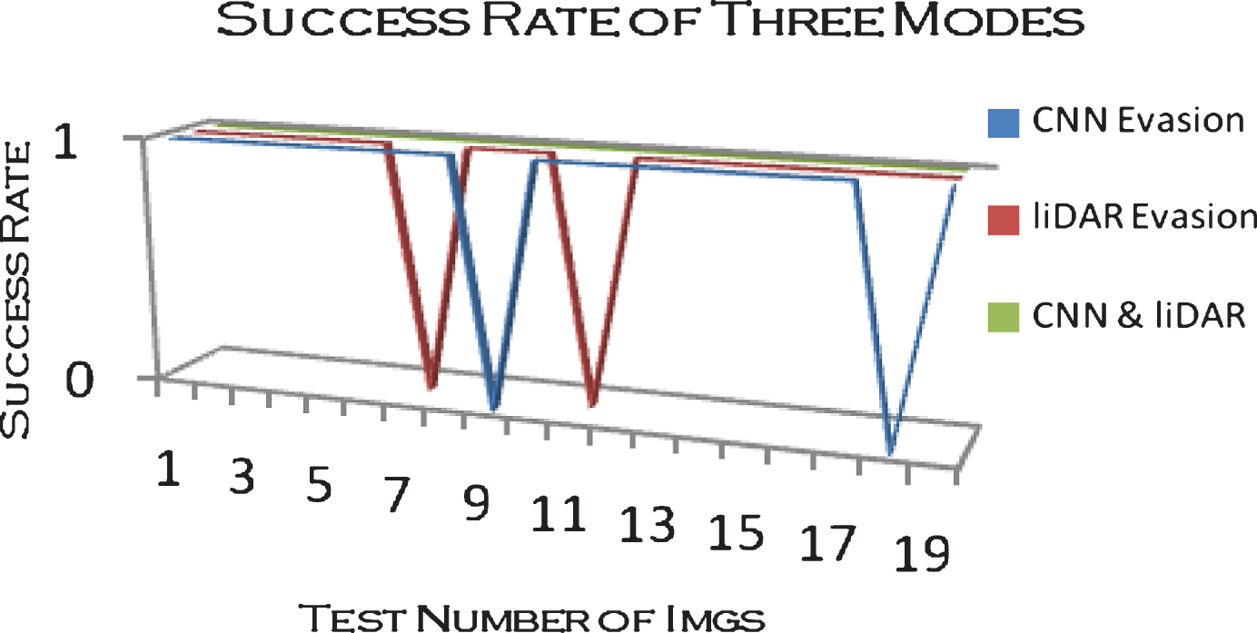
The obstacle evasion test of 3 modes.

Theoretical trajectories of CNN and liDAR in low speed (a) and 60 experiments of 3 modes in cruise situation (b).
Intelligence is the trend of future. The autonomous obstacle avoidance car is not our termination of research. Autonomous commercial car with high intellectualization is our destination. At the same time, the security of the network about the autonomous vehicle is crucial as well.
In view of this, future works which involve Simultaneous Localization and Mapping (SLAM) (e.g. ORB-SLAM [28] and [29]), global positioning based on GPS, and path plan will be accomplished. Meanwhile, Deep Learning and Reinforcement Learning will be applied into the rest tasks of autonomous car which covers the lane detection and tracking, pedestrian recognition, and Intrusion Detection & Prevention (IDP).
Footnotes
Acknowledgments
The research of obstacle avoidance car as well as its implementation are funded by Sci-Tech Support Plan and Application Base Plan of Sichuan Province, China [Grant Numbers: 2016GZ0343 and 2015JY0007].