
Abstract
3D Reconstruction has been an enduring problem in Image understanding and computer vision. There is an increasing interest on 3D information in the general public due to rapid development of 3D imaging techniques, marketing of 3D movies and games, and low cost of depth cameras. Numerous algorithms that have been proposed for performing 3D reconstruction using different variants of Iterative Closest Point(ICP) algorithm focusses mainly on reducing the computation time. The accuracy of 3D reconstruction is not taken in to consideration. An efficient, accurate, real time and active 3D reconstruction method using Kinect sensor is developed in this paper focusing on improving the accuracy of 3D reconstruction in less computation time. An Artificial Bee colony based ICP algorithm is proposed by incorporating several efficient variants of ICP algorithm. The proposed algorithm is intended to improve the accuracy and stability of the standard ICP algorithm. The performance of the proposed algorithm is satisfactory when compared with structured light technique and several ICP variants with respect to accuracy, complexity and computation speed.
Keywords
Introduction
The process of obtaining the three-dimensional information of an object or scene using two or more views has been a challenging task in computer vision. Active and passive methods are used for performing 3D Reconstruction. Active methods use numerical approximation approach to reconstruct and build the objects in scenario based on the model. It includes Structured light, laser range finder, and depth cameras. Passive methods, unlike active methods do not interfere with the object to be reconstructed. Instead, they use a sensor to analyze the 3D structure through image understanding. Active methods of 3D reconstruction provide many real-time applications and are faster than passive methods. Laser range scanners or structured light projecting systems is used for acquiring the images in active methods [19]. A known pattern is projected on the surface of the object and 3D information is extracted by simple triangulation technique. 3D models with high accuracy can be obtained in less time using active methods. Douglas Lanman elaborated the underlying concepts used for the design of 3D scanners using Structured light technique [18]. Various types of patterns used in structured light technique, camera and projector calibration methods and applications of 3D imaging techniques has been discussed in [27]. Structured light scanners uses a variety of patterns that are projected on the objects [8–12]. Imaging of wider surface areas are obtained by using multiple projectors [10].
Kinect sensor is an efficient tool for active 3D reconstruction which uses time-of-flight method to process enormous information in a short period of time. Kinect v2 captures information with greater precision even without visible light using an IR sensor. S. Izadi [22] et al. introduced Kinect fusion in which a real-time 3D reconstruction is achieved only with Kinect camera and hardware graphics. New methods have been proposed for simultaneously segmenting, tracking and reconstructing dynamic users with the background scene, which provided a greater level of user interaction. Soon-Yong Park [5] presented 3D reconstruction in which a stereo technique is used to obtain 3D model in different views and integrated using volumetric techniques. The matching is based on voxel classification which is accurate and has less computation, but it needs more geometric constraints. Yemez [20] proposed a passive method of 3D reconstruction using marching cubes algorithm. Robust camera calibration and sampled texture mapping resulted in recovery of objects with high speed. Abhik Maiti [21] used two dimensional images to reconstruct photo realistic 3D model using ball pivoting algorithm and poisson reconstruction. Indicator function is represented using marching cubes algorithm to extract the surfaces. Ball pivoting algorithm involves moving a ball of known radius around 3D points to create 3D meshes, however it is time consuming. Curless [13] proposed a method to create face models using image streams from different view points. Tools are described for face animation by exploiting the representation of facial dynamics using face graphs. This method can be used in industries for 3D reconstruction of point clouds with uniform density. Besl and McKay [1] introduced the Iterative Closest Point algorithm which is used for 3D registration. Numerous variants of the standard ICP have been developed for optimization of results in different applications. Ahmad Almhdie [24] used a method for 3D registration in medical imaging using ICP algorithm with comprehensive look-up matrix. Picky ICP involves rejection of all points which are previously estimated for each reference point, except the point having minimum distance. But this method is not suitable in noisy situations. Matrix based search is used for finding corresponding pairs for producing better estimation of transformation parameters. The speed of convergence and robustness are not affected by Gaussian and impulsive noise. It also introduced a comprehensive look-up matrix, which uses all the scene points to estimate the best correspondence pairs. Timothee Jost [23] used a technique for 3D registration using multiresolution ICP which is combined with neighbor search algorithm to achieve higher rate of convergence. Complexity has been reduced and matching quality is preserved by this method. Shun Ichi Kaneko introduced a method for matching 3D contours using ICP with M-estimation. This method involves extending the steps of ICP for optimizing an objective function through iterative estimation of weighing co-efficients. Rotation parameters are represented using quaternions in order to reduce the problem of orthonormality. Robustness to outlying data is achieved when appropriate initial positions are given. Matej Kopernicky presented a method to align point clouds of subsequent frames using KD tree based ICP [4]. This method uses matched SURF descriptors which are extracted from RGB images as an initial estimate. Low resolution of depth maps and constant amount of noise are the drawbacks which resulted in reconstruction with loss of details. Shaoyi Du [3] suggested a new ICP algorithm which involves isotropic scaling of point clouds using Expectation (E) and Maximization (M) algorithm. In E-step, point-to-point correspondence is developed whereas in M-step, scale transformation including translation and rotation matrices is computed. Isotropic scaling registration is used along with Gaussian model to produce better results. Zili Y I et al. proposed an algorithm for point search between two clouds by using a variant of Artificial Bee Colony (ABC) algorithm [28].
The proposed active method of 3D reconstruction using Kinect sensor is proved to be efficient than the structured light technique. This method uses Kinect v2 sensor for acquiring color and depth information. These information are obtained by positioning the object at different angles. The 3D point clouds are generated by combining these information. 3D SIFT descriptor is used to extract the keypoints from the point clouds. The keypoints extracted 3D point clouds are combined using ABC based Iterative Closest Point (ICP) algorithm. The standard ICP algorithm is modified by introducing Artificial Bee Colony algorithm in the matching step. The obtained 3D reconstructed model is better than that of structured light technique in terms of accuracy, complexity and computational speed.
The first part of this section introduces the Structured light method and the second part concentrates on the Kinect sensor and its application of 3D reconstruction using ABC based Iterative Closest Point algorithm.
3D Reconstruction using structured light method
3D reconstruction using Structured light technique is implemented using a projector and two cameras. Horizontal and vertical patterns of various sizes is projected on the object or scene and the pattern gets deformed based on the shape of the object. The deformed pattern is imaged using the left and right cameras similar to the stereo vision cameras. The cameras and projector should be perfectly calibrated. The depth information can be retrieved by comparing the projected and deformed patterns.
Figure 1 shows the overview of structured light scanning system.

Structured Light Scanning.
Binary or gray code encoding scheme is used to encode the information into sequence of patterns. These sequence of patterns is projected on the object using the projector. Both the camera and projector is calibrated to compute the intrinsic and extrinsic parameters. Once the projector and the cameras are arranged, the lighting needs to be considered. The pixel’s intensity values between the first two projections are compared to determine the pixels in the shadow regions. The pixels in the shadow region are neglected. The Images captured using the camera are finally decoded and thus a mapping between the two camera pixels which corresponds to the same 3D point is derived. 3D scanning methods are mostly based on triangulation [17]. The 3D point is finally computed by triangulating the mapped pixels.
The proposed method of 3D reconstruction shown in Fig. 2 uses Kinect v2 sensor for acquiring color and depth information. These images are captured by positioning the Kinect sensor stationary and tilting the object at various angles. Four sets of images containing the depth and color information are acquired, two sets of which are combined to produce a point cloud. Hence two different point clouds of the same scene or object is produced. Keypoints are extracted from both the point clouds using 3D SIFT descriptor. The keypoint extracted 3D point clouds are merged using ABC based Iterative Closest Point (ICP) algorithm to obtain the 3D reconstructed model. The standard ICP algorithm is modified by introducing Artificial Bee Colony algorithm in the matching step as shown in Fig. 3. The Proposed method excels the structured light technique and several ICP variants with respect to complexity, accuracy and computation speed.
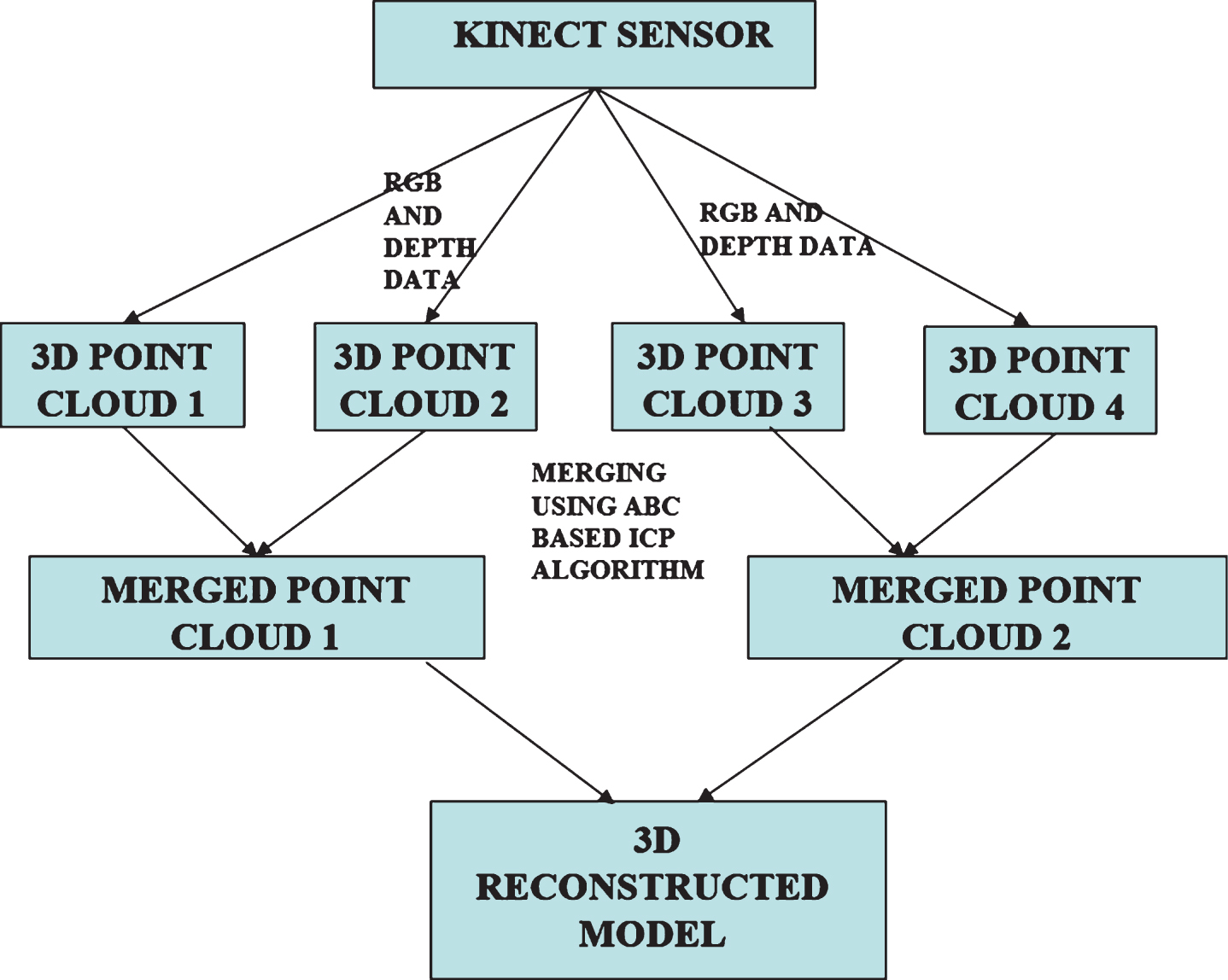
Proposed 3D Reconstruction Technique.
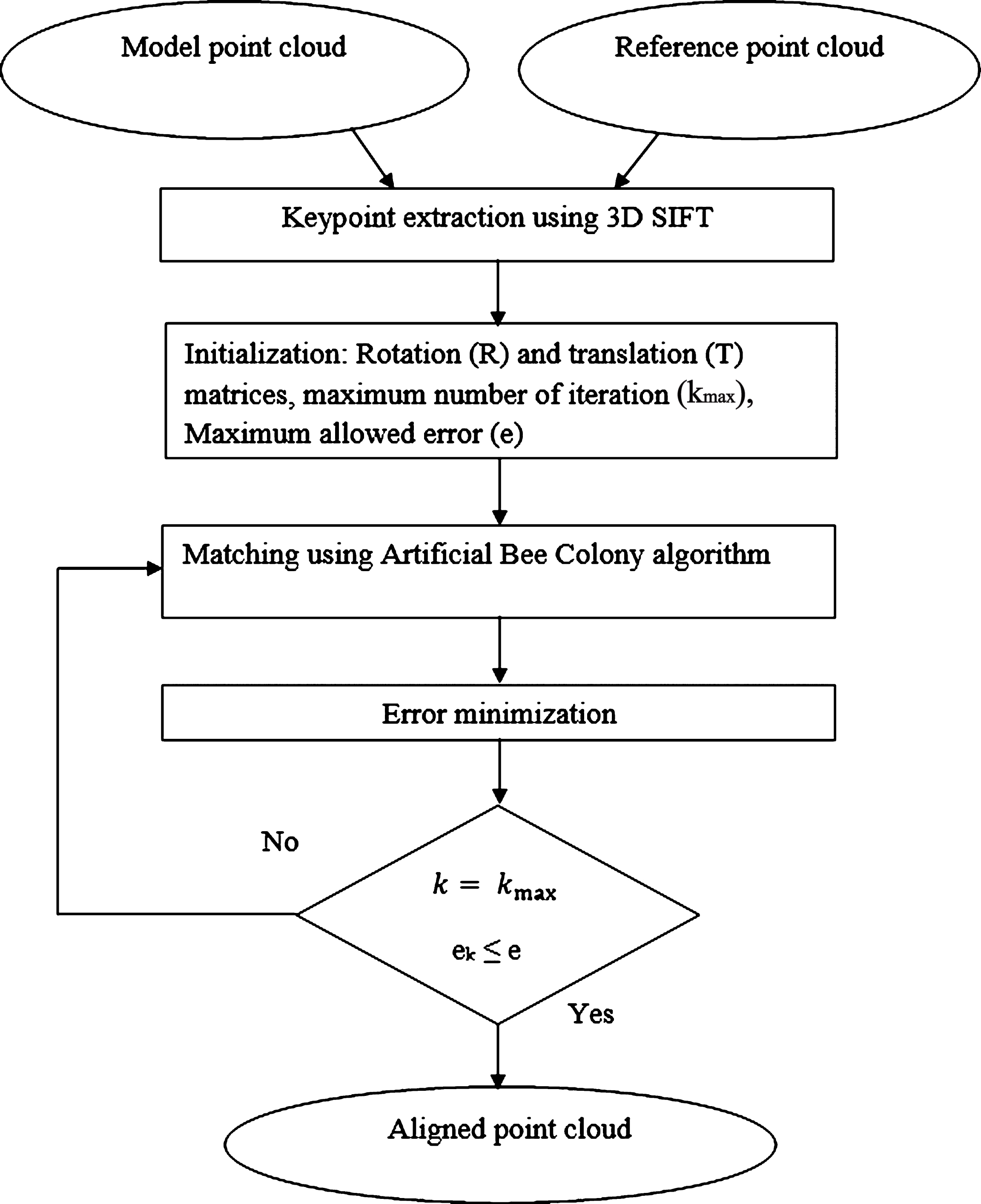
Flowchart for ABC based ICP.
Kinectv1 sensor is a great development by Microsoft, which is succeeded by Kinectv2 that has greater resolution and uses the time of flight technique to capture both color images and depth images. Time of Flight device works by measuring the time taken by light waves to travel from the sensor to the object and back to the sensor. Kinect sensor consists of a color sensor that captures three channel data with a resolution of 1920x1080 pixels and an IR emitter that emits infrared rays which is read by the depth sensor to produce depth maps with a resolution of 512x424 pixels. It can be operated with a range 0.5 to 4.5 meters both in indoors and outdoors. It is one of the low cost sensor used for real time 3D reconstruction, motion capture, object recognition, virtual reality, etc.
Iterative closest point algorithm
In order to make 3D reconstruction successful, the 3D point clouds obtained from Kinect sensor should be registered accurately. The most suitable algorithm for merging point clouds is Iterative closest point, proposed by Besl and McKay [1].
The objective of this algorithm is to find the closest point in an iterative manner, by minimizing the error between the chosen points. Every iteration involves selection of closest point and calculation of transformation in order to minimize the error. The basic steps in an ICP algorithm are Initialisation, Input filter, Matching, Output filter, Error minimization and Assessment/Enhancement. The various steps can be modified to achieve higher accuracy and improved speed of convergence making it suitable for real time applications, like 3D scanning and model basedtracking [26].
A scale transformation matrix can be initialized along with other transformation which is used in matching process for accurate alignment of point clouds [16]. This approach is useful when dealing with point clouds of different sizes. Standard ICP involves its own estimation which results in weak robustness and loss of data. Kalman filter which uses quaternion basic algorithm, when iterated with ICP produces robust pose tracking. Scale Invariant Feature Transform (SIFT) can be used to estimate initial parameters as it provides accurate and stable 3D information. It is robust as it reduces the calculations which results in less computation time.
3D SIFT
Scale Invariant Feature Transform is a feature descriptor used for extracting the keypoints from an image (7). The main significance of this descriptor is its invariance to images of different rotations, illumination, scale and viewpoint. In this work, as point cloud data acquired from Kinect is used for performing 3D reconstruction, 2D SIFT is replaced by 3D SIFT for extracting the significant keypoints. The principal curvature of point data plays a key role in 3D SIFT descriptor. 3D SIFT involves Keypoints detection, orientation and Descriptor representation[14, 15].
Keypoint Detection
Keypoint detection involves convolving the point cloud P(x, y, z) with the Gaussian kernel G(x, y, z, k) to obtain the scale space.
where
The scale space at various levels are generated by varying the factor k and the Difference of Gaussian is obtained by calculating the difference between these levels.
Scale space search is performed by comparing a pixel with its neighbors in the current and adjacent scales. The maxima or minima point in the scale space search is identified as the keypoint. Thresholding is done to remove the points having low curvature values.
Keypoint Orientation
A stable orientation is assigned to each keypoints by calculating the 2D weighted histogram between the keypoints and its center. The magnitude, direction and the angle associated with each keypoint is calculated.
2D weighted histogram is represented by grouping θ and Φ in to bins. Dominant orientation such as the azimuth and elevation is represented by the peaks in 2D histogram.
Descriptor representation
Every detected keypoint is represented by its location, scale and aligned angle. Rotation Invariance of the descriptor is guaranteed by rotating the neighborhood around the keypoint in the dominant orientation. This is performed by multiplying the points in the neighborhood by the following matrix.
where Pi represents the points in the neighborhood region of the keypoint.
Two point clouds from different views are obtained from Kinect sensor. One is kept as reference and other is transformed to match the reference point cloud. Firstly, the initial parameter values of rotation, transition, maximally allowed error and number of iterations are chosen. This initialization should be done properly to get accurate results. The two point clouds can be drawn to the same referential plane as proposed by Ridene [2].
MATCHING
The model points should be matched with the reference point clouds. The prime objective of this step is to find the closest point of all the model points to the reference point clouds. The closest point from both the point clouds is calculated using
where R denotes the rotation matrix and t denotes the translation matrix; Nm and Np represents number of points in model point cloud and reference point cloud respectively.
In this paper, Artificial Bee Colony algorithm is used for matching two point clouds. The intellectual performance of honey bees is incorporated in this algorithm. Each point in the model point cloud is considered as a bee colony and the points in the reference point cloud act as food sources. The prime solution involves matching each bee colony to a food source using three types of bees namely employed, scout and onlooker bees. Randomly X food sources are chosen for a particular bee colony (here X = 5). The employed bees recover the location of food source by searching in the nearby X food sources and shares its search results with the onlooker bees. The Scout bees perform searches throughout the reference point cloud. Each bee searches for the best food source suitable for a particular bee colony based on similarity measures. Similarity measures include photometric properties such as intensity, color and texture and geometric properties such as principal curvature and surface normal. Geometric properties suits better than photometric properties for finding correspondence between 3D points. Hence geometric are considered as the necessary information for 3D point cloud data. In this paper, principal curvature and distance measure is used to calculate the degree of matching. This algorithm offers the best order to find the correspondent point pairs.
Matching using ABC algorithm
Error minimization
The objective function is defined by the error metric and is minimized in every iteration of the algorithm. Two metrics that are commonly used are point to point and point to plane minimization. Point to point minimization sums the squared distances of model points to reference points.
Point to plane minimization sums the distances of model points to the tangent planes in which the matched reference points reside.
where n i denotes the estimated tangent normals at the ith model point.
A closed form solution exists for the minimization of the point to point error metric which is based on singular value decomposition or quaternion formulation. The point to plane error metric has a closed form solution after linearization of the rotation matrix R. In the error minimization step transformation matrices are calculated as per the equation.
This step involves comparing the error with ek, which is maximally allowed error and checking whether the iteration has reached Kmax, which denotes maximum number of iterations. Iteration is repeated until the error is small or maximum iteration Kmax reached.
Error map can be created as it does not affect ICP. This map is created and at the time error minimization process gets started. This map is useful for comparing purposes so that improvements can be done if needed.
Experimental validation
The experimental setup used in structured light technique consists of a projector and two cameras [25]. A total of 42 right images and 42 left images are acquired by projecting horizontal and vertical patterns on the object. Stereo matching is performed to the best pair image and the matched points are triangulated to give the 3D reconstructed points [6]. The 3D model is viewed in Meshlab software.
The fringe projected input images obtained by projecting the pattern and the 3D reconstruction results are shown in Figs. 4 and 5.
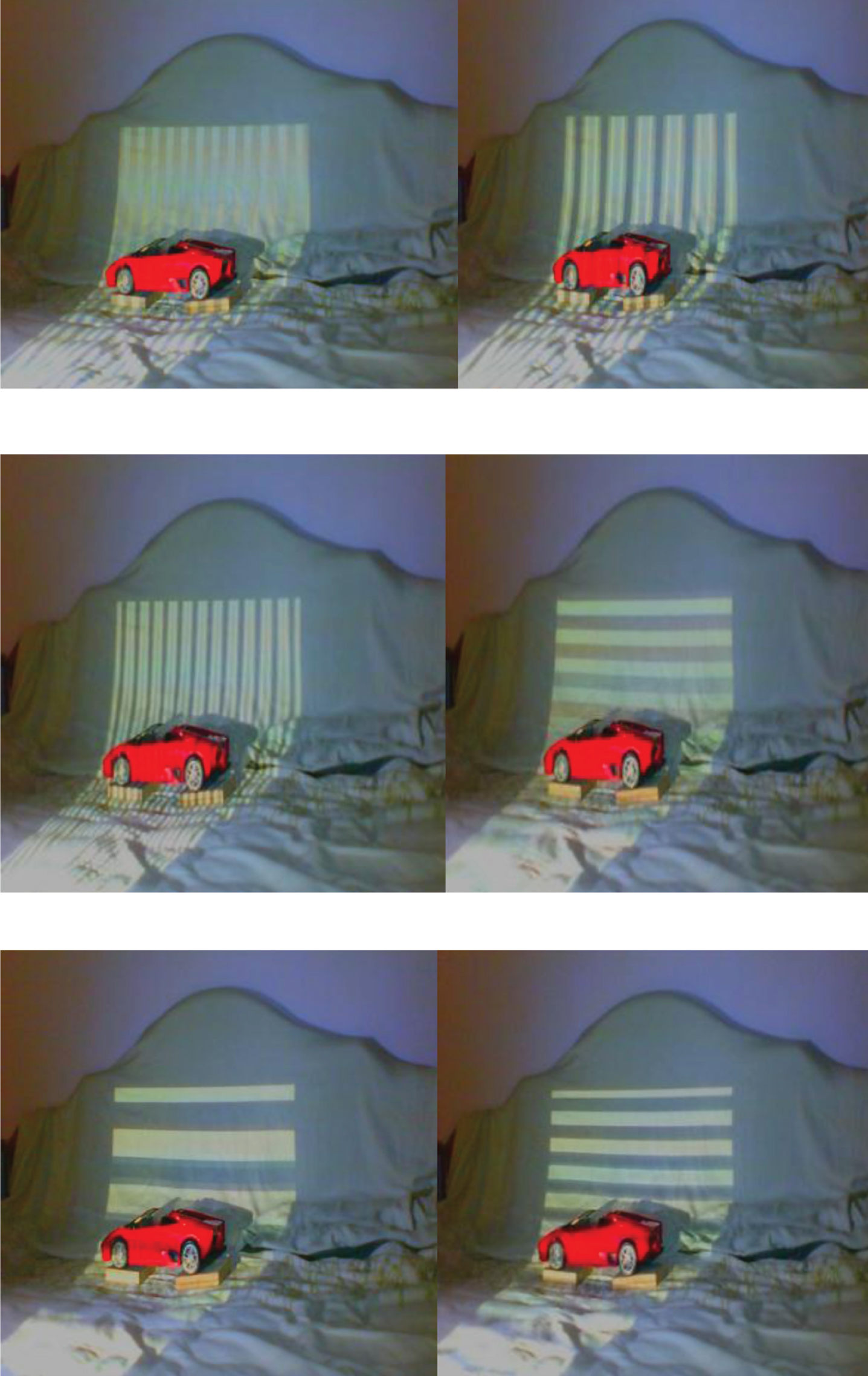
Fringe projected input images.
Reconstructed 3D model.
In the proposed work, Kinect v2 sensor is used to capture the color and depth information at various tilt angles. These information are combined to form four 3D point clouds. Each pair of 3D point clouds are merged using modified Iterative closest point algorithm which is further combined to form accurate 3D reconstructed model.
The proposed method gives better results than the structured light technique in terms of accuracy and complexity. The proposed method has been tested for different objects and scene and has been simulated using Matlab2017b software on Windows platform in i7 processor.
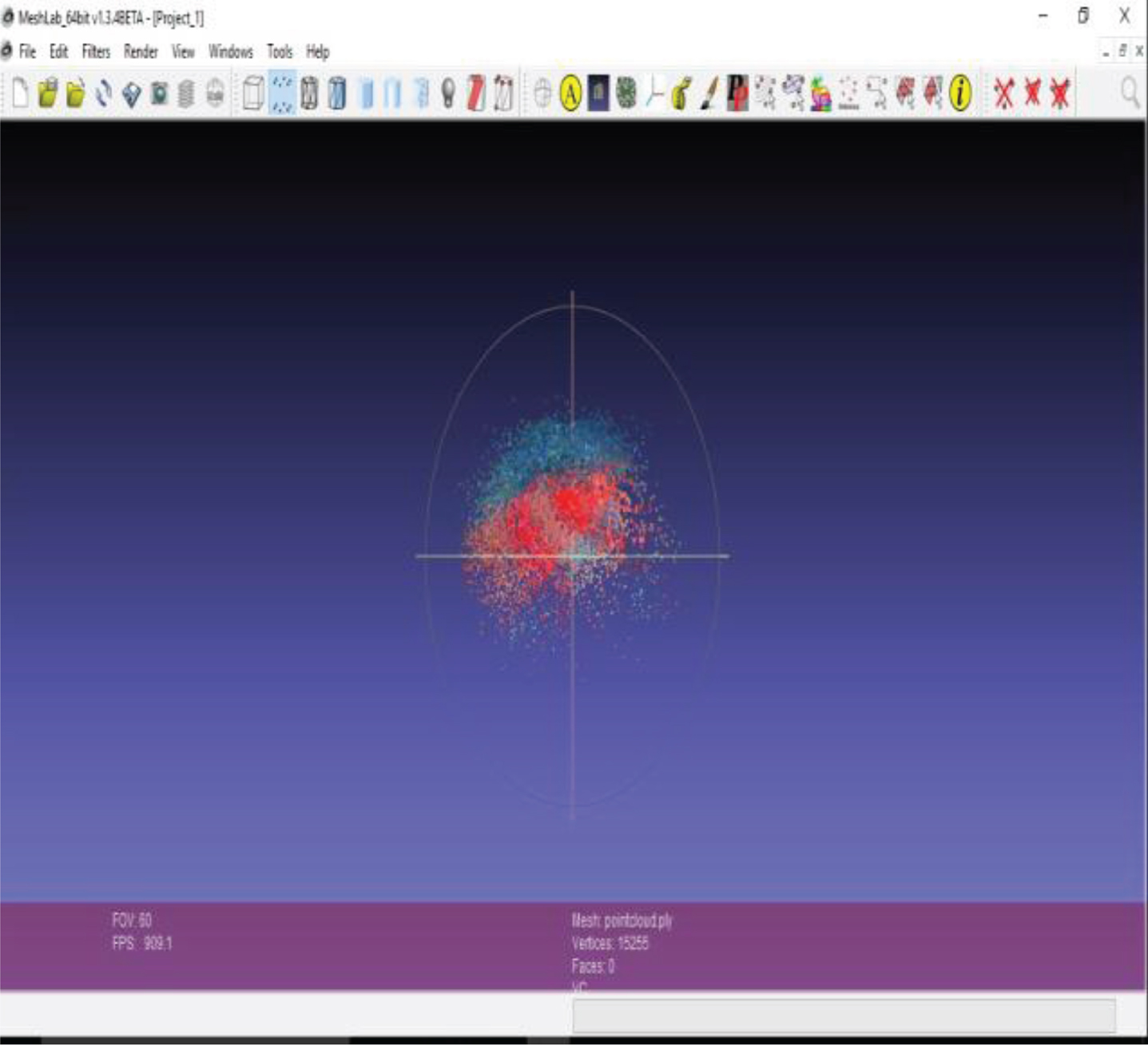
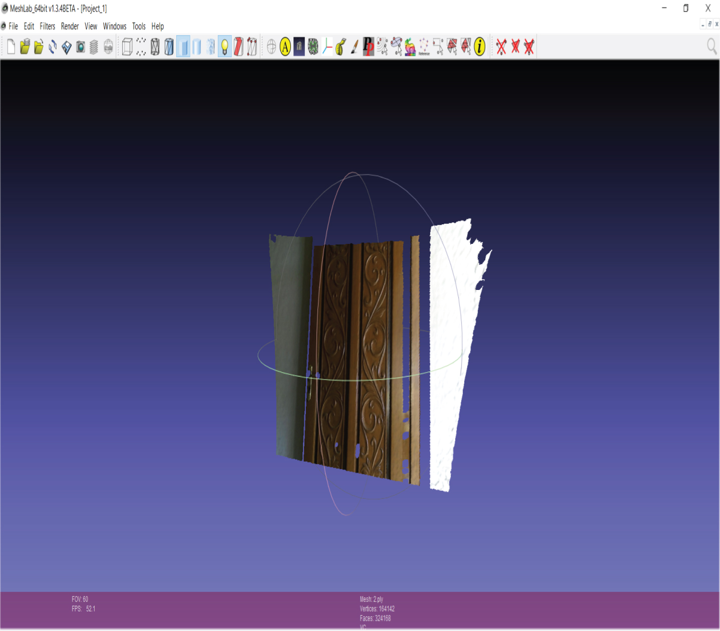
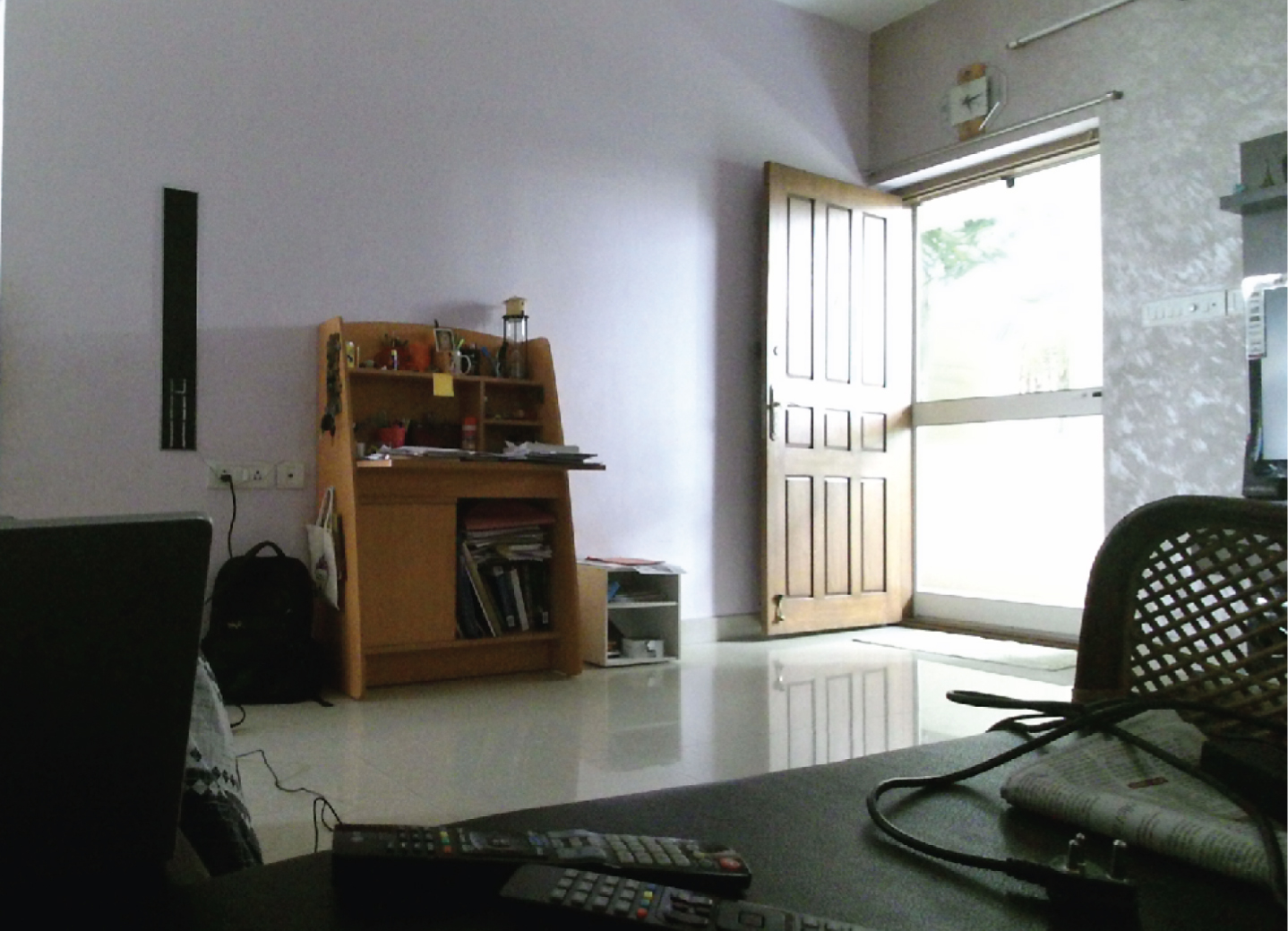
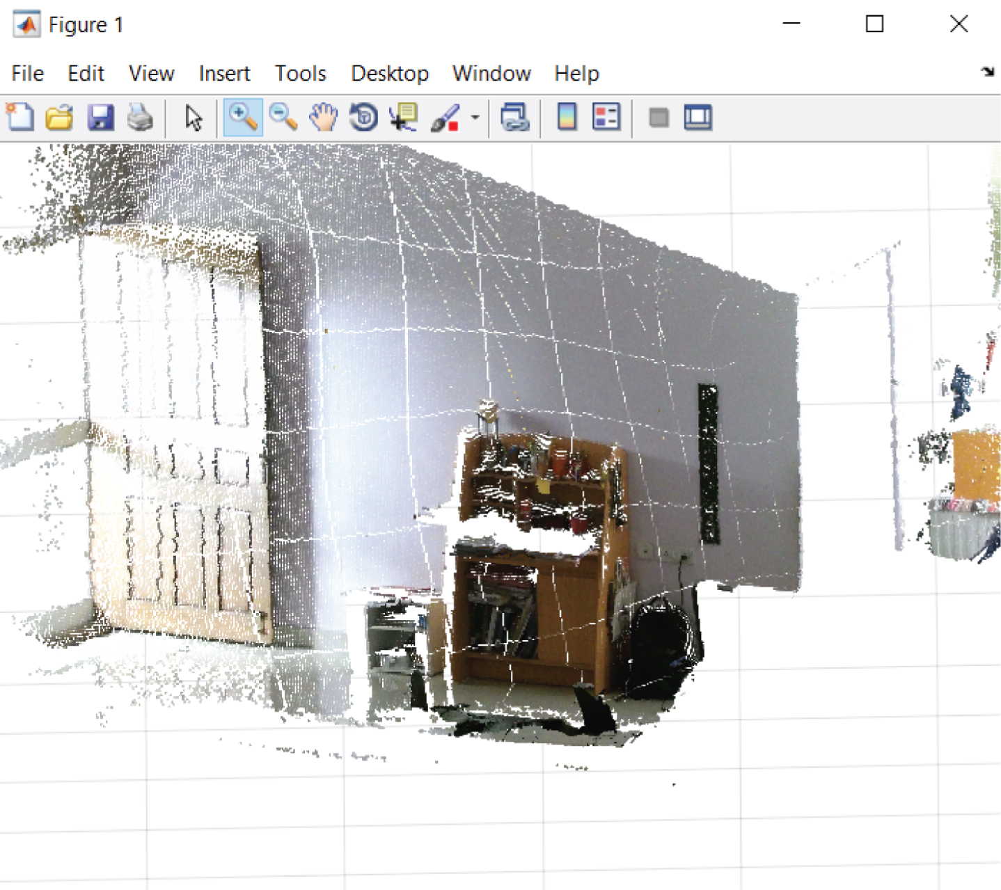
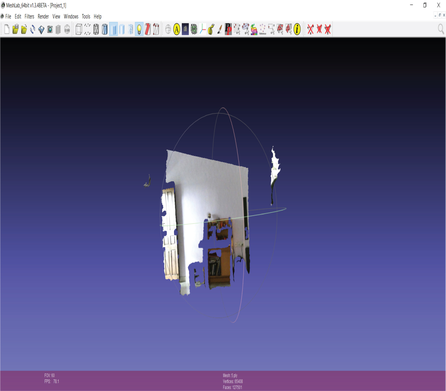
Figure 6 shows the input color image captured using Kinect v2 sensor. Figures 7–10 shows the point cloud generated at different angles. Since 3D SIFT is applied to extract keypoints, the number of points used for merging is limited, and the proposed 3D reconstruction method produces accurate results. Artificial Bee Colony algorithm is introduced in the matching stage of ICP algorithm to reduce the computation time. Figure 11 shows the final 3D reconstructed model in Meshlab.
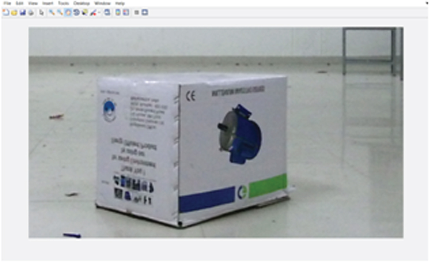
Input color image 1.
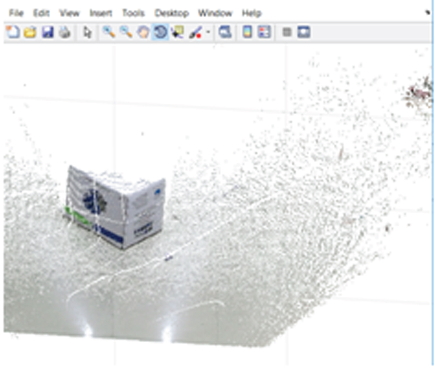
Point cloud 1 for input image 1.
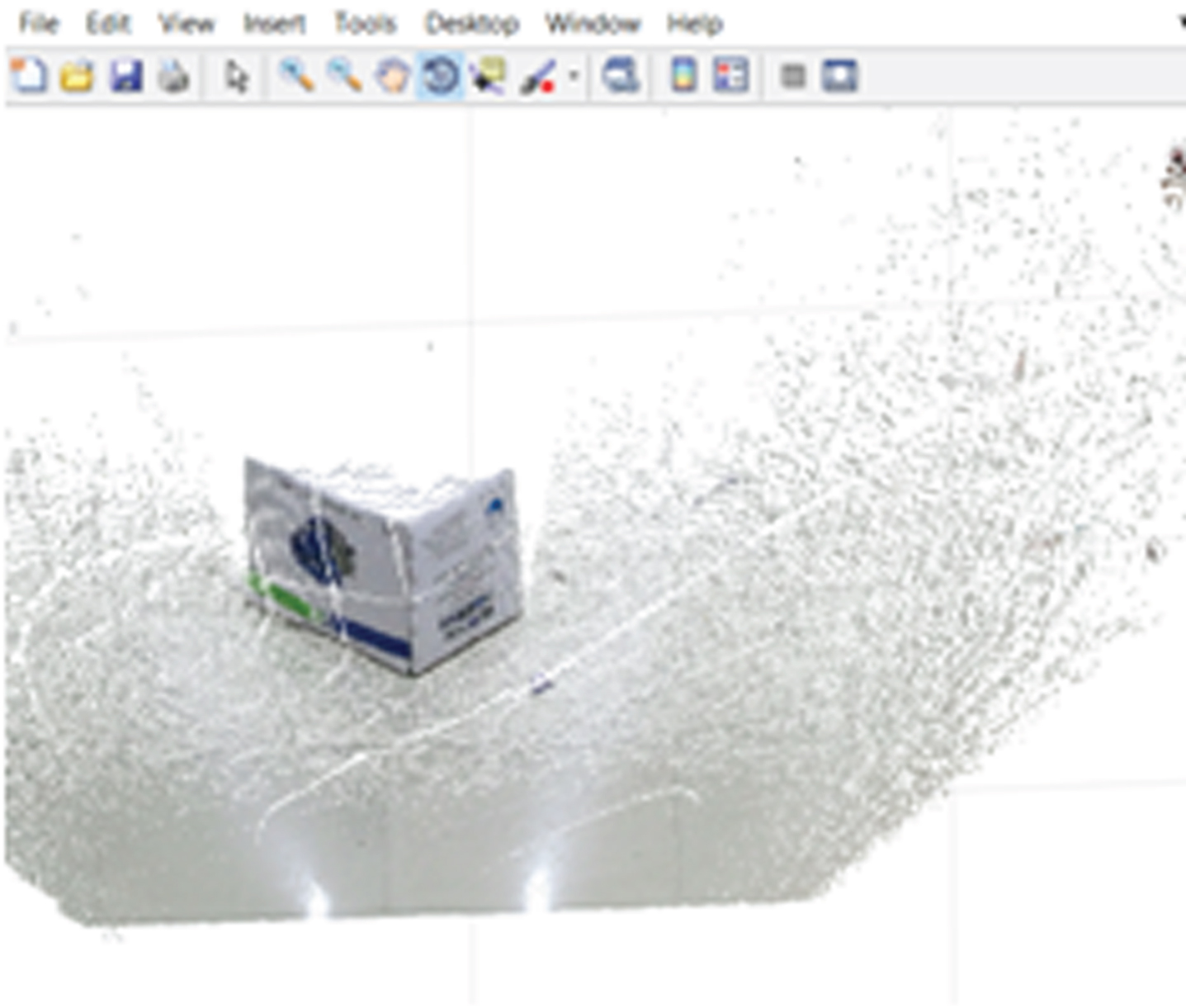
Point cloud 2 for input image 1.
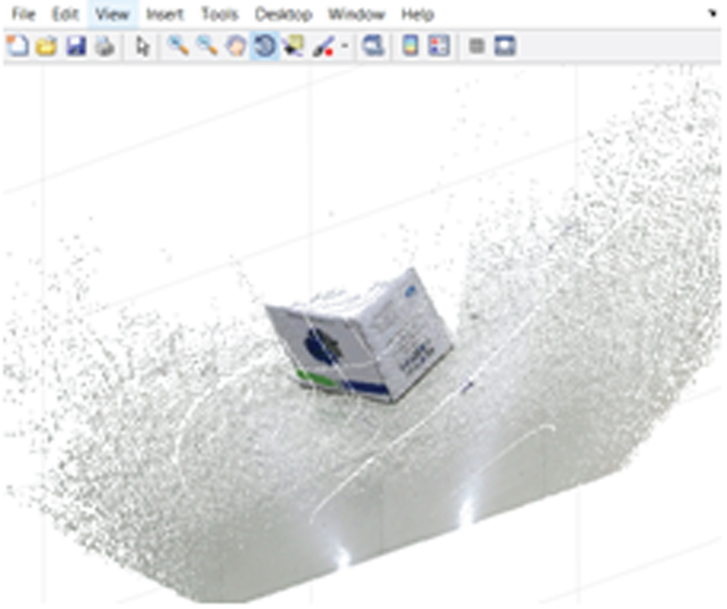
Point cloud 3 for input image 1.
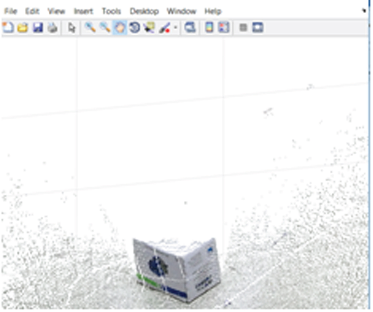
Point cloud 4 for input image 1.
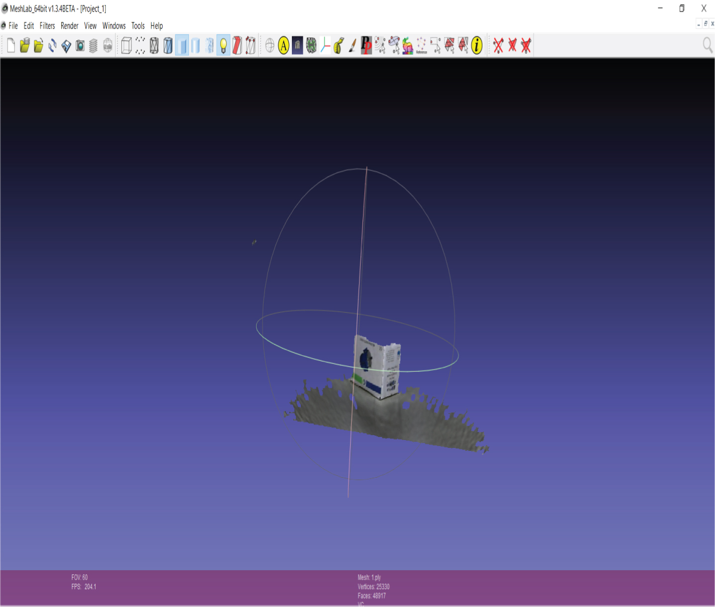
3D reconstructed image 1.
Figures 12–14 shows the input, point cloud and 3D reconstructed images respectively. Figures 15–17 shows the set of images for a scene involving more objects. It is inferred that the results are more accurate and perfect for even surfaced objects.
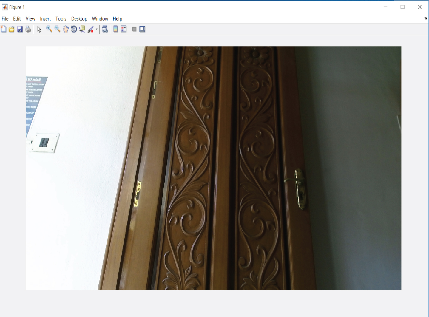
Input color image 2.
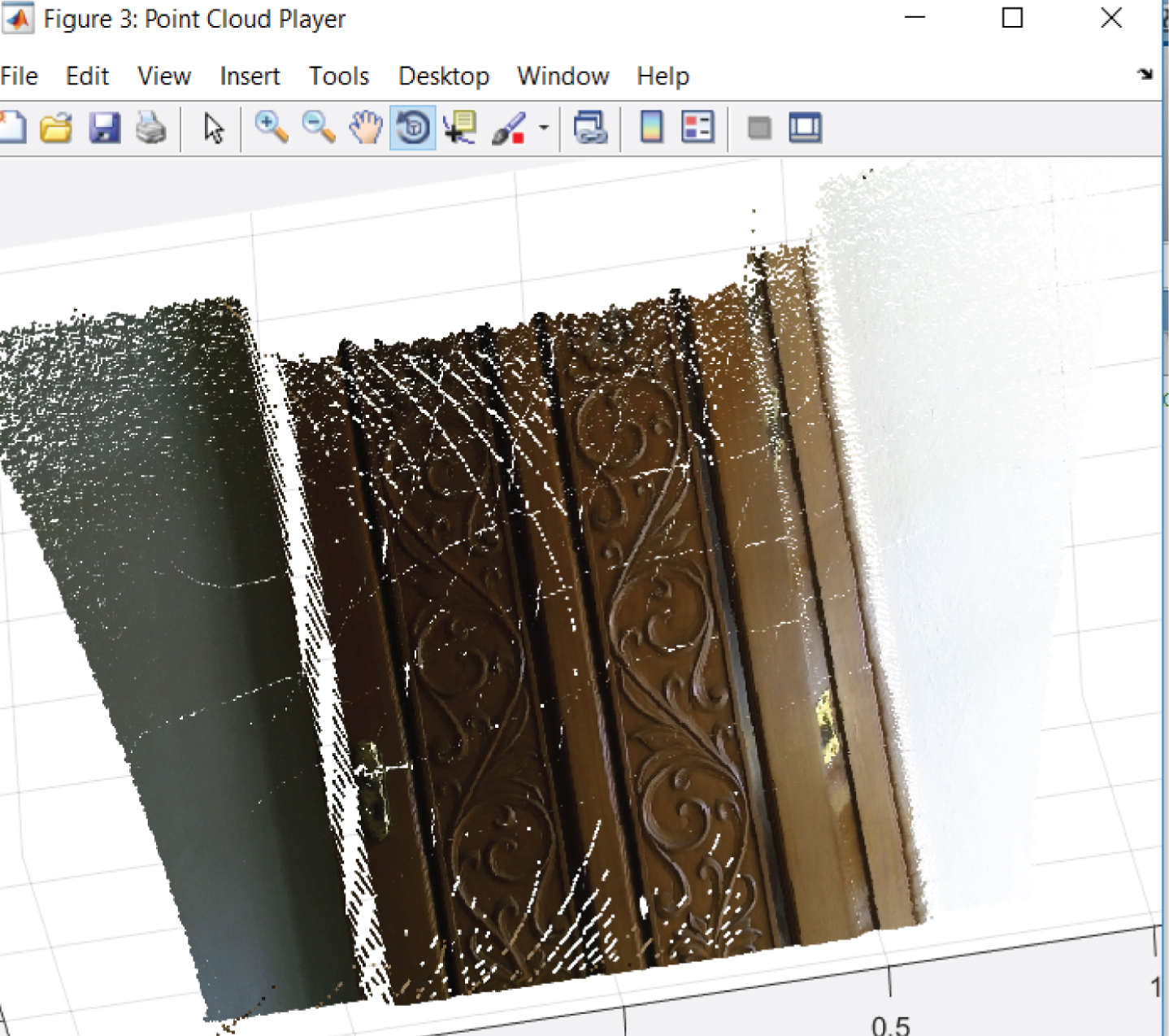
Point cloud for input image 2.
3D reconstructed image 2.
Input color image 3.
.Point cloud for input image 3.
3D reconstructed image 3.
The model obtained using Structured light method has many holes and it is not perfectly reconstructed, whereas in the proposed method the reconstructed model gives better visualization. Also the proposed method has less complex experimental setup.
The proposed method is compared with structured light technique with respect to the computational time and is given in Table 1. From the table it is observed that the proposed method consumes very less time say 18 seconds. The experimental setup used in Structured light technique is complex when compared with the proposed method and camera calibration is also performed in structured light technique, which increases the computational time. Whereas in the proposed method camera calibration is not necessary. The proposed method uses 3D SIFT descriptor to reduce the unnecessary points in the point clouds and also it uses ABC algorithm for matching the points in the point clouds thus reducing the overall computational time.
Comparison of Computation times between 3D reconstruction using structured Light Technique and Proposed algorithm
The computation times and the number of iterations required for convergence for different variants of ICP is tabulated in Table 2. The proposed ICP method is compared with the standard ICP and KD tree based ICP. It is inferred that the proposed method requires less computation time when compared with other methods and this is because of the fact that the proposed method uses only the keypoints for reconstruction. Even though the total number of points used for merging is reduced, all the points considered provides useful information for performing 3D reconstruction and hence the accuracy of the obtained model is also increased compared to other methods which focusses only on reducing the computation time. The proposed method also converges in minimum number of iteration. Three different scenes are acquired, each with different levels of details. The scene with less information converges at a faster rate when compared with the scene with more details. The computational time is also decreased for less detail scenes.
Comparison of Computation times and Number of Iterations between variants of ICP and Proposed algorithm
The registration error is calculated using
where P is the total number of corresponding points, R and t denotes the rotation and translation parameters.
Figure 18 shows the registration error plotted with respect to the number of iterations. The registration error is calculated for the proposed ABC based ICP and is compared with KD tree based ICP and standard ICP. The error is less for ABC based ICP when compared with the other two methods. As the number of iteration is increased, the error between the reference and model point clouds is decreased.
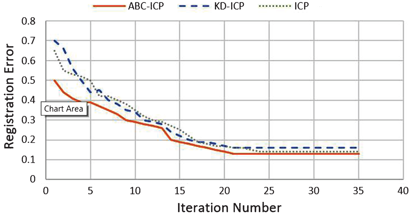
Registration error for ABC based ICP, KD tree based ICP and standard ICP with respest to the number of iterations.
Due to environmental conditions and various other factors, the data is subjected to different types of noises. The performance of the proposed algorithm under the influence of noise is tested by adding Gaussian noise with different standard deviation to the original data. This is done by converting all points from the cartesian coordinate to spherical coordinate and finally converting back to cartesian coordinate.
Figure 19 shows the registration error plotted with respect to the standard deviation of Gaussian noise. The registration error is calculated for the proposed ABC based ICP and is compared with KD tree based ICP and standard ICP. The registration error is less for ABC based ICP when compared with the other two methods. As the standard deviation of noise is increased, the error between the reference and model point clouds is increased.
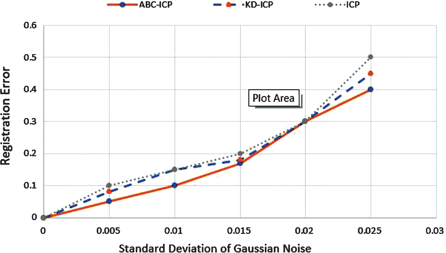
Registration error for ABC based ICP, KD tree based ICP and standard ICP with respect to the standard deviation of Gaussian noise.
Thus the proposed method of 3D reconstruction using ABC based ICP agorithm is efficient than the structured light technique and other variants of ICP. The objects in the scene are perfectly reconstructed as the algorithm uses only the keypoints for merging the point clouds. Necessary keypoints are selected using 3D SIFT and other points are removed. This reduces the total number of points used for reconstruction and thus reduces the computation time. The computational time is further reduced by introducing ABC algorithm in the matching step of ICP. The proposed algorithm is compared with other methods based on the accuracy, computation time and registration error. The algorithm reconstructs accurate 3D models with minimum registration error in less time when compared with other standard methods. Further, the experimental setup is relatively simple, as the method uses Kinect sensor to acquire the point clouds. Thus, the proposed method of 3D reconstruction outperforms other active methods with respect to accuracy, computational complexity and time.