
Abstract
The traditional Gauss-Newton iterative method is highly dependent on the initial value when locating the multimode GNSS receiver. If the difference between the initial value and the true value is higher, the algorithm has the problem of increasing number of iterations, and the algorithm lacks the self main monitoring process of the GNSS receiver, which leads to a great reduction in the positioning accuracy. A high precision multi-mode GNSS positioning algorithm is proposed. It is based on the composition and working principle of multimode GNSS multimode receiver, and the pseudo distance positioning distance is obtained by using GNSS multi constellation combined location algorithm. It uses a direct algorithm without initial value and iteration through the new algorithm of high precision positioning. After linearizing the pseudo range location distance equation, the user’s general position is calculated. After the pseudo range location distance equation is carried out in the general position of the user, the user’s position correction is calculated by weighted least squares, and the exact location of the user is obtained. The receiver autonomous integrity monitoring (RAIM) algorithm based on the least square residual method of GNSS receiver is used to realize the self-improvement monitoring of GNSS, and to further improve the precision of the multi-mode GNSS positioning algorithm. Experimental results show that the proposed location algorithm has high location accuracy and stability.
Keywords
Introduction
Since the steady progress of the construction of BDS and Galileoleo systems, the application of the multimode GNSS data processing method has become the research hot spots in all fields, especially in the satellite navigation system [1]. Its high precision, global, and real-time characteristics have been paid attention to by the satellite navigation system, which are widely used in the world, and opening a new era of navigation. The current research results showed that the integrated multimode GNSS system can effectively improve the reliability and stability of GNSS positioning, especially in areas such as mountain areas, urban canyons, and so on [2]. The traditional Gauss-Newton iterative method is highly dependent on the initial value in the positioning process of GNSS receiver. If the difference between initial value and true value is higher, the algorithm has a problem of increasing number of iterations, and the algorithm lacks the process of independent monitoring of the GNSS receiver, which leads to the problem of the multimode GNSS positioning precision greatly reduced. To solve this problem, a high-precision multimode GNSS location algorithm is proposed in this paper to achieve high-accuracy positioning of multi-mode GNSS receiver.
Simulation of High precision multimode GNSS Positioning algorithm
The composition and working principle of multimode GNSS receiver
The specific process of multimode GUSS receiver [4] is acquisition, tracking, bit synchronization, bit extraction, frame synchronization, extraction of satellite parameters, satellite position speed calculation, and user position speed calculation. First, the receiver makes up for the satellite signal. After tracking the satellite signal, the multimode GUSS receiver can be measured to settle according to the positioning settlement scheme [5], which can calculate the longitude, dimension, height, speed, time and other information of the user’s location. The composition and working principle of multimode GUSS receiver, receiver function module, hardware and software architecture are the necessary parameter indicators of multimode GUSS receiver.
The multimode GUSS receiver [6] receives satellite signals through the antenna unit. After the signal is amplified by low noise, the intermediate frequency signal is output through two frequency conversion, low pass filter, medium frequency amplification, and automatic gain control (AGC). The intermediate frequency signal is quantized by A/D, the signal is processed by A/D, pseudo distance measurement is obtained by solution expansion and conciliation [7]. Based on this, the location, speed, clock error and clock error rate of users were calculated, and the navigation business under high dynamic conditions was implemented. The block diagram of its composition is as shown in Fig. 1.

Structure diagram of multimode GNSS receiver.
The antenna element is composed of active antenna, passive antenna, acoustic meter filter and low noise amplifier (LNA) [8]. The satellite signals of different frequency points need an independent antenna. The function of the antenna is to transform the very weak electromagnetic wave energy of the satellite signal into the corresponding current. The sound meter filter is to filter out the external interference signal and suppress the frequency of the cross harmonic mirror, while the LNA is to amplify the signal and improve the signal to noise ratio.
The receiving and processing module is composed of a radio frequency receiving circuit and a baseband acquisition and processing circuit. The radio frequency receiving circuit is composed of filter, amplifier, down converter and wood vibration source. It is responsible for amplifying, filtering, down conversion to intermediate frequency signals received from the antenna, to ensure stable high gain and make the power of the intermediate frequency signal in the range required by the baseband acquisition. The baseband acquisition and processing circuit is composed of A/D, FPGA, memory, DSP and so on. It uses 8 bit A/D for intermediate frequency sampling, and the signal channel uses FPGA. Its function is to retrieve, pull and track the satellite, and provide the microprocessors with correlation values, pseudo range measurement values, carrier phase measurement values and Doppler shift measurement values. Memory mainly stores correlation value, pseudo range observation value, carrier phase observation value and Doppler shift. The microprocessor uses DSP chip, which is the control part of the receiver. The function is to self-detect, detect and search the satellite signal for the receiver, coordinate the channel to track the satellite signal, the bit synchronization, the frame synchronization, the despreading of the navigation message data, the demodulation of the navigation message, and the related operation [9]. (For example, the three-dimensional coordinates of the station, the navigation parameters, etc.). Receiving user input information, such as measuring station, station number, observer name, antenna, etc., and data communication at the same time. The control circuit is used for the interaction between the receiving processing module and the human interface. It displays some data and state through the liquid crystal display and the LED light emitting diode, receives the control signal of the chassis panel at the same time, sets up the receiving processing module and regulates the state [10]. The power module provides the power needed for the receiver based on the power interface requirements of the system.
GNSS multi constellation combined positioning solution mode is to select satellites in three satellite navigation systems, including GPS, GLONASS and BD-2, and to locate satellites and locate [11]. GNSS multi constellation combined localization algorithm is divided into two ways: location result fusion and pseudo range fusion. In this study, the multimode GNSS receiver is solved by pseudo range fusion. The pseudo range fusion positioning solution is to select satellites in three satellite navigation systems of GPS, GLONASS and BD-2. The corresponding pseudorange of each satellite is unified spatio-temporal and with simultaneous equations.
The multi constellation combined location and solution mode signal is combined to solve [12]. As shown in Fig. 2, at this time, each receiving channel gives Doppler information, satellite launch time and navigation message information of the tracking satellite. The program is based on the satellite launching time and the ephemeris information to get the pseudo distance and the satellite position. After the implementation of the above parameters, the simultaneous pseudo range formulas can obtain the user’s position calculation results.
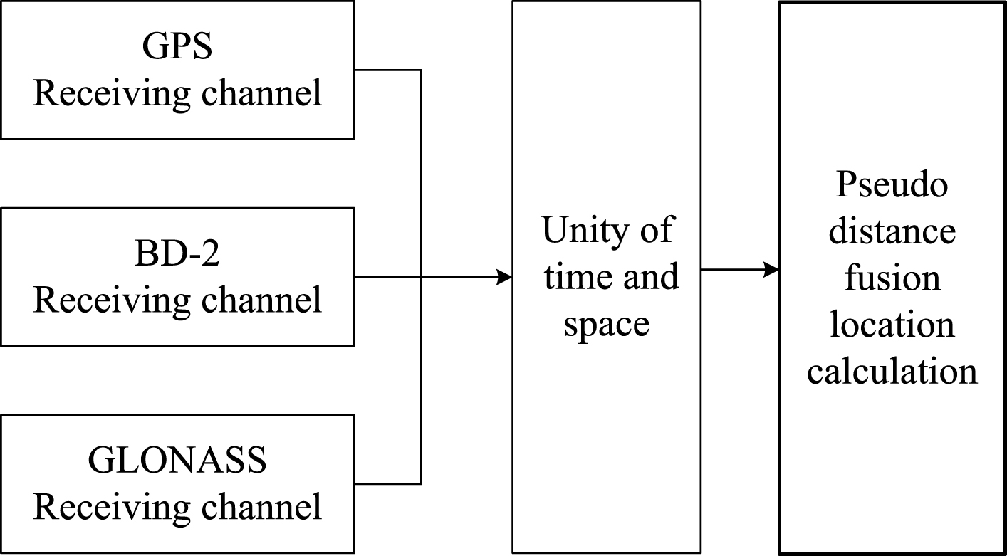
Pseudo range fusion flow chart.
The location principle of GNSS multi constellation combined location algorithm is basically the same with the positioning principle of single constellation location solution system (such as GPS system) [13]. Through the single constellation positioning algorithm, at least 4 satellite information are needed to calculate. When the two GNSS systems use multi constellation combination location solving model, the two modes of satellite system use different system time, so the unknown quantity increases the time difference between two time system and at least 5 satellite information are needed for location calculation; in the same way, in three GNSS system uses multi constellation combined location solution mode, at least 6 satellites are needed to solve the location problem. More visible satellites can improve positioning accuracy. Although the method of pseudo range fusion is relatively complex, the effect of information fusion is better. It can make better use of GDOP and RAIM technology for satellite selection and integrity detection [14].
It is assumed that at some time, the multimode GNSS receiver receives a total of n visible satellites in GPS, GLONASS and BD-2 systems. By obtaining the pseudo range and navigation message of all the visible satellites from each receiving channel, the simultaneous formulas are obtained:
Among them, ρ i represents the pseudo (x i , y i , z i ) range of the satellite i, (x i , y i , z i ) represents the position of the satellite i, (x u , y u , z u ) represents the user coordinates, and b u represents the distance deviation between the user receiver and the clock difference of the GPS system, b u = ct u ; δ b and δ g represent the distance deviation caused by the clock difference between the BD-2 system and the GLONASS system, respectively. In the BD-2 system satellite; k i and l i represent that when the satellite i is GPS system satellite, it will take zero. When the satellite i belongs to the BD-2 system satellite, then k i = 1, l i = 0. When the satellite i belongs to the GL k i = 0 ONASS system satellite, then k i = 0, l i = 1.
The formula (1) is written in a matrix form:
According to the least square estimation, it is obtained that:
The result of weighted least square estimation is:
The pseudo range observations of the satellite are subject to multiple disturbances. The pseudo range of the GPS observed from the receiver with the satellite i can be described as follows:
(x, y, z) T and (x i , y i , z i ) T are the WGS-84 coordinates of the receiver and the satellite i, respectively, ΔD i is the influence of the satellite position error to the distance, Δb i is the distance error caused by the satellite clock difference, Δv i is the distance error caused by the relativistic time correction, ΔI i and Δt i are the ionosphere and troposphere delay error respectively, b u is the distance difference caused by the receiver clock difference, e i is the receiver measurement noise error. ΔD i , Δb i , Δv i , ΔI i and Δt i can be corrected through ephemeris data. In the single frequency receiver, it can be corrected mainly according to ephemeris. It can improve the ΔI i and Δt i correction in dual frequency receiver through frequency delay characteristics. Assuming that the corrected positive term is completely corrected, the pseudo range distance formula is:
The range error e
i
caused by the receiver noise mainly depends on the tracking error of the code loop, and the tracking error of the code tracking loop obeys the Gauss distribution that the mean value is 0 and the variance is
The Gauss-Newton iterative method has local convergence [15], it has high dependence on initial value, and the convergence of Gauss-Newton is very fast when the initial value is close to true value. But when the difference between initial value and true value is high, the number of iterative times increases dramatically. The direct solution location method does not need initial value and iteration, the operation amount is small but the positioning precision is low. The new algorithm of high precision positioning combines the advantages of the direct solution algorithm and the high precision of the Gauss-Newton iterative method. Based on the GNSS multi constellation positioning algorithm, the initial positioning distance is obtained, and the precise location of the multimode GNSS is realized.
Initial location of direct solution algorithm
For the pseudo range location formula group (6), we get the square of the transfer item:
Among them,
The first formula in the formula (7) is subtracted from the two term of the unknown number, thus the purpose of linearization of the formula group is reached.
Put formula (8) into matrix form:
Where:
If there is m satellites, m - 1 formulas can be obtained from the formula (9). It is obvious that the position of the receiver can be solved directly when m > 4, and there are only three formulas at m = 4, so the formula (9) is divided into two cases:
When m > 4, the formula (9) coefficient matrix B is full rank, and the location of the receiver is to solve the linear formulas with e1 perturbation. The variance of the e1 component (δi+1 - δ1) is different because of the different ranging errors of each satellite, and the linear formulas are weighted least squares, and both sides of formula (9) are multiplied by a weight matrix W1:
The weighted least squares solution is as follows:
Where:
D (·) represents the variance. From the formula (13), we can see that the weight of the first i (i = 1, 2 ⋯ m - 1) formula is the reciprocal (δi+1 - δ1) of the corresponding standard error of
Because δ i is independent of each other and b u is small relative to ρ i , so:
Then:
So:
Handle formula (16) right into the matrix (13), then the weighting matrix into formula (12) to obtain the initial value of the position of the receiver.
When m = 4, the first formula of the simultaneous (7) and formula (7) (no redundant information is not weighted at this time, so the writing formula does not consider the random error term of the formula):
First, in the formula group Bx0 = c, the b
u
is known as the known number, x
u
, y
u
and z
u
are solved, and then x
u
, y
u
and z
u
are substituted into formula (17) to solve b
u
. Finally, the form of the solution can be obtained:
Where:
In the formula (19), we can see that the time error b
u
of the receiver has two solutions, resulting in the user’s position also having two sets of solutions. It is known from the geometry knowledge that the two sets of solutions are about the plane symmetry of the three satellites. Obviously, the group near the earth is the location of the receiver on the ground, that is, the smaller group of
The first order Taylor expansion of the distance formulas of formula (6) is carried out at the x0 of formula (11) or formula (18).
Where,
The pseudo moment ρ and δρ calculated from x0 and satellite positions are calculated from the difference between observed pseudo moment and ρ. Because the distance error of each satellite is different, the variance of each component e2 of the error term e
i
of formula (20) is different (i = 1, 2 ⋯ m), and the same is solved by the weighted least squares, and the formula (20) is multiplied by the weighted matrix W2:
The weighted least squares solution is obtained as follows:
Where,
The weight of the first i (i = 1, 2… m) equation is the reciprocal
The process of obtaining the new algorithm is to use the direct solution algorithm to calculate the user’s general position x0, to carry out Taylor expansion at the distance equation group at x0, to calculate the user position correction δx by weighted least squares, and to obtain the user location x = x0 + δx.
Perfect monitoring is one of the most important technical problems in the development of GNSS receiver, and its function is to provide alarm information for users who cannot be used in navigation service time [16]. Specifically, the RAIM algorithm is used to monitor the normal positioning results of the GNSS receiver, and to find and eliminate the data of the fault satellite when it is not working properly. It is mainly divided into two steps, the first step is the error detection, if the measurement data exceeds a certain threshold, the error of the task data is stored and the obstacle stars exist; the second step is to determine and eliminate the fault satellite, if the fault star is found, it is found according to certain rules. At present, the GNSS receiver’s self-improvement monitoring is usually based on the least square residual [17]. This study analyzes and studies the receiver autonomous integrity monitoring algorithm of GNSS receiver based on the least squares residual method, and explains the problems in the application of the algorithm to the GPS/GLONASS/BD-2 multimode GNSS receiver.
The basic principle of the least squares residual method
The observation equations of the GNSS system are as follows:
y ∈ Rn+1 indicates the difference between the measured pseudo range and the estimated value; X ∈ R4+1 indicates the true position of the user receiver and the clock difference; ɛ ∈ Rn+1 represents the pseudo distance measurement error of the satellites; and G ∈ Rn+4 is a linear matrix of the direction cosine vector process from each satellite to the user receiver.
Tracking least squares algorithm, the least square solution vector X is:
Then:
With the description of the residual vector, there are:
The analysis formula (32) is available. Vector w contains satellite ranging error information, which can be used as a basis for judging whether there is a fault star.
Based on the least squares residuals of the RAIM algorithm, the operation process is described in Fig. 3.
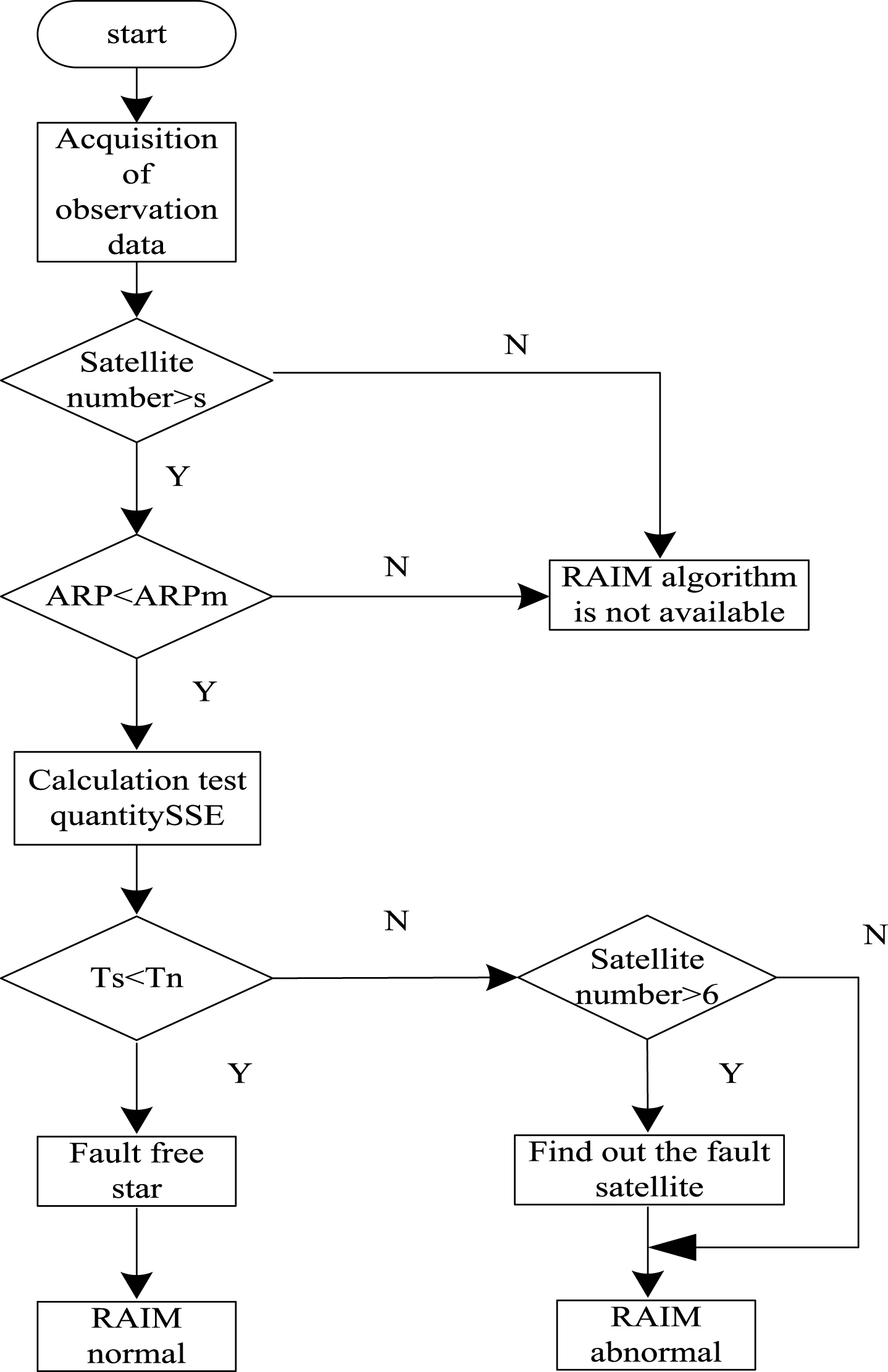
RAIM algorithm.
The description and analysis of the GNSS receiver RAIM algorithm showed that the algorithm is characterized by self-improvement monitoring through the current time data; the proposed algorithm performs error detection and error correction on the assumption that only one satellite fails at the same time. If a navigation system has more than one fault star at the same time, then RAIM can only give warning and cannot put forward the fault star. Under the single constellation positioning solution mode, 5 satellites can detect the fault star, and more than 6 satellites can be observed to put forward the fault star, and the more satellite number, the better error correction performance is [19].
The RAIM algorithm of the GPS/GLONASS/BD-2 multimode GNSS receiver is basically the same as the single constellation GNSS system, but due to the equivalent distance error of the GLONASS satellite and the slight difference between the GPS system, in the operation detection threshold, it should take the system of equivalent distance error to carry out the operation [20], which can reduce the false alarm probability of the system. At this time, there are 6 unknowns (X, Y, Z, Δt1, Δt2, Δt3) that 6 satellites are needed to locate. In this way, the degree of freedom of the system is changed from n-4 to n-6 under a single system. Therefore, in the RAIM algorithm of GPS/GLONASS/BD-2 combination location, it needs 7 satellites to detect, and 8 satellites to correct errors.
Comparison of three GNSS location algorithms
The Gauss-Newton iterative method needs to be iterated many times and each iteration also revise the position of the satellite in addition to the update of the receiver position. The tropospheric ionosphere delay also needs to be reestimated according to the latest pitching angle. It involves a large number of matrix multiplications, matrix inversion and the calculation of the mathematical formula. The number of iterations has great influence on the computation of Gauss-Newton iteration. The Gauss-Newton iteration location algorithm, the two step location algorithm and the computation amount of the proposed algorithm are statistically analyzed. The results are described in Table 1. m is the number of satellites, and k is the number of iterations.
Computational complexity of three GNSS positioning algorithms
Computational complexity of three GNSS positioning algorithms
In the simulation experiment, the initial value of the Gauss-Newton iterative algorithm uses the method of literature [7]: the initial value is set as (0, 0, 0, 0), the location of the user is 40 degrees, the longitude is 120 degrees, the height is 100 meters, the satellite is set up of 7, and the GDOP is 2.109. Table 2 gives the positioning error of the three location algorithms, and the number of trigonometric functions represents the number of times for all kinds of trigonometric and inverse trigonometry. From Table 2, we can see that the computation amount of the algorithm is about 1/20 of the Gauss-Newton iterative algorithm. The two step localization algorithm is about 1/3 of the Gauss-Newton iterative method. It can be seen that the computation of this algorithm is greatly reduced and the location efficiency is high.
Computational complexity of three GNSS positioning algorithms
Computational complexity of three GNSS positioning algorithms
The Gauss-Newton iterative algorithm, the two step location algorithm and the proposed algorithm are used to locate the data above 10 000 times. The statistical results of positioning accuracy are shown in Table 3. From the statistical data of Table 3, the positioning accuracy of the two step positioning algorithm is about 15 m, the positioning precision of Gauss-Newton is 2.44 m, and the positioning accuracy of the two step positioning algorithm is nearly 7 times worse than the Gauss-Newton iterative method. The location accuracy of the proposed algorithm is 1.65 m, which is higher than the other two algorithms, which indicates that the proposed algorithm has high location accuracy.
Positioning precision of three positioning algorithms
In this study, the accuracy of the algorithm for a high dynamic GNSS receiver is tested, and the stability and accuracy of the algorithm are verified. The detailed results are as follows:
Evaluation of level classification accuracy
According to the fitting coefficient of the horizontal component and the horizontal coordinates of each ten meter pile through each ten meter pile, the horizontal component precision in the high dynamic environment can be compared with the known horizontal coordinates, as shown in Fig. 4.
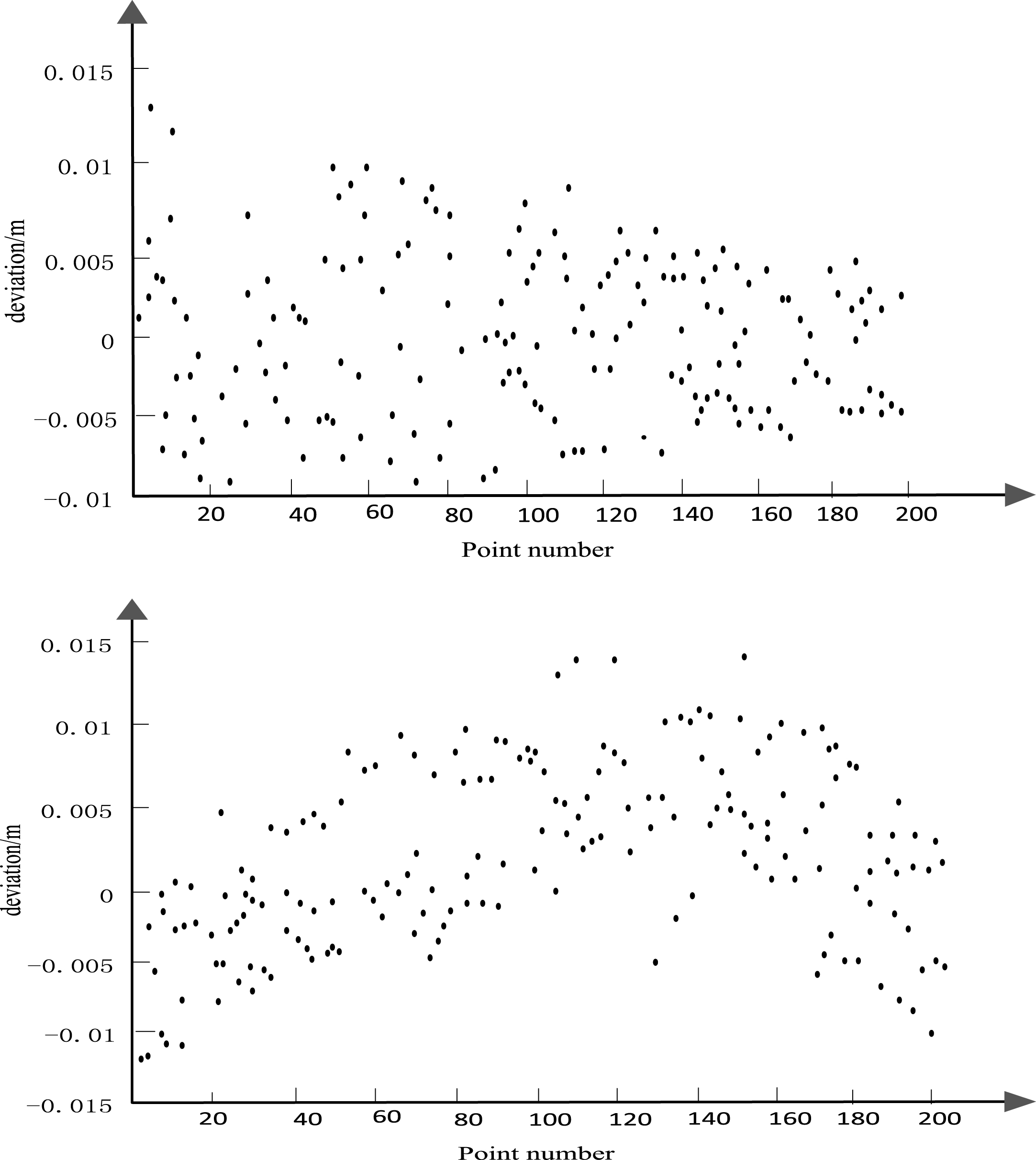
Schematic diagram of the deviation between the fitting values of X and Y components and the known values.
Most of the deviations of horizontal components X and Y are within 1 cm. The RMS of X components is 4 mm, the RMS of Y components is 5 mm, and the RMS of horizontal components is 7 mm.
The experiment selects the average value of the height observation value of the last two epochs of each ten meter pile, and compares the accuracy of the GNSS horizontal component in the high dynamic environment by comparing with the known elevation value.
As shown in Fig. 5, the result of the proposed algorithm to locate GNSS in high dynamic environment is that the deviation of the H component is within 5 cm and RMS is 2.9 cm, the accuracy of the proposed algorithm for high dynamic GNSS positioning is higher, and the higher stability of the proposed algorithm is also explained in the other aspect.

Schematic of the deviation between the fitting value of H component and the known values.
The final solution results of this experiment (Fig. 5) are compared with the results of the mature commercial software GrafNav. The concrete method is that the time system of the whole test is first unified into GPS time, then the data of this test is calculated by GrafNav, and the results of the experiment are analyzed in two ways:
Comparison and analysis of the results of location calculation with the algorithm in this paper, the contrast result is shown in Fig. 6. The analysis of the standard error (standsrd deviation, SD) of GrafNav software and the “true value difference” (the difference between the results of the proposed algorithm and the true value) were analyzed.
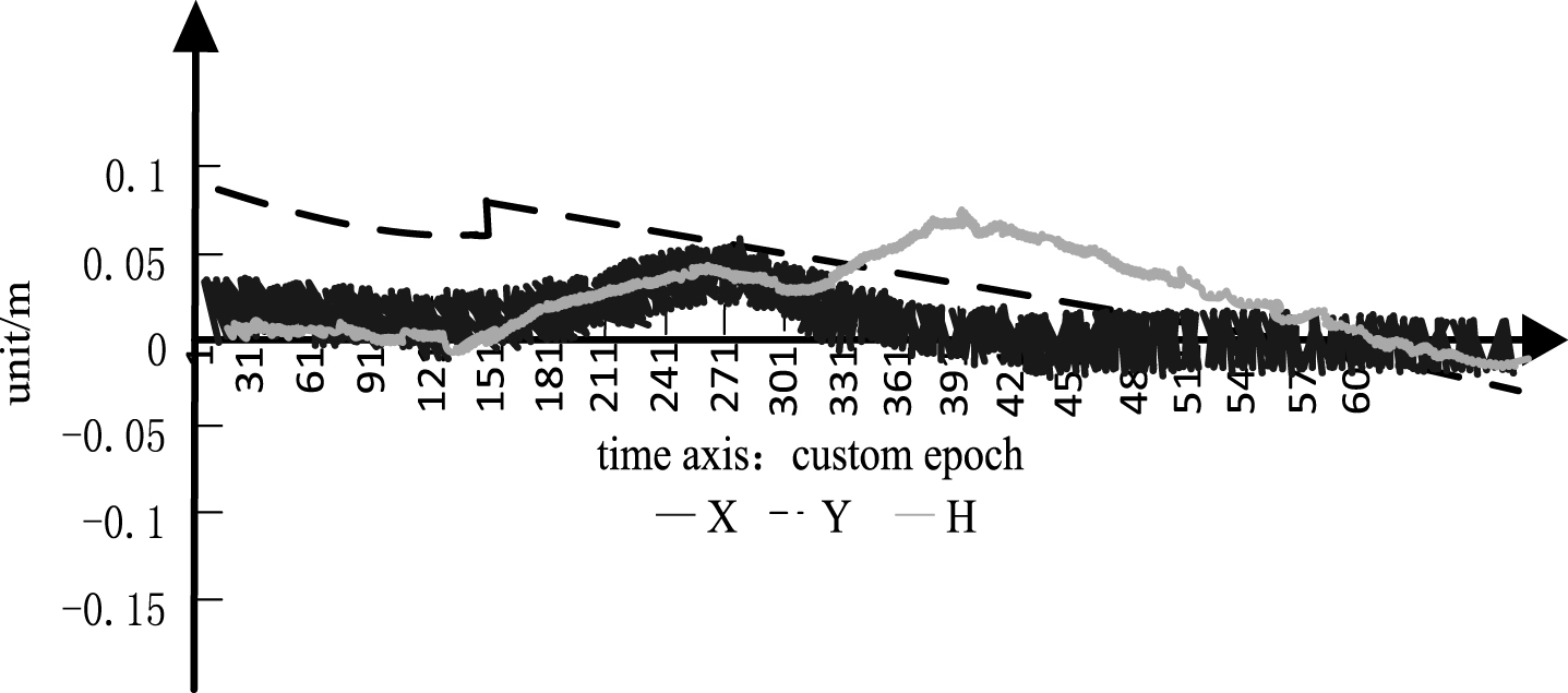
CrafNav software solution value and self research software.
As shown in Fig. 6, the results showed that the results of the commercial software CrafNav calculation are in centimeter level and the difference between the estimation error and the actual calculation error is within the centimeter level, the difference between X direction and Y direction is within 3 cm, and the H direction is basically within 5 cm, only a few epochs have gross error. Through comparison, we can see that the high precision and multi-mode GNSS localization algorithm proposed in this paper has high positioning accuracy.
In this study, a high precision multi-mode GNSS location algorithm is proposed, which solves the drawbacks of the traditional Gauss Newton iterative algorithm for the high dependence of the initial value and the independent monitoring of the GNSS in the GNSS receiver positioning process, and improves the positioning accuracy of the multimode GNSS receiver. The proposed algorithm obtains the pseudo range location distance through the GNSS multi constellation positioning algorithm, and obtains the accurate location of the user through the new algorithm based on the distance. It adopts the GNSS receiver autonomous integrity monitoring (RAIM) algorithm based on the least square residual method to realize the autonomous and perfect monitoring of GNSS, which greatly enhances the positioning accuracy of the multimode GNSS receiver.