
Abstract
The small fillet aluminum alloy cavity is a typical structure. The analysis and experiment have been conducted on the chatter at the corner of the aluminum alloy during milling process, the results show that continuity changing of spindle speed acceleration and size effect (special ploughing effect) are the main factors of chatter. The Axial Depth of Cut–Spindle Speed Analysis Method is not effective to reflect the chatter, the previous experiments have proved this point. This study investigated the cutting chatter at the corner during the circular milling process by using a new polar coordinates geometric model. The mechanics of the process are modeled by considering size effect, while regarding the ploughing effect as a new important factor. The chatter of circular milling is verified and tested both at the reduced speed of spindle and reduced feed per teeth. Acceleration of spindle speed can cause chatter and ploughing effect for enhanced chatter stability because the changed process damping occured at small size.
Introduction
Circular milling is a traditional processing method to remove excess material from the mold cavity, which belong to aeronautical parts, rocket motor case and die parts. This paper discussed the situation that the tool cutter radius are close to the corner radius of circular milling, and the situation is called as small corner circular milling in this article. Most aeronautical parts have numerous cavities to reduce the total weight of the aircraft. If the small corner circular milling is widely used to process the parts, more efficient and less process time can be realized easily.
Milling cutter cross the corner of workpiece with a small circular tool path on two dimensional plane, while there is large acceleration at the corner. As Fig. 1 shows, if the X direction speed of machine tool’s driving system can’t be reduced to zero with enough acceleration when the tool cutter arrives at the B side, the milling cutter couldn’t pass the circular tool path. However, the normal acceleration of most machine tools’ feeding system is lower than 0.5 G. There are two ways to solve the problem: one is to apply the low feed or low speed, another is to use Small Diameter Tools.

Tool Positions During Process.
In fact, using Small Diameter Tools may cause the problem of low efficiency in machining process, and the Small Diameter Tools may bear the serious tool wear at the same material removal rate. When milling cutter pass the circular corner at lower feed speed, the speed of spindle and the feed rate of per teeth should be reduced.
As the cutter travels around the circular path with a lower feed rate, intersection of the tool and the workpiece changes continuously, which leads to thin chip thickness and variation of spindle speed. The size effect and the spindle speed change of the process makes circular milling mechanics and dynamics different from the traditional milling processes presented in other literatures. And the change of spindle speed can cause different chatter mechanisms in the process, however the details are rarely concerned in high speed cutting by most scholars.
The mechanics of milling have been studied by many scholars in the last century [1, 2]. N. Kardes and Y. Altintas established a chatter stability model which can be used in the planning of chatter free circular milling operations in the industry. The Axial Depth of Cut–Spindle Speed Analysis Method is used to reflect the chatter in N. Kardes and Y. Altintas’s paper [3]. Damping are used to restrain the effects of dynamics of chatter, and ploughing effect can enhance the damping. The phenomenon has been researched by the study of Budak E and Tunc L T [4]. Suhas S. Joshi and Shreyes N. Melkote has discussed the size effect with the strain gradient, while PDZ method is regarded as a main way to explain the deformation of size effect in their paper [5]. The model developed by LI Xiaozhou and YU Huadong [6] is about Geometrically and mechanical, which can be applied to explain the ploughing and surface fracture shedding. S. Venkatachalam presented a model of friction coefficient, a series of studies of ploughing effect have been carried out to explain the damping in cutting process [7].
S. Venkatachalam noticed that there was a linear relationship between the cutting force and the cutting area, using a model of layer of cutting edge and cutting thickness, the milling chatter problem was changed into a mathematical model of intrusion problems [8, 9]. The contact length of each cutting edge and the change of the cutting area on the cutting edge will affect the cutting force and the chatter seriously.
Yusoff AR, Taloy MS, Sim. ND and Tunc LT, Budak E. proved that process damping is mainly derived from scale effect of the interference between the flank and the processing surface [10–13]. However, the relationship between the scale effect and the change of cutting parameters isn’t given an explained.
At the traditional cutting process conditions, using appropriated cutting parameters is a way to decrease cutting chatter. However, there isn’t any study to research the relationship between the changing cutting parameters and chatter in small corner and small depth cutting process. In this paper, the influence of the scale effect is analyzed, a new polar coordinates geometric model is developed and verified through the cutting process experiments [14–16].
Based on the experiences of the authors in previous, the paper main attempts to study the mechanics and dynamics of small circular milling. Henceforth, the paper is organized as following: The Application and Characteristics of circular milling is introduced in Section 2. Geometric Modeling and Size effect are regarded as the important factors of the Mechanics of Circular Milling. The new Geometric method is developed to analyze the intersection area of tool-workpiece. And a new viewpoint, which has abvious difference comparing with the study of Suhas S. Joshi and Shreyes N. Melkote, is presented to analyze size effect of cutting process. The details of the study are given in Section 3, The predictions are compared with the experiment results, and the paper is concluded with the summary of contributions at last.
The paper focus on the cutting mechanism of small corner when the feed of per teeth reduces 70% in circular milling. There is a problem that small cutting depth can cause serious size effect. To illustrate the issue that the average radial cutting depth is given by Equation 1:
Where a cav is the average cutting depth, f z is feed per teeth, D is the tool radius. The calculation results are given as following:
By the results of Equation 1, the average cutting depth is only twice of cutting edge radius (cutting edge radius is near 0.003 mm). The scale of cutting edge radius size is close to the average radial cutting depth. To account the average radial cutting depth is reduced by low speed in tool cross corner, it’s manifest that the size of average cutting depth is lower than cutting edge radius in circular milling as the result of Equation 1 show (
The result shows that the size effect appears during milling process with a small cutting depth. The corner cutting should consider the size effect as an important factor. However, the cutting size of tool and workpiece intersection has influence on size effect, which can be controlled by the geometry of tool point path. The Geometric Modeling of Tool and Workpiece Intersection and the prediction of vibration cutting forces with size effect are presented in this section.
The tool path of milling process is cycloids mode, the geometric modeling is analyzed in polar coordinates. It can get a much better result, the attempts to employ the capability of cycloids for geometric analysis purposes are better than the other Simplified Tool Path.
The f z is feed of per teeth, R is tool radius and ρ is the distance between the first tip point and the second point, the second point is the position of first tip point after one feed per teeth. Based on the relationship of f z , R and ρ, the triangle positional relationship is showed as Fig. 2.
The Position of Tool Track in Point.
And the trigonometric as follow:
If ρ was regarded as the radius of polar coordinates and the surface of ρ was regarded as projection plane, while the projection plane and the tool axis perpendicular. An approximate cycloid integral projection can be taken. By considering the helix angle of tool, the increment of per tool teeth is Δθ • ρ/cos λ (λ is the helix angle of tool). The whole path of tip point can be given as;
and is the angle of tool rotation with a feed forward, which starting at the position of initiation cutting process. θ1 and θ2, as Fig. 3 show:
The position of θ1 and θ2.
The tool forward with a feed were ready for machining, this area could be calculated as following:
While the tool begins to enter into the corner of Circular Milling, the θ1 will be enlarged by circular as shown in Fig. 4. However, once tool enter into the corner of Circular Milling, by the principle of central symmetry, the Whole Round Corner Machining has same geometric parameters which appeared in Equation 3.
Corner of Circular Milling in initial position.
In Fig. 5,

Central symmetry in corner by different position.
Traditional cutting force mainly focuses on two sections, one is shear flow stress, which stems from elastic deformation and plastic deformation of tool and workpieces at the primary shear zone, the other is the ploughing between tool flank and machined surface. In comparison with traditional cutting, small circular Milling has two ways to pass the small circular corner: the cutting depth is especially thin, when lower feed of per teeth in circular to pass the small circular. Another way to pass the small circular is lower spindle speed without reducing feed, but the chatter maybe caused by spindle speed change.
Size effect on radius cutting depth
Chip curling is frequent in milling process, chip deformation although changed form lower deformation to serious deformation. A conclusion can be drawn that the size effect constitutes an important factor in cutting, when the average radial cutting depth and federate of per teeth are small enough to near the cutting edge radius. By using Equation 3, the real cutting depth area in difference feed can be taken as shown in Fig. 6, the tool’s diameter is 5 mm, and the feed rate is respectively 0.05 mm, 0.08 mm and 0.10 mm, while speed of spindle is reduced to 30% in corner of circular milling.

The Real Cutting Depth Area in Difference Feed.
It’s manifest that lower size feed has more percent of size effect area as show in Fig. 6. The size effect area is increased by reducing the feed of per teeth. Figure 7 shows that the shear zone has a arc-shaped deformation in front of cutting edge, the plastic strain gradient η p was Stored in the shear zone, and chip. The chip deformation rate has influenced on the η p , the paper will accept the hypothesis that the dislocation mainly occur in two areas, shear zone is related to the chip deformation and the rake surface of ploughing region before the machined surface.
The shear zone related to the chip deformation can be regarded as that numerous edge dislocation surround the internal structure of chip. It is a new method compared with professor Metlke’s method that the chip can reflect more conditions of cutting process than the former scholars’ theories, such as different materials, chip deformation and the gradient of deformation. However, there are disadvantages in the method, only study one type of dislocation and need more parameters than Metlke’s method (η p = 1/L strain gradient is the reciprocal of shear zone’s length, only one key parameter.)
Chip Deformation.
From Fig. 3, the accounting equations of chip curling radius can be taken as following:
Where w is chip length, σ is the angle between chip flow and rake face, and k m is experimental coefficient (k m ≈ 2).
Where l
f
is tool-chip contact length, l
f
is given by
Where h
D
is the average chip thickness,
Setting c
x
as comprehensive material effect coefficient, the chip deformation rate ρ
x
can be expressed as following:
ρ
x
is regarded as strain gradient η
p
, while the edge dislocation is regarded as the main dislocation in cutting process.
Shear stress should be calculated using the strain gradient theory which is taken into accounting the scale effect in micro-cutting process. According to Taylor dislocation theory [8, 9], Shear stress can be expressed as following
Where α is the coefficient of empirical formula, μ is shear modulus, b is burgers vector, ρ is dislocation density to the total density of elements ρ S and ρ G , ρ S and ρ G are statistical storage dislocation (SSD) and geometric necessity dislocation (GND).
ρ
S
occurred in the process of uniform plastic deformation, ρ
G
is a reflection of strain gradient. Nye and Ashby had pointed that ρ
G
was related to equivalent plastic strain gradient, and a empirical formula with strain gradient theory has been given
Where η
p
is strain gradient,
Average shear stress can be expressed by formula
The second deformation zone and third deformation zone has been pressed by cutting edge radius, which could subject materials to elastic-plastic deformation. The pressure of the feed direction is the product of tensile flow stress σ
flow
and deformation. By cutting edge radius effect, it is found that the dominant factor of elastic-plastic deformation are ploughing and surface pressure. According to Venkatachalam [7], the adhesive friction coefficient can be deduced to study ploughing-extrusion model.
Where δ is friction coefficient of ploughing, a parameter that describes the ratio of cutting edge radius and feed per teeth.
To regard the material extending on rake surface as the important factors of deformation, the value of slip strain can be calculated by formula as following
Where ɛ is slip strain, φ1 is shear angle, γ is rake angle, ξ is the ratio of chip thickness and average radius cutting depth.
Thus, the real cutting depth t1 has been regarded as the difference between u and theoretical cutting depth a
c
. As the Fig. 8 shown, the expression of the real cutting depth t1 = a
c
- u was derived from the effect of cutting edge radius. The formula u = r
e
- r
e
sin(β - γ0) can elaborate the relationship between the cutting edge radius r
e
and u [6]. Thus, the ploughing effect cutting force can be expressed as following by integrated Equations 11, 12 and 13.

Chip deformation in cut ting process.
In previous parts, the model of circular milling with small corner has been introduced and size effect approaches has explained in detail. In order to verify the chatter and size effect for circular milling, a series of experiments were conducted for a range of axial depth of cut and spindle speed value.
The tool, workpiece, machine tool and measuring instrument are given as follow:
Cutter tool having 30° helical angle, φ = 16 mm and N = 2 teeth was used. AL7075 was used as the workpiece. The type of Cutter tool is M.Ford13562992. Machine tool is the MICRON UCP710 five-axis machining centers, Spindle speed 18000 r/min. measurement instruments.
The cutting force was collected by Kistler 9265B piezoelectric dynamometer, 50l9Acharge amplifier; BSWA sound transducer-type MP201.
Change the spindle speed
Axial Depth of Cut-Spindle Speed Analysis Method was used to analyze the chatter of circular milling by NIMET KARDES. As Fig. 9 shown, NIMET KARDES regarded the Axial Depth of Cut and the Spindle Speed as the Main Factors, the chatter should be identical in the same Axial Depth of Cut and Spindle Speed in the analysis chart.

Axial Depth of Cut–Spindle Speed Analysis Method by Nimet Kardes.
The 5-axis corner of an aluminium aeronautical pocket has been machined with a flat end millφ16 mm and a programmed spindle speed of 11000 n/r. However, the results show the difference in the process with same spindle speed. As Fig. 10 shown, A and B has same spindle speed in most area, but only B appears serious chatter, while the experiment parameter is n = 11000 rpm, and a p = 8 mm, a e = 0.25 mm, f = 0.05 mm. C region is the beginning of cutting process.
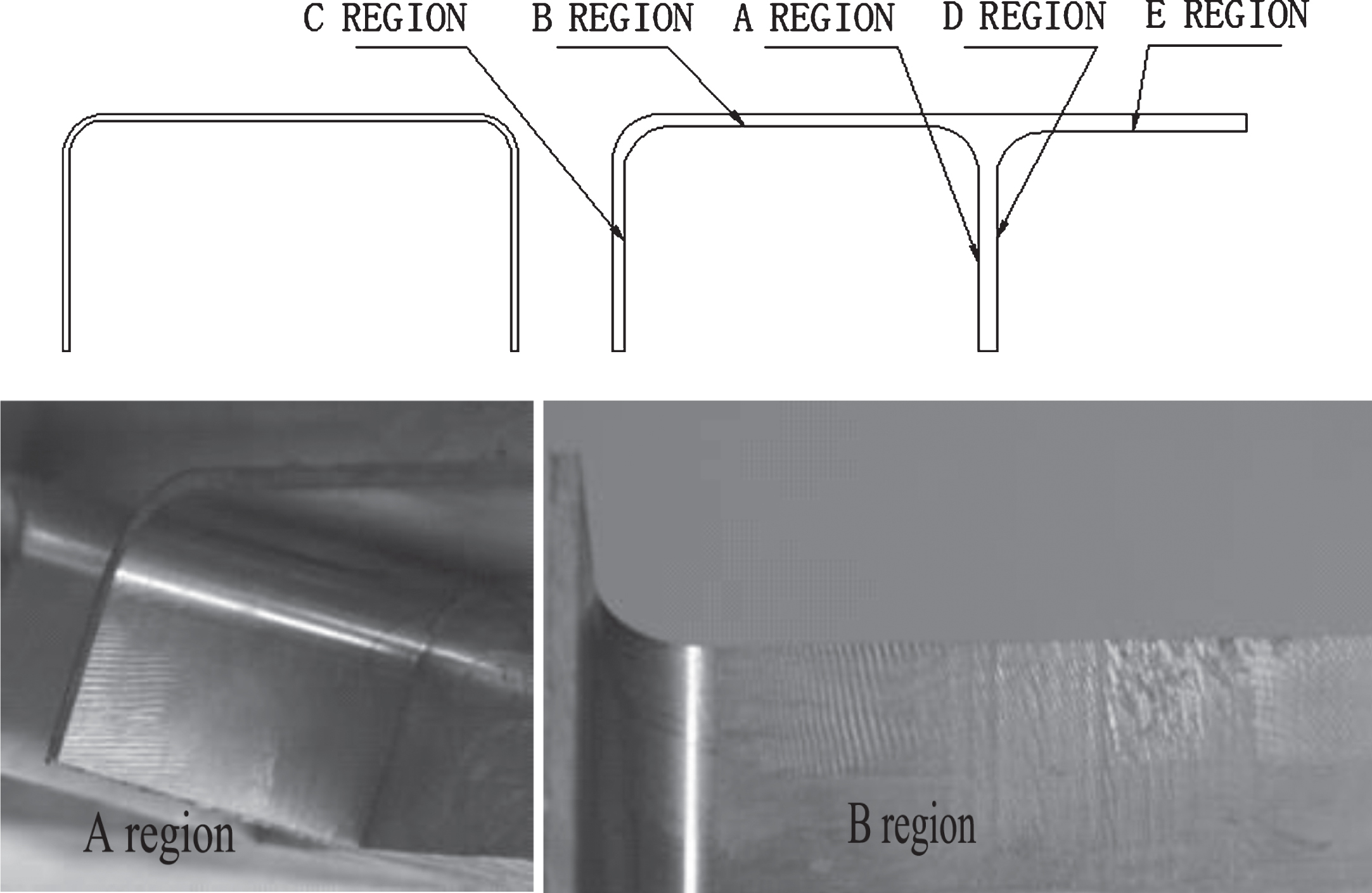
A-E Cutting Region and A-B Chatter Waves in Workpiece.
Axial Depth of Cut–Spindle Speed Analysis Method is unsuitable for circular milling, while the Spindle Speed is changed greatly in small circular milling. The acceleration is a key factor in circular milling. There isn’t any chatter in the C, to compare B side and A side, which cause the very large fluent of cutting force.
The similarity of experiment has occurred in the A-C, as Fig. 12 shown, there are same parameters with out axils depth of cut. The only difference between Figs. 11 and 12 is the degree of chatter, because of the different axils radius cutting depth.
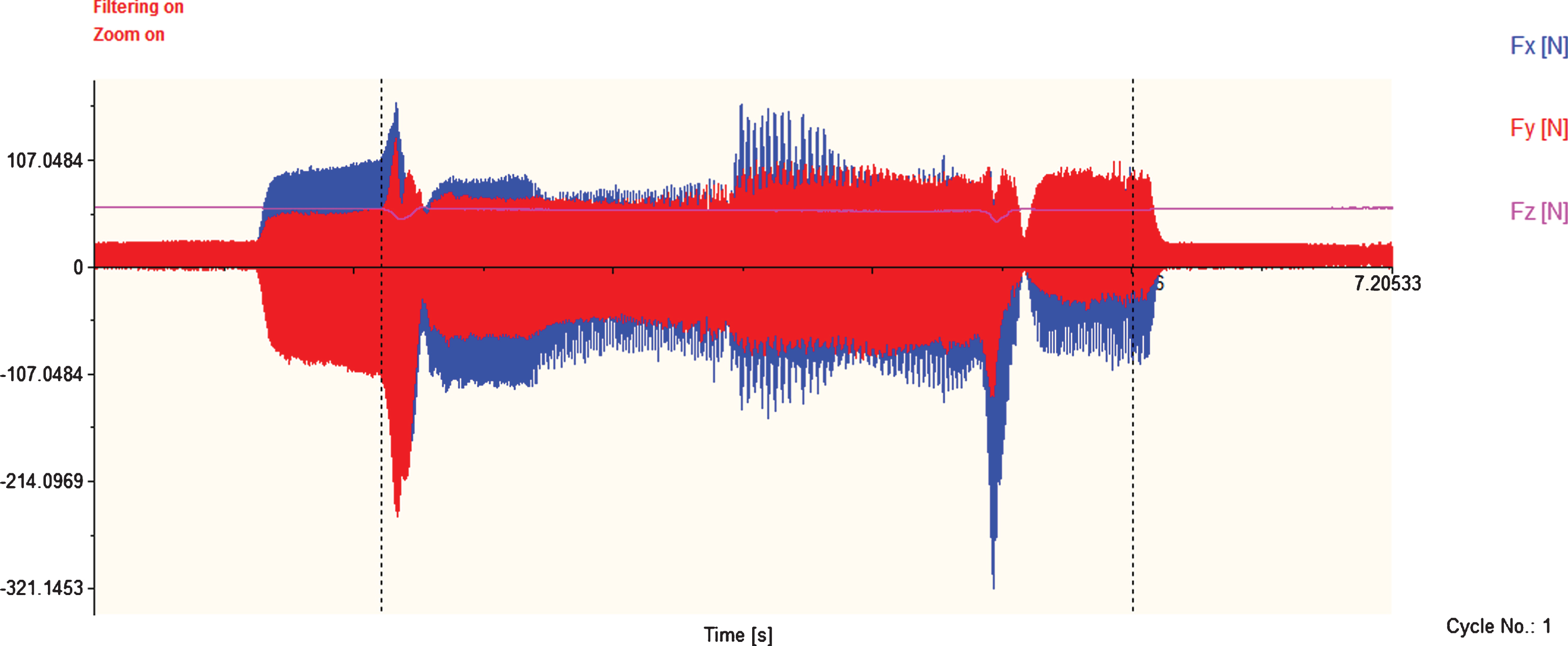
Axils Depth of Cutting is 8 mm in A-C side.
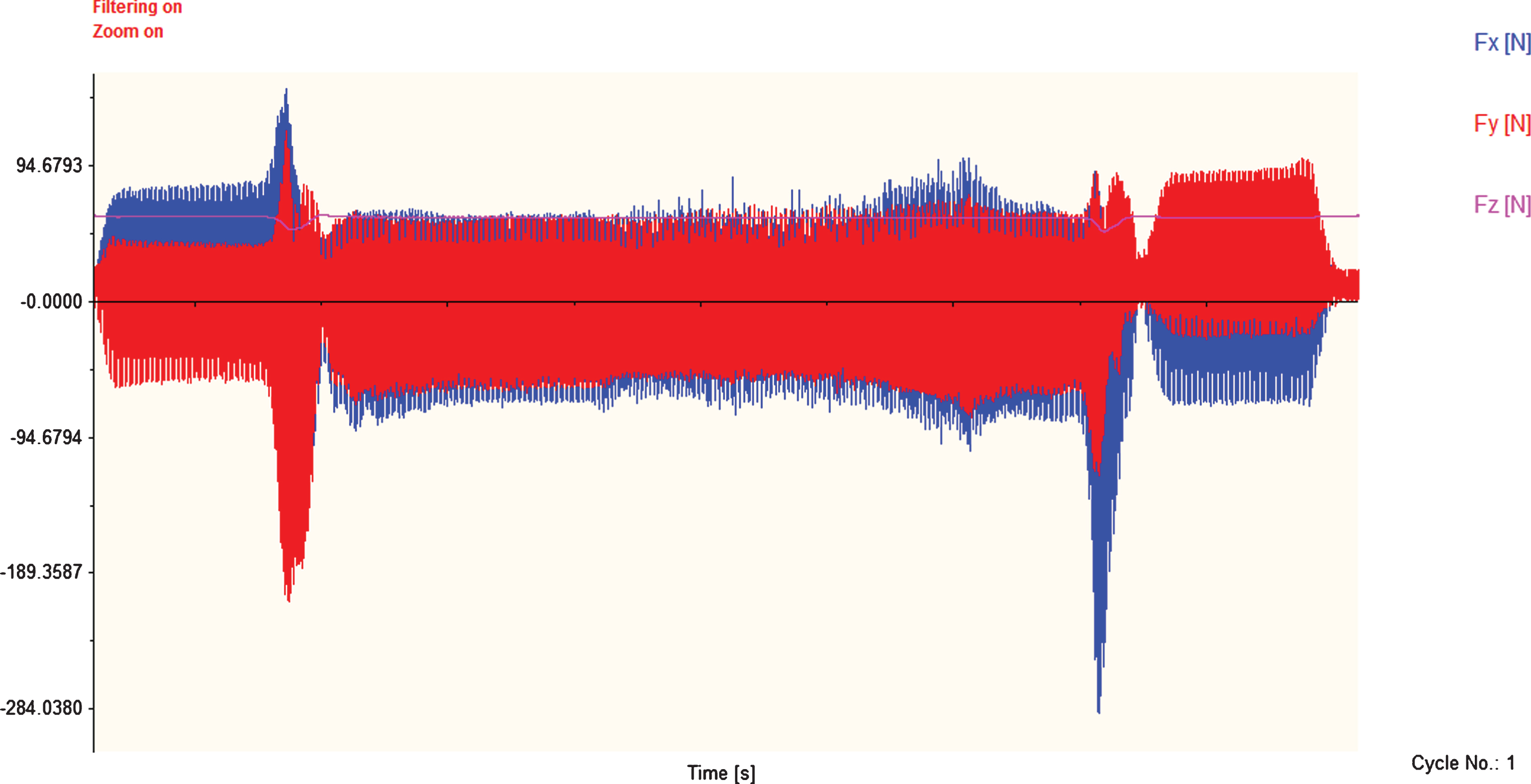
Axils Depth of Cutting is 7 mm in A-C side.
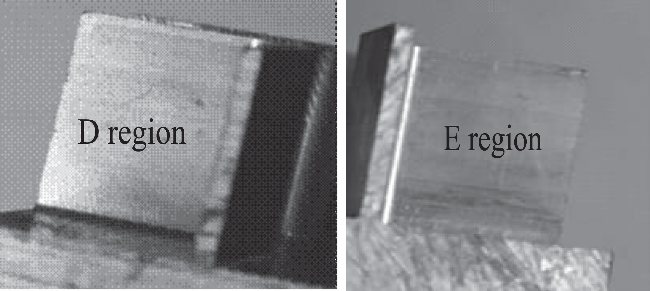
D-E Chatter Waves in Workpiece.
Although, the chatter doesn’t appear obviously in all the experiments due to the axial cutting depthes are smaller than 7 mm, but there will be different chatter degree at different reduced speeds. As Figs. 10 and 12 shown, D-E side has same cutting parameters as A-C beside the acceleration (D-E reduce 60% speed of spindle in the corner of circle milling, while A-C reduce 70% speed of spindle), but D-E has a smooth surface without any vibration waviness.
According to Hoshitetsu Taro£¬the Stiffness has been regarded as a constantly changing parameter in chatter or MRE. And Stiffness K
c
is showed as following
In the paper, K c is dynamic stiffness coefficient, F y (t) is cutting force with Equation 14, A c (t) is invade area of milling with Equation 4.
It can be easily proved that the small size cutting depth will change normal force greatly according to the results of many studies [5], as size effect has influence on mesoscale turning Processing. Therefore, k c would be changed largely by changing cutting force in small radial cutting depth. In the different cutting parameters, the chatter appears different situation. By using Equation 15, a group date of kc1 = F E /A c (t) coefficient is given to compare the experiments Kc2 = F y (t)/A c (t), as Table 1 shown. F E is cutting force which was collected in experiments.
Cutting conditions used in simulations and experiments
Tool cutter with 30 deg helix, Workpiece = Al7075, N = 2teeth, (Abbreviations: S: cutting signal stable, U: unstable but surface smooth, UC: cutting signal unstable with serious wave of chatter).
According to the experiments, chatter appears when k c is near 300 in cutting process, however the cutting process is stability in k c more than 500. It’s clear that dynamic stiffness k c can be regarded as an independent parameter to reflect the chatter.
The correlation coefficients between kc1 and kc2 is 0.7686, its’ mean two group database has an ideal Correlation Structure, to compare 0.8 correlation coefficients which is called high correlation degree. It could be useful that kc1 and kc2 have a high Correlation Structure. Once the anyone kc2 can be gotten by experiment, the degree of chatter can be evaluated easily (kc1 would get by using Equation 15). The kc1 can be used to FEM for an index for evaluating the degree of chatter.
According to the feed rate of per teeth and speed of spindle, the whole cutting process, which located in corner of circular milling, has forty eight tooth profile signals. The cutting force is affected by the reduced feed per tooth, and the result of cutting force has too many signals’ burrs to ignore. As Fig. 14 shown, when the cutting process star reduce the feed of per teeth in corner of circular milling, the signals’ burrs is serious unless the deceleration closed to end.

experiment results for circular milling, n = 11000 rpm, and a p = 6 mm, a e = 2.75 mm, f = 0.05 mm.
To discuss the size effect in small circular milling, a group of experiments of cutting process has been conducted. Cutting parameter as following: axis cutting depth is 6 mm, speed of spindle is 11000 n/r, feed per teeth is 0.05 mm and the feed per teeth is reduced to 30% in corner of circular milling (It means the feed of per teeth only 0.015 in the corner of circular milling). Three experiments have the same parameters except radius cutting depth, as Fig. 15 show. However, comparing a), b) and c) in Fig. 15, there are great differences among three experiments. The signal’s burr appeared widely and seriously in feed reduced area and corner process of circular milling while radial cutting depth is 3.5 mm, but disappeared in radial cutting depth is 0.25 mm. The appearance of signal’s burr often means chatter.

experiment results for circular milling, n = 11000 rpm, and a p = 6 mm, f = 0.05 mm, while in different radial cutting depth.
The paper has discussed that the relation between the size effect and radial cutting depth in previous. According to Equation 1, when the radial cutting depth is 0.25 mm and the feed per teeth is 0.05 mm, the average cutting depth is lower than cutting edge radius of tool. The high plough effect would be caused by size effect while increasing damping in Tool- Workpiece System, therefore the Cutting Chatter is decreased by high deceleration of corner in circular milling.
As Fig. 16 shown, by analyzing the sound signal of 3.5 mm radial cutting depth, there has a high chatter frequency which can reach 3844 Hz.

Spectrum of Chatter by Sound Signals in high frequency.
The sound signal of 2 mm radial cutting depth only has 366 Hz, as shown in Fig. 17, which means the chatter can be ignored when radial cutting depth lower than 2 mm. The other sound signal of mm radial cutting depth doesn’t appear so high chatter frequency. It means that the serious chatter only appear in big radial cutting depth while 7 mm axis cutting depth and 11000 n/r spindle speed are applied in corner of circular milling.
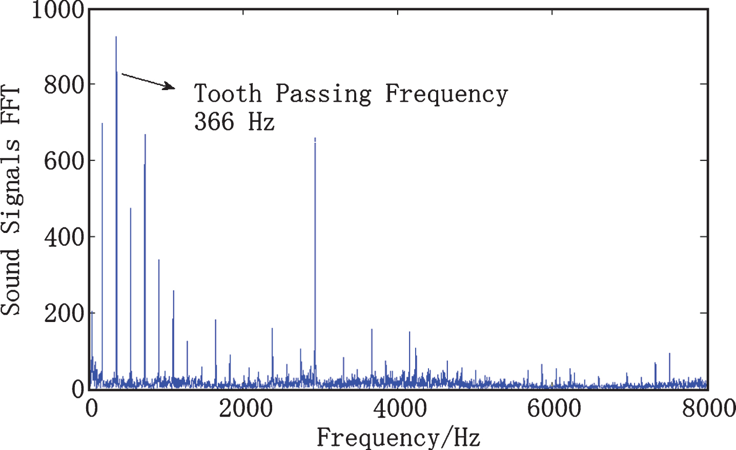
Spectrum of Chatter by Sound Signals in low frequency.
The vibration signal and spectrum analysis show that the trend of vibration frequency has been synchronous with the cutting force change. Furthermore, it’s different from line cutting process and Circular cutting process on the synchronization. This conclusion is confirmed by the traditional method of leaf disc analysis.
The axis cutting depth and speed of spindle are main factors about chatter in cutting process, but the acceleration and size effect (special ploughing effect) are other important factors. The Axial Depth of Cut–Spindle Speed Analysis Method is not effective to reflect the chatter, though the previous experiments have proved this point.
The geometric and the dynamics model of circular milling process are discussed in this paper. The small cutting depth and change speed of spindle have different influence on the process of circular milling, hence, the way to pass corner of circular milling is an important issue.
The study shows that: To decrease the speed of spindle, the chatter occurs at the high acceleration, even wave of chatter appears at the end of corner when a big axis cutting depth and lower radial cutting depth are applied on cutting process. To decrease the feed of per teeth, the chatter occurs with a high frequency which reached to 3844 Hz in the corner of circular milling.
The results give a guide of the manufacture of aeronautical parts, which have multiple opening cavities.
By reducing the speed of spindle to pass the corner of circular milling, it can’t be applied on small radial cutting depth. To rephrase the statement, the method can’t be used to finish Machining. As the experiment show, radial cutting depth should be larger than 0.25 mm at least, the best situation is not less than 1.5 mm. Ploughing effect would be caused by Size effect when the feed per teeth is decreased seriously in the corner. Damping would decrease the chatter of cutting process by Ploughing effect. Big radial cutting depth, which is more than 3.5 mm, can cause high frequency chatter. The axis cutting depth and speed of spindle are the main factors of chatter in cutting process, but the acceleration and size effect (special ploughing effect) are other important factors. The Axial Depth of Cut–Spindle Speed Analysis Method is not effective to reflect the chatter. Using the dynamic stiffness coefficient kc1, the chatter can be evaluated easily wether there is one or several cutting forces. However, this method has high value for preventing process chatter during cutting numerous cavities materials by modifying cutting parameters. But the accuracy and application in FEM are key study directions in the future.