
Abstract
At present, obstacle avoidance systems of robots cannot avoid obstacles with high efficiency, high stability and high precision. Thus, a self-adaptive obstacle avoidance fuzzy system for mobile robots based on ultrasonic range measurement is proposed and designed. An upper computer, a motor drive module, an ultrasonic ranging sensor module, an infrared sensor module, an electronic compass module, a communication module, a power supply module and peripheral circuits are connected to form the system hardware. After the system is initialized, the robot starts to work according to instructions of the upper computer and enters the self-adaptive obstacle avoidance subroutine. In the subroutine, the ultrasonic sensor scans the infrared sensor output at the corresponding position. After receiving reflection information of the ultrasonic wave, the counter is stopped, and reflection time of the ultrasonic wave is simply calculated and cached into the buffer, so as to determine whether there is an obstacle in front, and the result is fed back to the upper computer through the RS485 bus. If there is an obstacle, then the interrupt program will be called, and the electronic compass program is utilized to determine the direction to avoid the obstacle; if there is no obstacle, the robot will continue to move following instructions of the upper computer to complete the system software design. Experiments show that the average time to avoid obstacles using this system is 0.40 s, and the obstacle avoidance accuracy is high and the stability is good. Under the data comparison and analysis, the proposed system is obviously superior to current systems in the time-consuming and accuracy of obstacle avoidance, and has great reliability.
Introduction
Robotics is a new discipline that has rapidly developed in the new technology revolution. It has been widely used in many fields of science and technology and production, and has shown great vitality. It is a comprehensive new technology discipline that integrates precision machinery, optics, electronics, inspection, automatic control, computer and artificial intelligence technologies [1]. Although machine vision technology still faces some problems that need to be solved, with the in-depth research of machine vision technology and the continuous improvement of intelligent and computer technologies in the recent years, the robot will soon complete tasks successfully in an unknown and complex environment in the future. Thus, the current research on positioning and obstacle avoidance system of mobile robots is very necessary. With the continuous deepening of research, there have been many related results. Several excellent achievements are listed below.
An optical flow-based obstacle avoidance method for mobile robots was reported [2]. The assumption of gradient conservation and local weighting are introduced to improve the optical flow algorithm, which reduces the impact of uneven illumination and noises on the optical flow algorithm and improves the accuracy and robustness of the algorithm. And the optical divergence is utilized to calculate the collision time and TTC is adopted to construct obstacle maps. The designed heading decision algorithm can select the optimal direction for the robot when the robot and the obstacle collide. The proposed obstacle avoidance method is simulated and the physical experiment is conducted. The experimental results show that the mobile robot can achieve collision-free walking in a complex and unstructured environment, but the obstacle avoidance efficiency is low. Also, a robot obstacle avoidance method based on the improved artificial potential field was described [3]. The obstacles in the unknown environment are designed in the form of a grid map, which allows the robot to avoid obstacles and move toward the target through perception. The MATLAB GUI is used to set up a two-dimensional coordinate system environment that contains obstacles and target points. In the plane map, the robot moves along the optimal trajectory from the initial position to the desired position. The test results show that this method has high obstacle avoidance efficiency, but its operation stability is poor. Other than these, a robot obstacle avoidance control system based on ARM and FPGA was came up with [4]. ARM and FPGA are employed as system hardware and the software is designed according to site requirements. The experimental results show that the designed mature fruit recognition and obstacle avoidance control system for strawberry picking robots can accurately identify the mature strawberry, and avoid the obstacles, but the obstacle avoidance takes a long time, ie, the efficiency is low. Besides, a robot obstacle avoidance method based on the survival area was brought up [5]. The survival area method is combined with the robot model to transform obstacle constraints into a set of survival inequalities. In order to ensure that the robot can avoid obstacles in the vicinity, a sufficient proof of the overall survival of the area is given. At the same time, in order to meet the basic navigation requirements, the directional controller required for this requirement is designed. Finally, the survival inequality and directional controller output will be used as a set of constraints to convert the wheeled robot obstacle avoidance into a set of linear planning problems. The robot can optimize specific indicators based on navigation needs, such as maximizing the control output to achieve aggressive high-speed obstacle avoidance. In addition, the effectiveness of the survival controller is verified by simulation results of different controller parameters, and the influence of control parameters on the sports performance is demonstrated. The overall operation of this method is good, but there is a problem of poor stability. Zhang el al. proposed a path fuzzy control method based on improved jump point search [6]. Jump point search is performed at the same time from the horizontal, vertical, and diagonal directions of the starting point. The binary table is used to optimize the open table to continuously search for and add jump points until the target node is obtained. The obtained path node is used as a sub-target point and combined with fuzzy control to detect and avoid obstacles for local unknown obstacles, and move to the target point to complete global path planning. The experimental results show that this method is relatively simple to operate, but it has the problem of low obstacleavoidance accuracy.
In order to solve the problems in the current research results, a self-adaptive obstacle avoidance fuzzy system based on ultrasonic range measurement is proposed and designed. The overall framework is as follows:
An upper computer, an ultrasonic ranging sensor, an infrared sensor, an electronic compass, a communication module and a power supply module, and peripheral circuits are combined to set up hardware part of the system. The system power supply module uses an isolated power supply to improve the system’s anti-interference performance [7]. Combined with ultrasonic range measurement, infrared range measurement and electronic compass modules, the obstacle avoidance accuracy and efficiency of the robot self-adaptive obstacle avoidance system can be improved.
After the system starts running, the robot runs according to the instructions and enters the self-adaptive obstacle avoidance program at the same time. This program is used to determine if there is an obstacle in front of the robot. Different subroutines are called according to different judgment results to complete the system softwaredesign.
An experimental platform is built on Simulink to verify the overall effect of the proposed system on system operation stability, obstacle avoidance efficiency, and obstacle avoidance accuracy.
The conclusion is summarized and ideas for future development are proposed.
Material and methods
Hardware design of the self-adaptive obstacle avoidance fuzzy system of mobile robots
Hardware of the self-adaptive obstacle avoidance fuzzy system of mobile robots takes ATmega128 as the core, mainly including a power module, a motor drive module, an ultrasonic range measurement sensor module, an infrared sensor module, an electronic compass module, a communication module and necessary peripheral circuits, such as a clock circuit. The overall hardware structure is shown in Fig. 1.
The upper computer in Fig. 1 forms the motion instruction after combining all kinds of sensor information through the navigation program, and sends to the motion control system through the serial port communication module. After the motion controller receives the instruction, it calls the control program, calculates and outputs the control signal of the left and right motor, detects the feedback signal and sends relevant information to the upper computer as needed.

Structure of self-adaptive obstacle avoidance fuzzy system of mobile robots.
The minimum system in the ATmega128 includes a clock circuit, a reset circuit, and a programming interface circuit. Among them, the clock circuit and reset circuit are shown in Figs. 2 and 3.
The clock generator in Fig. 2 provides clock signal to the ATmega128. The clock generator includes an internal oscillator and a phase-locked loop circuit. Clock interface mode of the ATmega128: the 20 MHz crystal oscillator is positioned between the clock pins X1 and X2, and two l0 pF capacitors are added to form a capacitive three-point oscillator with the ATmega128 internal oscillator, so as to provide clock source for the system.
A clock circuit of the system.
The reset circuit in Fig. 3 consists of a capacitor, resistors, and a push button switch that allows manual reset. The capacitor and resistor constitute a delay charging circuit. When the power is loaded, the power supply voltage charges the capacitor C through the RC series circuit and the charging time is t = RC. When the charging time exceeds 5t, the voltage on capacitor C approaches the supply voltage and the reset is completed. For the ATmega128, the reset time is required to exceed 6 clock cycles.
A reset circuit of the system.
The ATmega128 has three programming modes: parallel programming, SPI serial programming, and JTAG interface programming. SPI serial programming mode is selected in this system.
System power module: for mobile robots, the power supply is usually battery, which is provided to the power device and each logic device. For an electromechanical control system, the system’s anti-interference performance is very important [8]. Providing isolated power supplies for different functional components is an important means of improving anti- interference performance and enhancing system stability. The power module of the system is shown in Fig. 4.
System power module.
In the motor drive module, the selected motor type is D6015-30A, and the speed is 3000r/m, equipped with a speed reducer with a 1:30 reduction ratio. It has the characteristics of fast response, stable running speed, etc., which can improve the stability of the system [9]. The microcontroller is used to control the switching of power devices for PWM modulation. The motor drive module is L298N. L298N is a power integrated circuit with dual H-bridge, high-voltage and high-current, which can be used to drive inductive loads such as relays, coils, DC motors, and stepper motors. It is packaged in a Multiawatt plastic and contains four separate push-pull drives, which can form H-bridges, and each H-bridge has its own enable control. Each H-bridge has its own input control terminal, the control terminal signal is TTL level, and there is a power supply for logic parts inside the chip [10]. In order to increase the drive current, the output terminals OUT1 and OUT4, OUT2 and OUT3, and the input terminals IN1 and IN4, IN2 and IN3 are connected in parallel, so that a maximum driving current of 3.5 A can be obtained. The PWM output and I/O ports of the microcontroller ATmega128 are connected to the enable and input control terminal of the L298N, respectively, to control the speed and direction of theDC motor.
Ultrasonic sensors as the range measurement sensor for obstacle avoidance of robots are very important for self-adaptive obstacle avoidance of mobile robots. The superiority of the ultrasonic sensor is mainly manifested in the following points: 1. The ultrasonic sensor can still accurately detect the obstacle information in real time in a harsh environment and feed it back to the information processing equipment. 2. Compared with optical sensors, ultrasonic sensors not only can detect the presence of obstacles, but also can get the distance between the obstacle and the robot, making it easier for robots to make decisions [11, 12].
Considering comprehensively, the ultrasonic range measuring block diagram of this system is shown as in Fig. 5. There are mainly five parts: ultrasonic emission part, ultrasonic reception part, temperature detection part, CPU part and communicationpart.
In Fig. 5, the ultrasonic wave generator is used to generate 40 KHz ultrasonic wave, which is emitted through the emission transducer driven by a driving circuit. The ultrasonic receiving section is used to detect ultrasonic echo signals. The ultrasonic echo is received by the ultrasonic transducer, and the capacitor is used to filter the straight lines. After the three-level amplification, the signal enters the comparator LM393, and the signal output by the comparator enters the microcontroller to generate an interrupt for timing. The temperature detection part adopts the DS18B20 to measure the ambient temperature and uses temperature compensation to correct the ultrasonic velocity to reduce the influence of the temperature change on the range measurement accuracy and improve the obstacle avoidance accuracy and efficiency. The CPU generates control pulses to control the emission of ultrasonic waves, and processes and calculates the echo signals, and transmits results to the host through the communication section. The communication part mainly completes the data transmission between the CPU and the host of the ultrasonic range measurement system. The self-adaptive obstacle avoidance system of the robot based on the ultrasonic wave adopts the 485 bus.

Structure diagram of ultrasonic range measurement.
According to the high-precision requirements of robot obstacle avoidance system, PSD infrared sensor is used as a supplement to the ultrasonic sensor to compensate for the blind spot of the ultrasonic sensor. PSD is a new kind of semiconductor light sensor developed for the accurate measurement of position, displacement and distance. It uses the transversal photoelectric effect of the semiconductor to measure the position of the incident light spot. The main features are as follows:
Fast response. The photoelectric conversion response speed of the PSD is much higher than that of a scanning type photosensitive device such as a CCD.
The location resolution is high. Since the sensitive surface of the PSD device is continuous, its resolution is related to the noise of the external detection circuit and the photocurrent generated by the incident light [13].
The peripheral circuit is simple, the signal detection is convenient, and the cost is low.
The infrared sensor utilizes the blocking or reflection of object to be detected for the infrared light beam to detect the presence or absence of an object. The object is not limited to metals, and all objects that can reflect light can be detected. The existing photoelectric sensor preferentially uses near-infrared light with a wavelength of 780 nm to 3 um, and has relatively stable integrated products, and the interface with the digital circuit is also very simple, as shown in Fig. 6.
The output of the PSD infrared sensor in Fig. 6 is the switch quantity, and it can only be judged that there is an obstacle within the measurement distance. The sensor has a sensitivity adjustment knob which can adjust the distance of the sensor trigger. With the different supply voltage, the furthest detection distance is adjustable from 5–60 cm.
The principle of infrared sensor range measurement.
The electronic compass (digital compass, electronic compass) is an electronic instrument that measures the azimuth (heading angle) economically. Recently, electronic compasses have been widely used in high-performance navigation devices such as automobiles, marine and aviation, and mobile robots, which require sensing of orientation or attitude [14]. The principle of electronic compass is to use magnetic sensors to measure the magnetic field. The Earth’s magnetic field intensity is 0.5–0.6 Gauss, parallel to the ground plane, and will always point to the magnetic north pole. The magnetic field is roughly bipolar: the magnetic field in the northern hemisphere points downwards, and the magnetic field in the southern hemisphere points upwards. Because the horizontal component of the Earth’s magnetic field is always directed toward the magnetic north pole, the electronic compass system can be used to determine the obstacle avoidance direction.
Combination of ultrasonic range measurement, infrared range measurement and electronic compass sensing systems can greatly improve the obstacle avoidance accuracy and efficiency of self-adaptive obstacle avoidance system of robots. Three methods are merged in the proposed system. When studying the obstacle distance detection of obstacle avoidance system for mobile robots, the ultrasonic sensor is mainly used, and the infrared sensor is auxiliary. The infrared sensor is mainly used to make up for some defects of the ultrasonic sensor, and is used for emergency obstacle avoidance. As shown in Fig. 7, the ultrasonic sensors 1, 2 and the infrared sensors 1, 2 are grouped in the left direction, the ultrasonic sensors 3, 4 and the infrared sensors 3, 4 are grouped in the forward direction, and the ultrasonic sensors 5, 6 and the infrared sensors 5, 6 are grouped in the right direction. The specific fusion rule is: in each group of sensors, if an infrared sensor has detected an obstacle within its detection range (roughly 5cm–60 cm), the measured value of the infrared sensor is used as the detection value of obstacle in the direction. The measured value is used as an input for fuzzy control. If the minimum value of two ultrasonic sensors is greater than the maximum detection distance of the infrared sensor, the detection results of the infrared sensor can be ignored. At this time, the fusion value of two ultrasonic sensors is taken as an input for fuzzy control [15]. If the ultrasonic reading is at its maximum, the actual distance is greater. When these rules are applied to ultrasonic and infrared sensors, a spatial depth map can be created with greater accuracy than the individual sensor.

Ultrasound and infrared sensor structure of mobile robots.
According to the structure shown in Fig. 7, the distance between the mobile robot and the obstacle is measured by the ultrasonic and infrared sensors. At the same time, the azimuth of the robot and the obstacle is measured by an electronic compass, and then sent to the fuzzy controller for information fusion to control the movement speed of the left and right wheels, so as to control the robot turn left, turn right, or go straight. Three devices complement each other to improve efficiency of the system.
The upper computer or PC in the system is the top manager of the entire mobile robot hardware system, and it is the host of hardware system. The basic communication protocol block diagram is shown in Fig. 8.
Basic communication protocol block diagram.
Figure 8 indicates that the ultrasonic and infrared sensors and the electronic compass both communicate with the PC through the RS485 bus in the sub-device mode. All module devices connecting to the RS485 bus must convert other signals into RS485 level, and always enable the receiver. The transmitter enable terminal is connected to the controller of the device, but only enables when sending reply data. High impedance is set immediately after sending the signal.
Based on the above content, the self-adaptive obstacle avoidance fuzzy system hardware based on ultrasonic range measurement is mainly composed of an upper computer, a system power supply module, a motor drive module, an ultrasonic sensor, an infrared sensor, an electronic compass, and a basic communication protocol. Among them, the use of isolated power supplies for different functional components improves the anti-interference performance, thereby enhancing system stability. Combining ultrasonic range measurement, infrared range measurement and electronic compass to improve the obstacle avoidance accuracy and efficiency of self-adaptive obstacle avoidance system of robots.
The software design of self-adaptive obstacle avoidance system for mobile robots is mainly to control various parts of the hardware to realize the normal operation of the entire system. The most important part of the entire system is the obstacle avoidance control unit. The software design is based on this part. Among them, the main control program of system software is shown in Fig. 9.
Main program flow of system software.
In the main program of self-adaptive obstacle avoidance fuzzy system software for mobile robots, after the system is initialized, the robot runs according to the instructions, and then enters a self-adaptive obstacle avoidance program [16–19]. This program is used to determine if there is an obstacle in front of the robot. If the result of the judgment is yes, the interrupt program is called, and the obstacle avoidance direction is determined by the electronic compass, so that the robot can avoid the obstacle. If the result is no, continue to follow the instructions.
The information processing software flow chart of ultrasonic sensor and infrared sensor in the system is shown in Fig. 10.
Information processing software flow of sensors.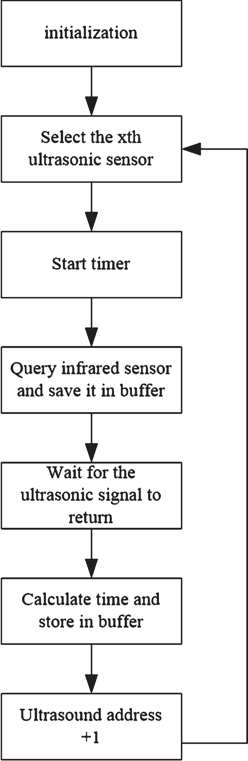
In Fig. 10, the ultrasonic sensor scans output of the infrared sensor at corresponding position, stops counter after receiving the reflected information of ultrasonic wave, and simply calculates reflection time of the ultrasonic wave and caches it into the buffer. After receiving the query instruction, it is fed back to the upper computer through the RS485 bus.
In the robot obstacle avoidance control unit, the electronic compass is an important part. Figure 11 is a flow chart of the electronic compass control software.
The operating process of electronic compass in Fig. 11 is as follows: the system is initialized, it is determined whether the bus instruction is a query compass, and if not, the system returns to initialization stage; if yes, a read instruction is issued to the compass. Then it is determined whether the compass sends back data related to obstacle avoidance. If yes, then add the data to the header of the packet and verify; if no, then determine whether the query is performed 10 times in succession. If the result is yes, then return to the system initialization stage; if the result is no, then determine if the bus instruction is a query compass. The iterations of the above process are repeated until all instructions are completed [20–23].
Control software flow chart of electronic compass.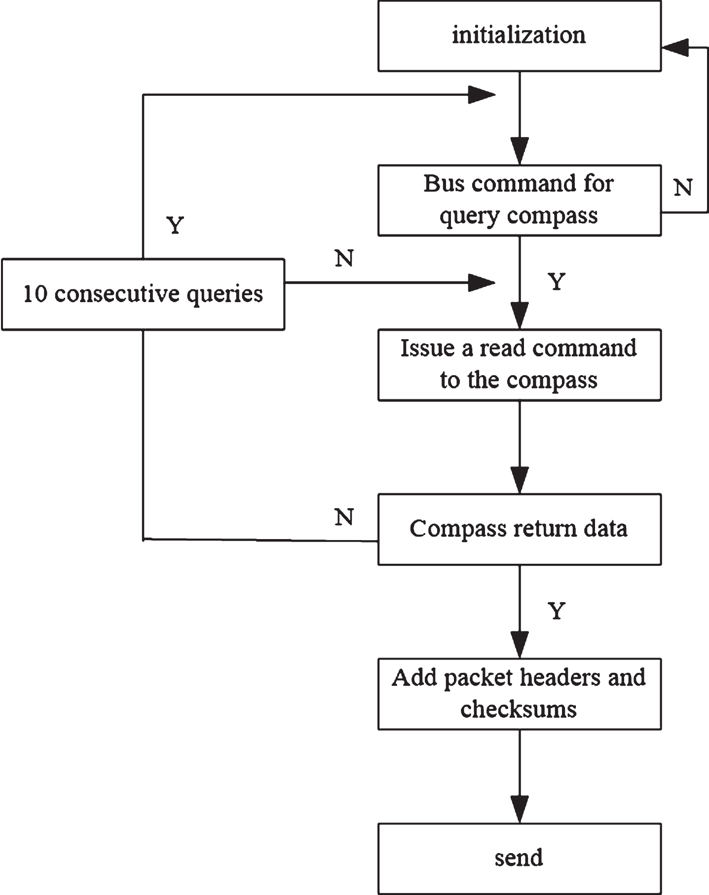
Overall, the software part of self-adaptive obstacle avoidance fuzzy system of mobile robots based on ultrasonic range measurement is composed of main control program, sensor information processing program and electronic compass control. The main control program realizes the robot’s self-adaptive obstacle avoidance by calling subroutines under different conditions. The sensor information processing software consisting of an ultrasonic sensor and an infrared sensor in the subroutine can accurately identify the position of the obstacle, when combine it with the electronic compass control program, obstacles can be avoided efficiently and accurately and all instructions can be completed.
In order to verify the feasibility of the self-adaptive obstacle avoidance fuzzy system based on ultrasonic range measurement for mobile robots, a test was conducted. Simulink is a visual simulation tool in Matlab that uses a modular editing method and a graphic editing language. In the Simulink environment, by using the mouse to drag the graphical module into the model window, a system simulation model can be easily built. According to the requirements of fuzzy control system operating parameters, Simulink fuzzy control module is utilized to design the simulation model. The Simulink Fuzzy Logic ToolBox is open, and the Fuzzy Logic Controller module is added, the module parameter setting dialog box will pop up by double-clicking the module. Then, the FIS file name generated by the fuzzy controller is written in the FIS File or Struckture window, and assumed as the AotoRobot in the experiment. The command AotoRobotl = readfis is run in the Command Window of the Matlab to establish the connection between the fuzzy inference system and Simulink.
The distance between the left and right obstacles is set as fixed values, and the distance of the front obstacle zone is gradually changed. The system outputs the target angle feedback control to adjust the robot moving direction. After compiling and running the model, the data stored in the simout module is the corresponding simulation data, which can be viewed in Matlab’s Workspace window. Then a target and several obstacles in different positions are set, and multiple tests are performed under the following test indicators:
Obstacle avoidance accuracy of robots Obstacle avoidance efficiency of robots Operation stability of obstacle avoidancesystem
The experimental results are as follows:
Analysis of Fig. 12 shows that the accuracy of path control obstacle avoidance based on improved hop search is low and the initial stage of obstacle avoidance is in good condition. However, as the distance is gradually extended, the robot continuously collides with the obstacles, and the phenomenon of poor obstacle avoidance accuracy appears. The obstacle avoidance accuracy of self-adaptive obstacle avoidance fuzzy system for mobile robots based on ultrasonic range measurement is relatively high. From the experimental results, it can be clearly seen that under this system, the robot can avoid obstacles accurately, and the accuracy rate can reach 100%. The proposed system is more scientific than the improved path control based on improved hop search.
Obstacle avoidance accuracy of robots in different systems.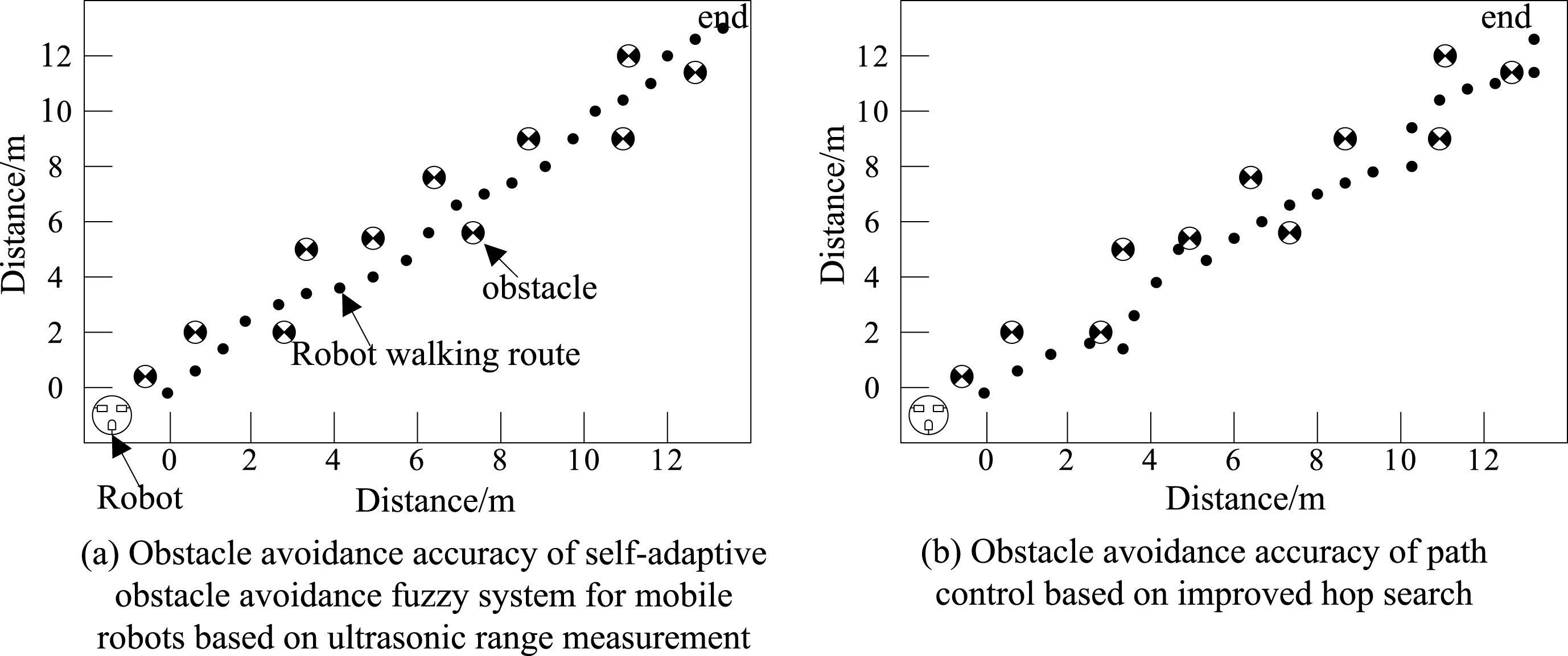
In Fig. 13, the obstacle avoidance efficiency curve of mobile robots based on optical flow is generally on the rise. The average time spent on obstacle avoidance is 0.65 s. The obstacle avoidance efficiency curve of the robot obstacle avoidance control system based on ARM and FPGA slowly rises in the initial stage. When there are 7 obstacles, obstacle avoidance takes a long time and shows a continuous growth trend. The average time for obstacle avoidance is 0.71 s. The obstacle avoidance efficiency curve of self-adaptive obstacle avoidance fuzzy system for mobile robots based on ultrasonic range measurement has a slowly increasing trend, and the average time for avoiding obstacles is 0.40 s. The proposed system is more reliable by comparing the results.
Obstacle avoidance efficiency of robots in different systems.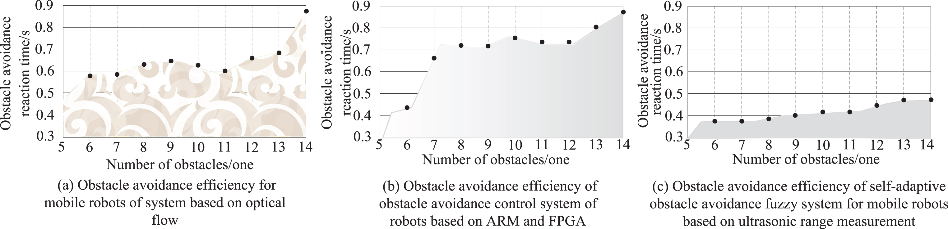
From Fig. 14, it can be seen that the obstacle avoidance stability coefficient curve of the system based on the improved artificial potential field rises steadily during the initial stage of system operation, but with the passage of time, the stability coefficient declines obviously. The obstacle avoidance stability curve of the system based on the survival area fluctuates greatly. When the running time is 0.8 h, the stability coefficient curve decreases linearly. The stability coefficient of the self-adaptive obstacle avoidance fuzzy system of mobile robots based on ultrasonic range measurement remains stable during the growth. Although it decreases slightly with the extension of time, it doesn’t affect the operation effect of overall system. Compared with current systems, it has obvious advantages.
Obstacle avoidance stability of robots in different systems.
In view of the various problems existing in the self-adaptive obstacle avoidance system for mobile robots, a self-adaptive obstacle avoidance fuzzy system for mobile robots based on ultrasonic range measurement is proposed. Considering problems existing in the current system, the selected motor model is D6015-30A, which has the characteristics of fast response, stable operation speed, etc., which can improve the system operation stability. At the same time, providing isolated power supplies for different functional components improves the anti-interference performance and can further enhance the stability of system operation. The ultrasonic range measurement, infrared range measurement and electronic compass are combined to improve the obstacle avoidance accuracy and efficiency of the self-adaptive obstacle avoidance system. The following points are proposed for future plan.
The mechanical design of the mobile robot can be designed even smaller, which can not only increase the flexibility of the robot motion but also reduce the power consumption.
The next step is to conduct in-depth research on information fusion and path planning for ultrasonic-navigated mobile robots.