
Abstract
This study reviewed efficient bridge management using UAVs (Unmanned Arial Vehicles) that have much potential for facility maintenance such as the possibility of regular inspection on inaccessible parts of bridges, easy operation regardless of the operators’ specialty, and economic maintenance. For this study, images were obtained from a UAV and a 3D viewer was created with them for the work efficiency of bridge inspectors, so that the inspectors can see and check inaccessible areas regardless of inspector’s location. It compared various existing inspection methods for problems such as cracks, efflorescence and leakage with the UAV inspection method to analyze the work efficiency as well as sustainable economic benefit. The main purpose of this study was to figure out whether the proposed inspection using the images from the UAV and 3D viewer can replace the existing inspection methods that cannot be performed easily and analyze the economic benefit of the new method. The study result showed that the UAV image-based bridge maintenance and inspection is possible even though it was found inefficient when images of uneven quality were provided depending on operation of the UAV. Therefore, a UAV operation manual that can help generate images of even quality must be produced.
Introduction
Bridges are an important SOC (Social Overhead Capital) closely linked with public safety and vital social and economic infrastructures that are indispensable for economic activity and transportation logistics. There are 30,983 bridges used in total as of the end of 2015 in South Korea and the number is increasing. This implies that construction technologies for the bridges reached a significant level with lots of attempts and efforts to develop new construction technologies, materials and patents. However, increasing traffic stemming from rapid economic growth also damages the bridge structure in the long term [1].
It must be a serious issue for the bridge maintenance and will be difficult to keep the function of the existing bridges unless close attention is paid to the bridge maintenance after completion of construction. Man-made accidents that keep occurring one after another recently and people’s decreasing awareness on safety make it urgent to secure safety on public SOC infrastructures. In particular, bridges serve the public purpose much more than other infrastructures and have a significant impact on the people and national economy if an accident takes place. The infrastructures in South Korea that were largely built during rapid economic growth in the 1970 s and 1980 s are more than 30 years old and their deterioration rate exceeds 11.1%. If the old infrastructures are not maintained and inspected systemically and periodically, the efforts to build a national safety net will be challenged greatly. Reducing people’s safety concern about the old infrastructures and responding to an evolving technological environment systemically requires efforts of the related field and continued investment in the long run. Entering the era of deteriorating infrastructures, the country is expected to have 9,576 bridges (30.9%) that are older than 30 years in a decade and 21,737 bridges (70.2%) in two decades as of December 2015. In the US, 503 bridges collapsed in the last 11 years and 250 trillion won was spent for their management. The Ministry of Land, Infrastructure, Transport and Tourism of Japan established a long-term plan to conduct regular inspection on urban infrastructures and bridge maintenance [1–3]. As the example shows, their performance and life should be improved and financial burden should be eased through systemic maintenance and inspection from the long-term perspective and the public safety and service quality should be enhanced to effectively address the rapid increase of aging bridges. Despite the above-mentioned reason, bridge maintenance and inspection in reality face many problems due to the limitations of methodology and system. As Fig. 1 shows, the existing inspection method entails cost, time, traffic control and subsequent traffic jam, and worker safety issues as they need expensive equipment such as an inspection vehicle and many workforces. Besides, time series analysis on or monitoring of bridge deterioration such as delamination, spalling and crack is difficult since simple inspection lists and pictures only are kept as bridge inspection results, which makes it difficult to precisely match the pictures with the bridge drawings.

Limitations of current inspection work.
When special bridges are inspected, cables, pylons and essential members may interrupt access of the equipment and structural members may interfere with and be damaged by the inspection equipment. The inspection vehicles may not access bridges in the city because of sidewalks or street lights or repeated installation and removal of a telescopic boom will reduce work efficiency. If a new inspection paradigm cannot be developed, such inefficiency and ineffectiveness will continue.
This study investigated ways to carry out efficient bridge maintenance and inspection with UAVs that have the potential to address such limits and challenges, enable regular monitoring, bring economic benefit and facilitate operation.
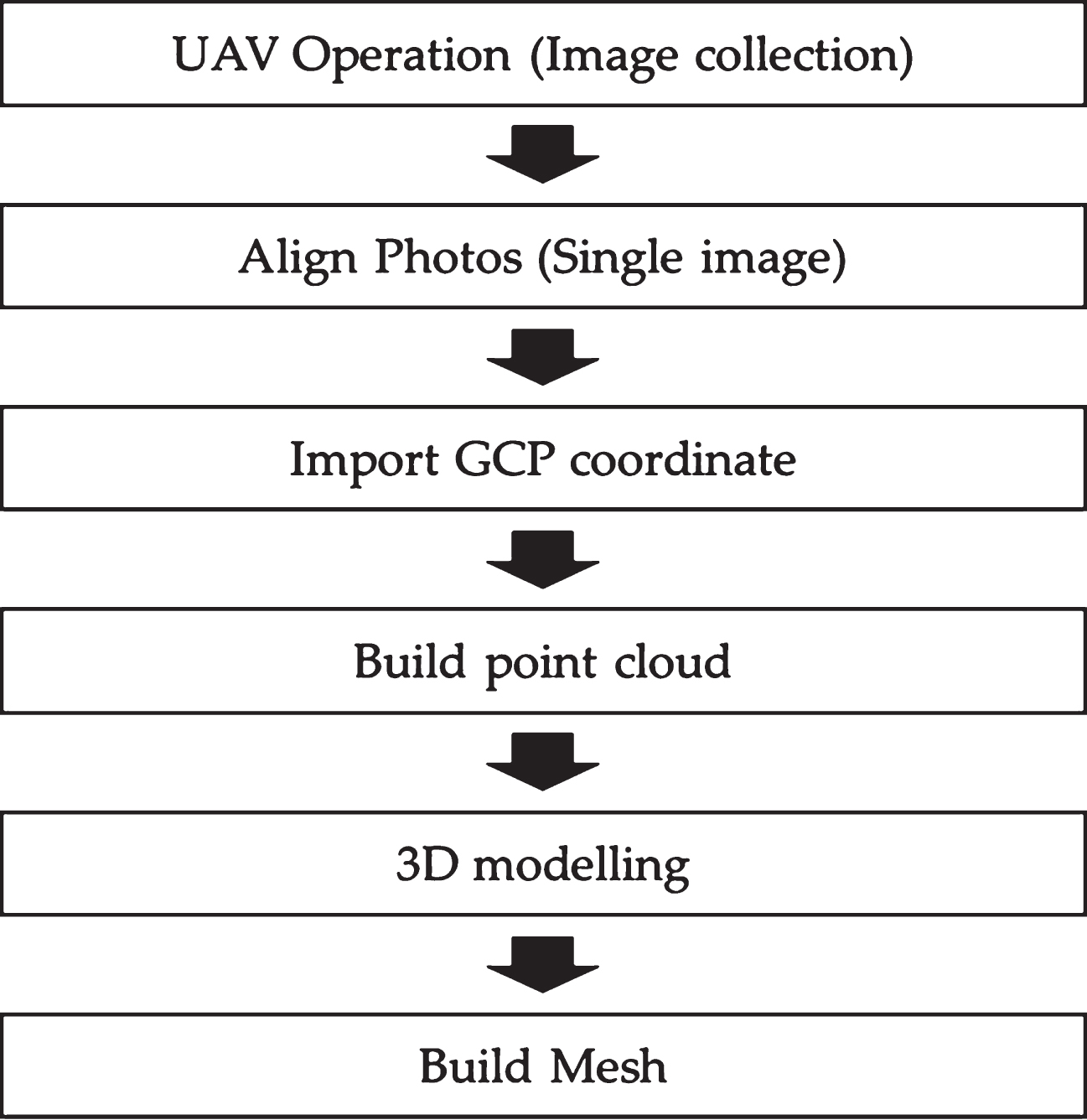
To achieve these goals, Test Bridge named Wonju Bridge was considered, obtained UAV images and performed a 3D modeling based on the UAV image-analysis as described in Chapter 2. Furthermore, a 3D viewer was created to help bridge inspectors intuitively understand and inspect bridges. An inspection checklist is derived in Chapter 3 to enable the bridge maintenance and inspection through the 3D viewer based on the UAV images by referring to the existing bridge inspection checklists. The bridge maintenance and inspection method using the UAV images is analyzed and compared with the existing methods and the economic feasibility of the proposed method is analyzed in Chapter 4. Lastly, a conclusion of this study is drawn in Chapter 5. Figure 2 shows the entire workflow of this study.
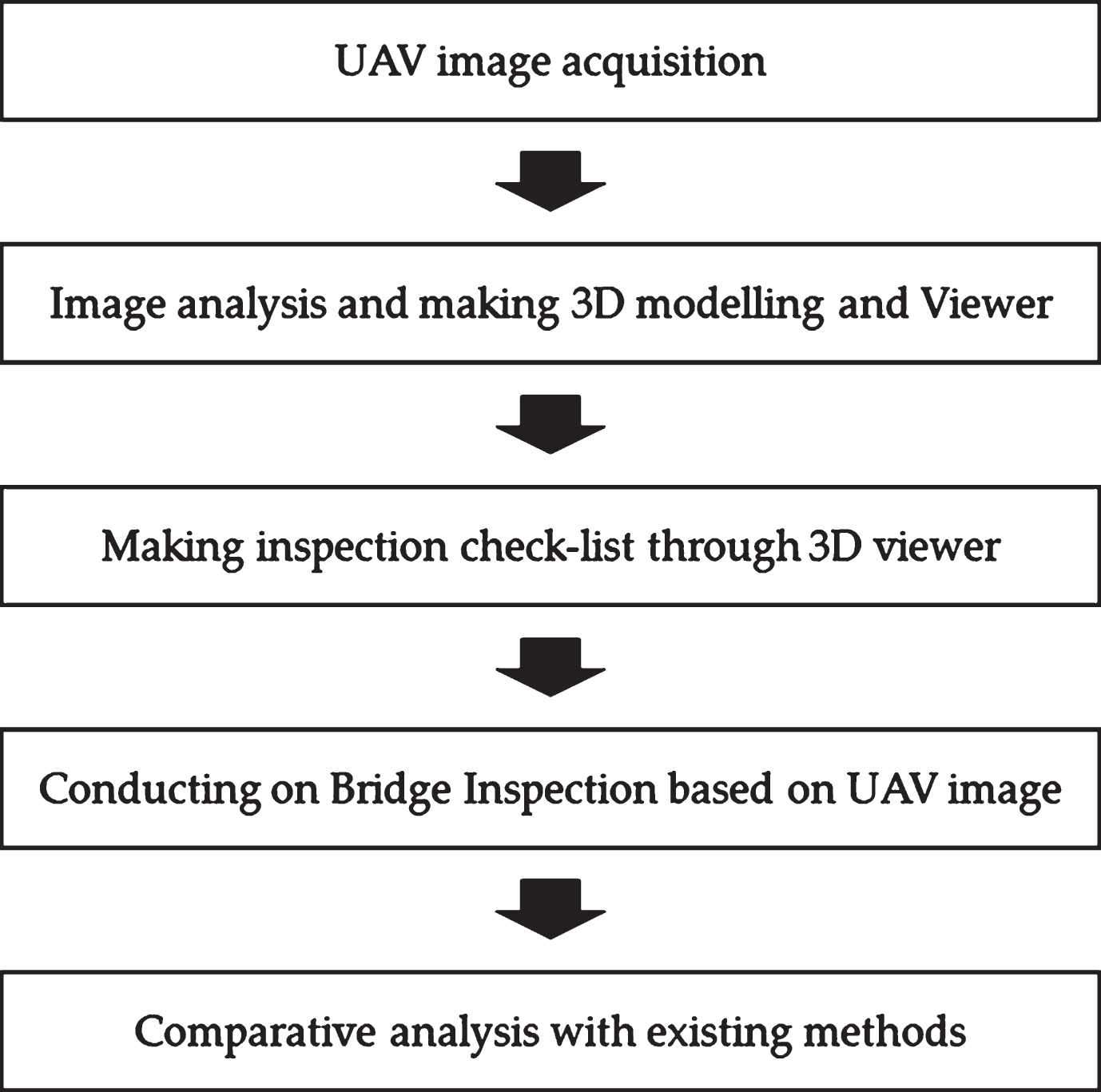
Workflow of this investigation.
Selecting the test-bed
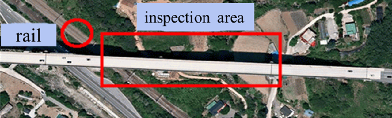
Wonju Bridge located in Panbu-myeon, Wonju, Gangwon Province was selected as the subject of this study. Built in 1995, the superstructure of the bridge is a steel box girder type with two-bay box while the substructure has 11 piers of T-type and Π-type. For this study, only Piers 2 to 4 were measured. The target section was 160 meters between Pier 2 and Pier 4 out of the 640 meters of the entire bridge and the height of each pier was about 45 meters. Multiple obstacles were found near the bridge during the pre-survey. Utility poles generated magnetic fields and interfered with the UAV’s flight route. They could also affect receiving GPS signals. These factors should be taken into consideration through the pre-survey to set up the UAV route.
UAV image collection and processing
Establishing a flight plan and measuring the ground control points (GCPs)
The flight plan (flight route) was established in consideration of appropriate photographing altitude, camera angle of view and flight route to observe members, overlap and sun’s position to obtain the images. AiProFlight of Aibotix was used for the ground control system (GCS) such as establishing the flight route. Figure 3 shows the UAV flight plan setup.
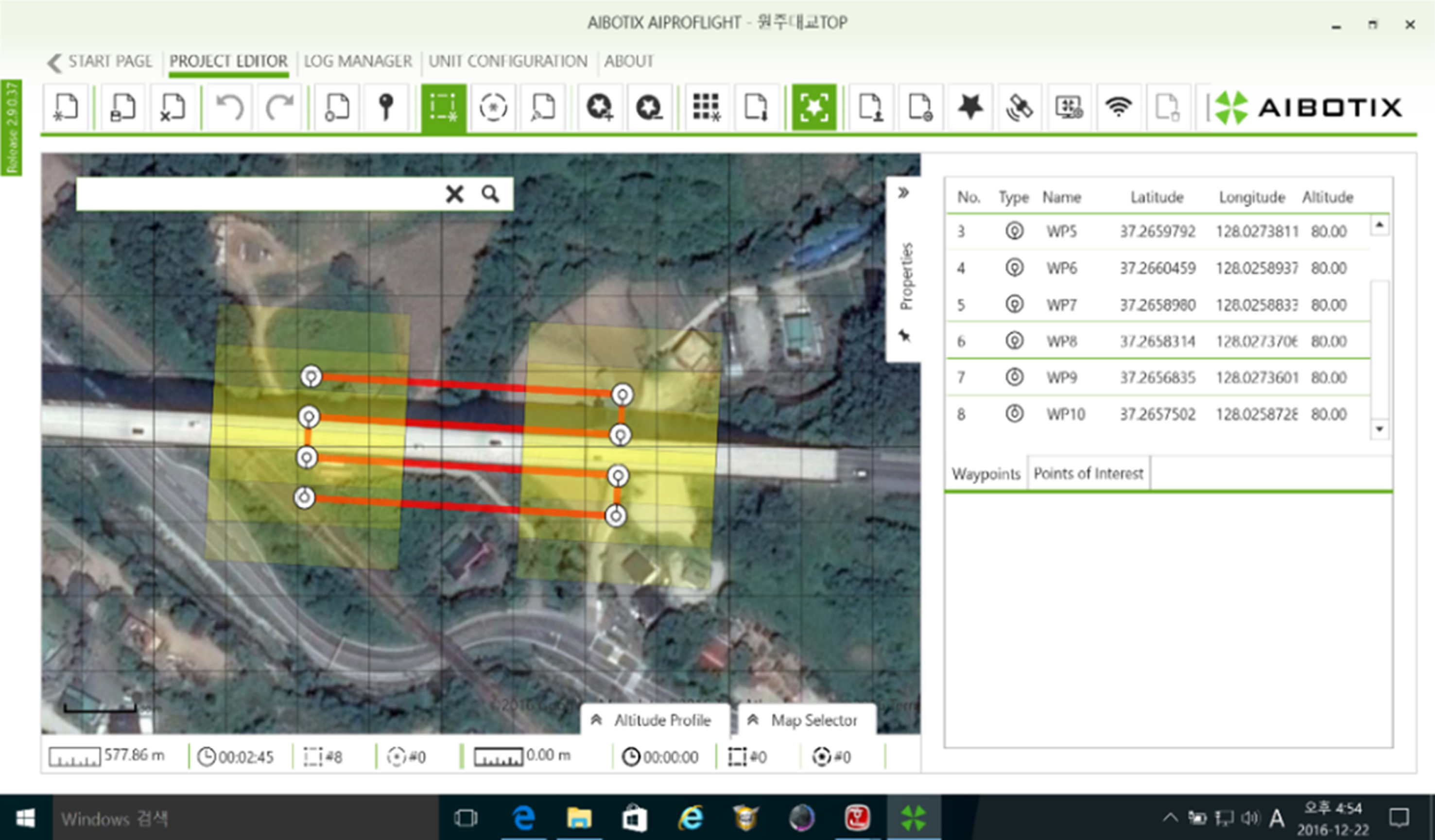
Setting UAV flight plan.
Three and eight GCPs were installed on the superstructure and substructure of the Wonju Bridge respectively before collecting the images to improve positional accuracy during image matching. The GCPs were observed through VRS positioning. Figure 4 and Table 1 show the installations, positions and coordinates of the GCPs.
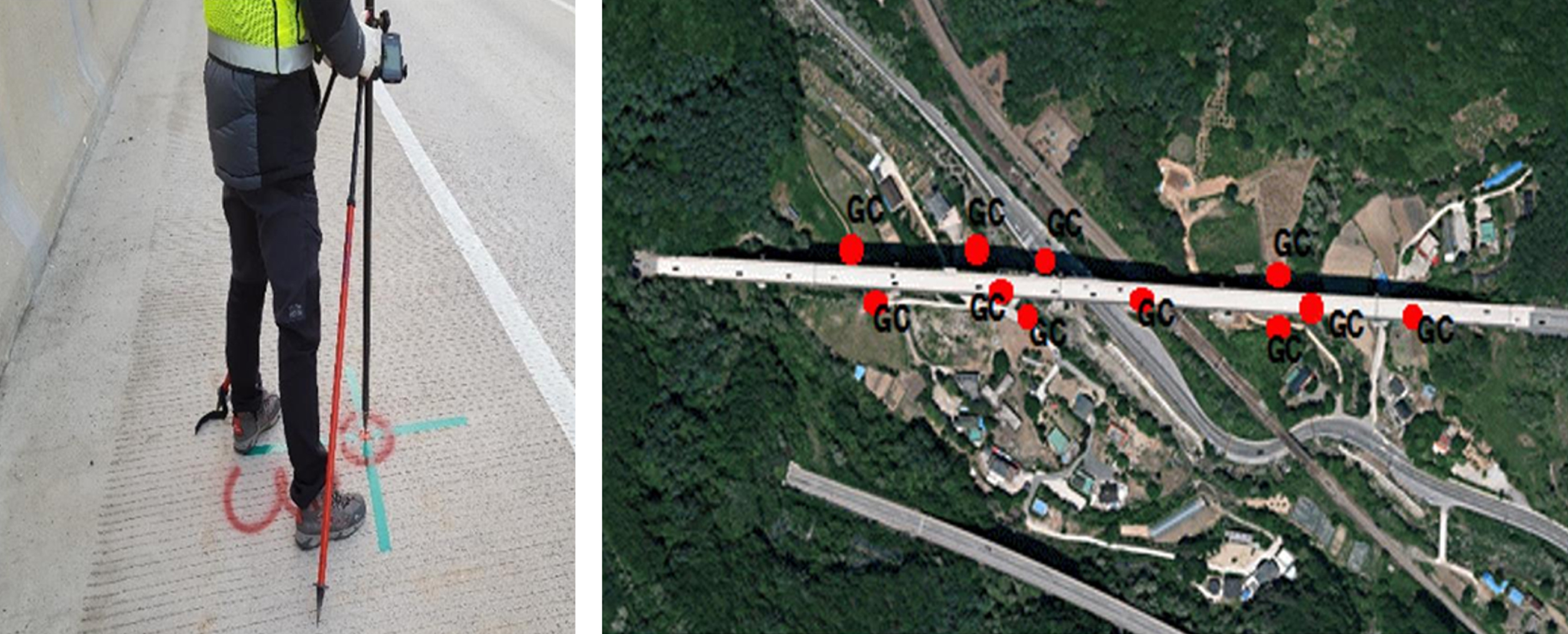
GCP surveying and installation position.
GCP coordinates used
Table 2 shows the specification of the UAV used for the study, which is Aibotics of Leica. The product was developed to inspect infrastructures such as bridges. The biggest difference from other UAVs is that the photographing scope can be greatly extended by installing an on-top gimbal.
UAV specifications
UAV specifications
UAV operation and image collection.
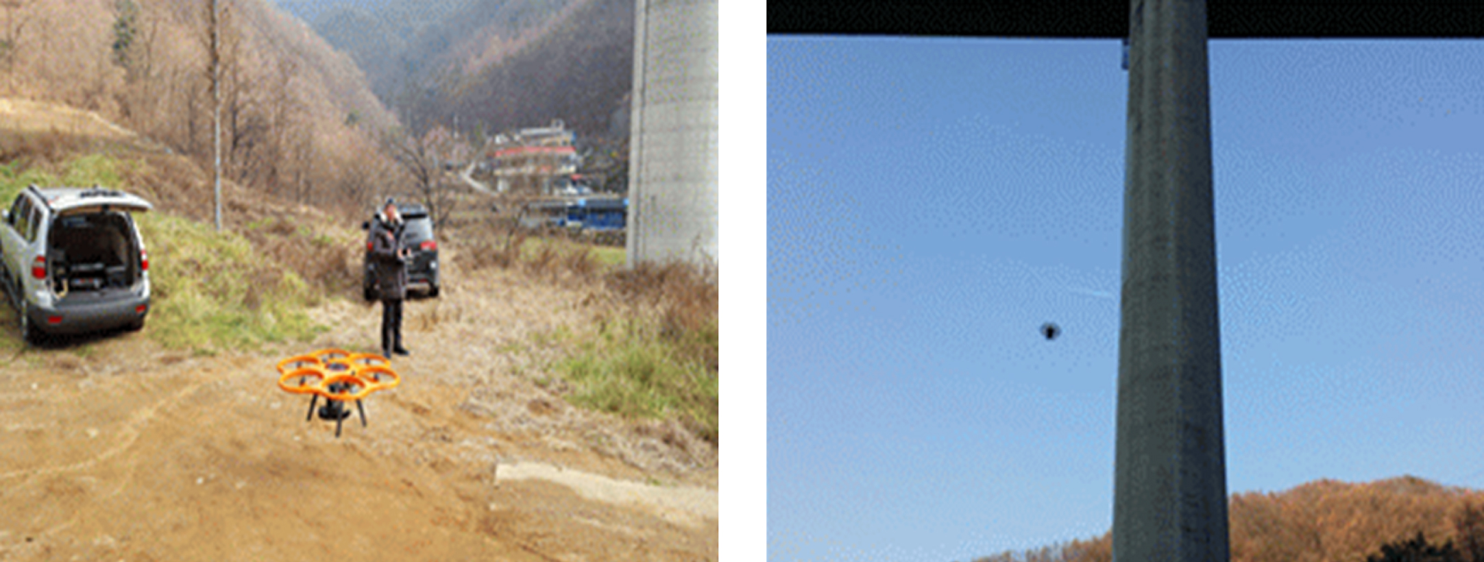
UAV-based inspection was carried out for two hours from 8:00 A.M. on November 20 and December 8, 2016, respectively. The UAV was flown after establishing the flight plan and installing the GCPs. The flight took place in the morning to avoid environmental factors that can arise from the air current heated by the ground. Photographing in the morning can also help minimize the shadow and noise of the images caused by backlight and the effect from data diffusion as more sunshine brings faster wind. About 500 images were obtained from the UAV operation (Sony 7RII, 52M-Pixel). Figure 5 shows the UAV operation and image collection.
The PIX4D Mapper software was used to process the obtained images, and image matching and 3D modeling analysis was conducted. Following the data input of the collected images and the selection of WGS84 coordinates, the model and characteristics of the camera used for photographing are input and the modeling is analyzed. Figure 6 presents the flowchart of overall image matching process [4].
Process for image matching.
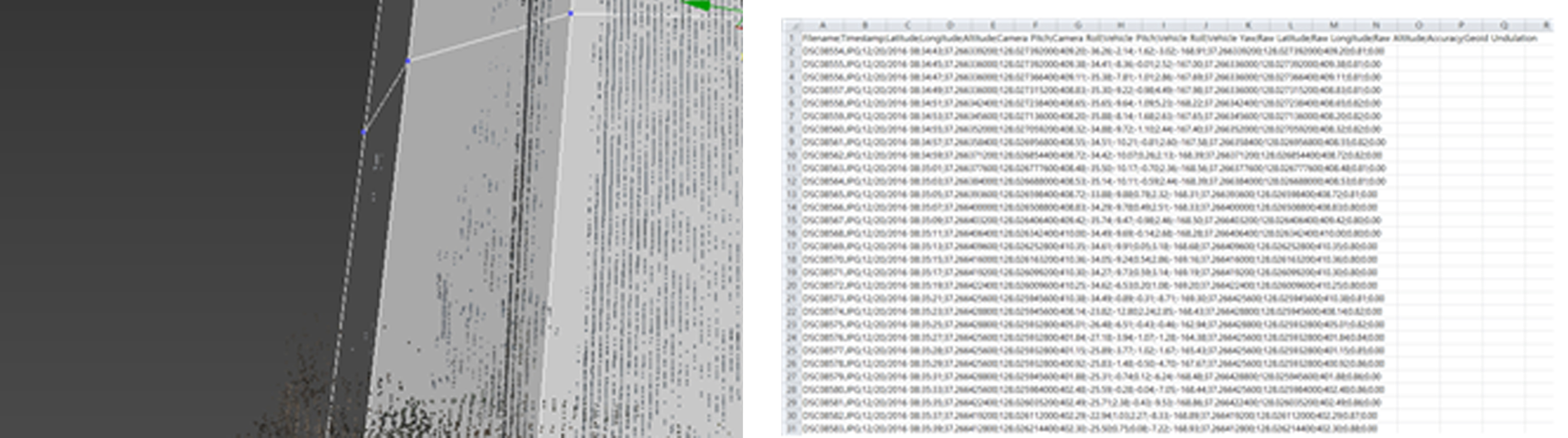
After the UAV image matching is finished according to the analysis procedure, image matching must be analyzed and it should be verified whether complementary photographing is needed for any uncovered members among the major members of the bridge with the route of images taken by project files and actual single images photographed. For this purpose, the image matching is verified and the mismatching locations are analyzed. Figure 7 shows this process.

Checking the UAV flight route and image matching.
After analysis of the image matching and uncovered areas, the GCPs were input and 3D image matching and modeling were performed subsequently as shown in Fig. 8. The coordinates of the GCPs already installed were input during the image matching to carry out the 3D image matching and the 3D modeling was executed through this.
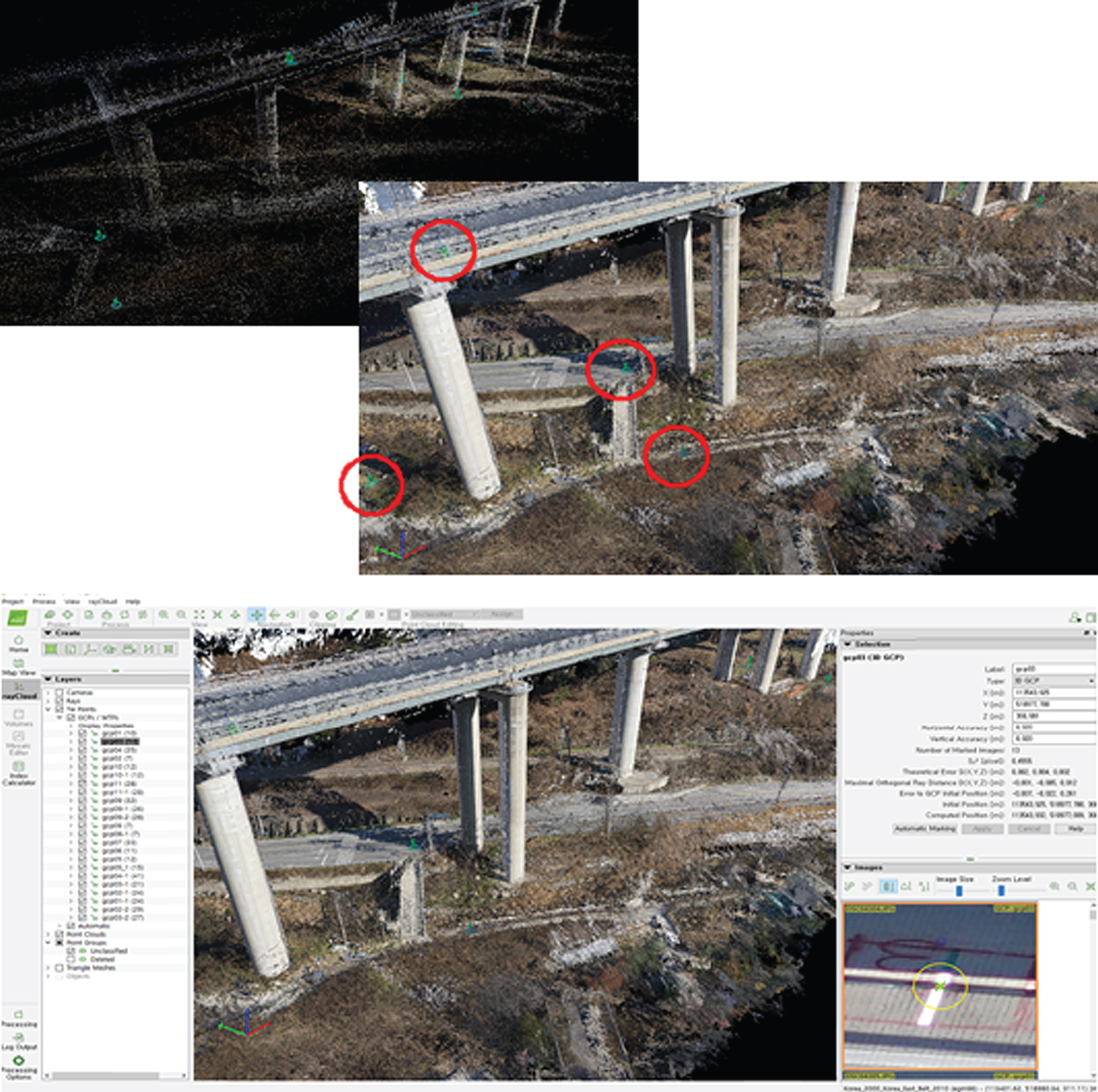
Input process of GCPs.
The image matching and 3D modeling of the bridge was performed and the result is shown at Fig. 9. Then, point cloud data filtering was performed to create the 3D viewer using the generated 3D modeling. The point cloud data could be obtained before the image matching and noisy point cloud data caused by reflecting and transparent objects (glass and water, etc.) could be removed in this process. This improved accuracy and sharpness of the resulting image matching. Besides, filtering of good point cloud data could be performed when the 3D modeling was visualized and the viewer considering user convenience was created [6].

Results of image matching.
The 3D viewer of this study was created to help the bridge inspectors intuitively know the subject members and their positions in the bridge and efficiently check damages of the members and manage the records. It was created using the point cloud through image matching analysis for inaccessible members along with the bridge measurement data to perform the modeling that forms the basis of the 3D viewer. The preprocessing to create the viewer included ding172 interpolation of filtered point cloud data and work on noise (Figs. 10, 11); ding173 bridge measurement data check and additional interpolation (Fig. 12); ding174 application of images of the filtered modeling data (Fig. 13); and ding175 installation and use of the viewer system (Fig. 14).

Editing point cloud data and separating works.

UAV Image matching.
Verification of matching between point cloud data and modeling data.

OBJ file extraction (output) and 3D viewer program.
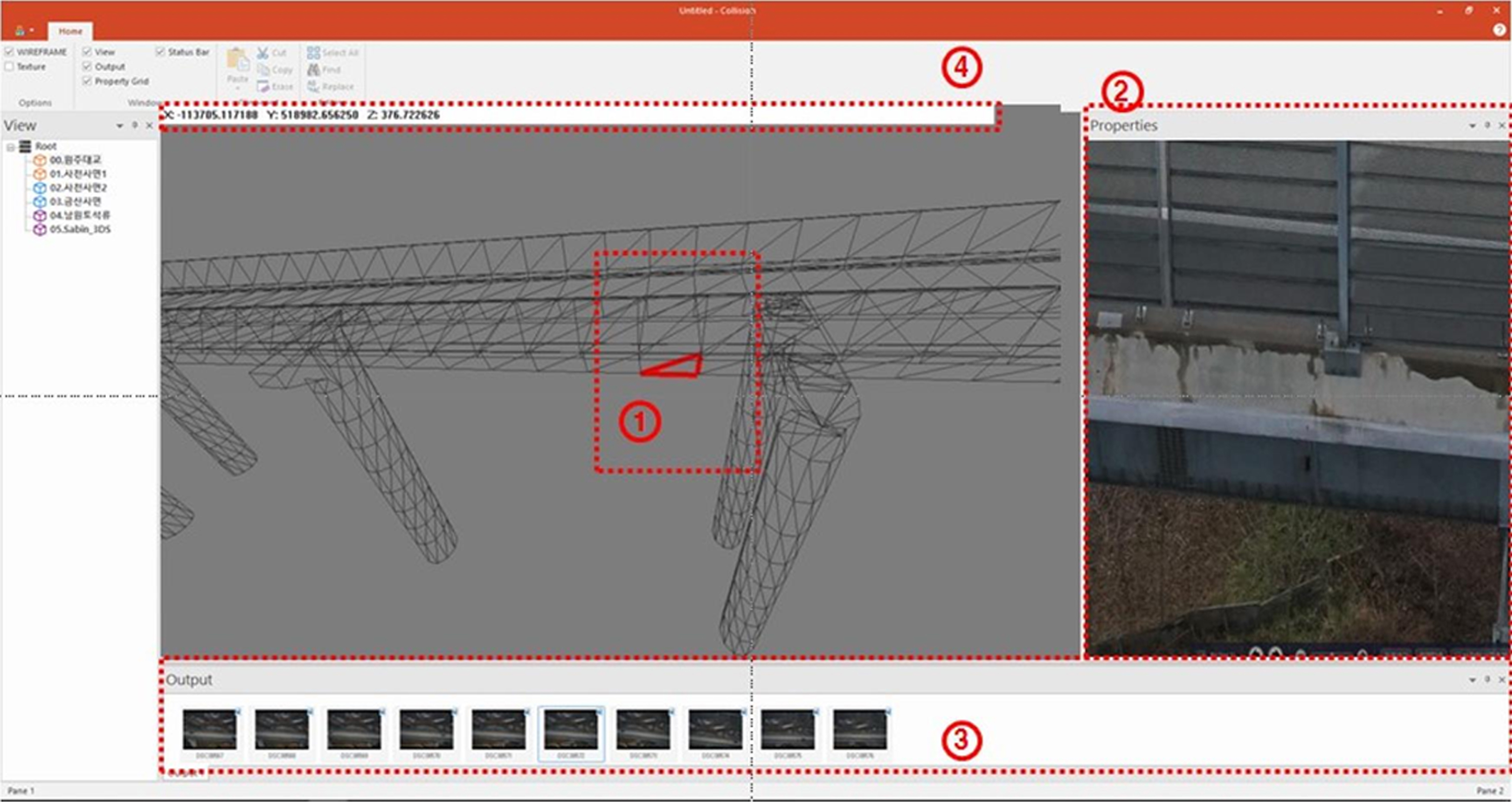
Viewer implementation.
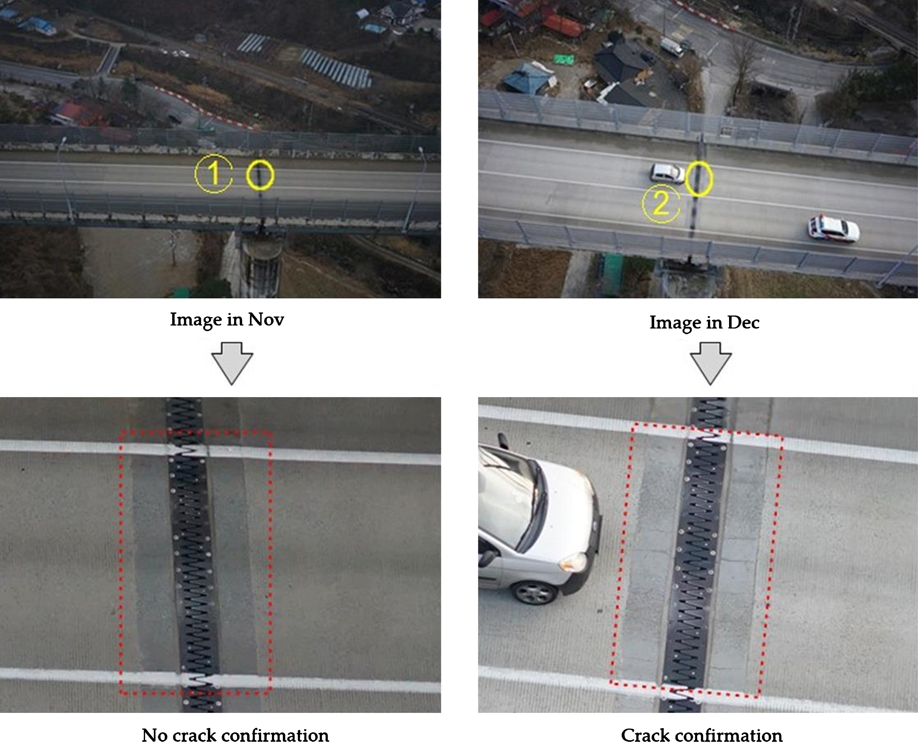
An inspection checklist was prepared based on the existing inspection and management items to inspect the bridge with the implemented 3D viewer and the possibility of performing inspection with the UAV images was checked for each item. As Fig. 15 shows, the same members were photographed, but the results differed depending on the date.
3D viewer.
Large cracks (mm) could be observed when the UAV images were obtained in good weather. The images of the same position sometimes showed different damages. The image of November shows that the bridge rail was wet while that of December shows that it was almost dry. As shown in the above figure, different environmental conditions for UAV operation could bring different results for the possibility of damage survey. Figure 16 illustrates cracks, breakage, steel corrosion caused by leakage, contamination and efflorescence observed with the single images of the 3D viewer.
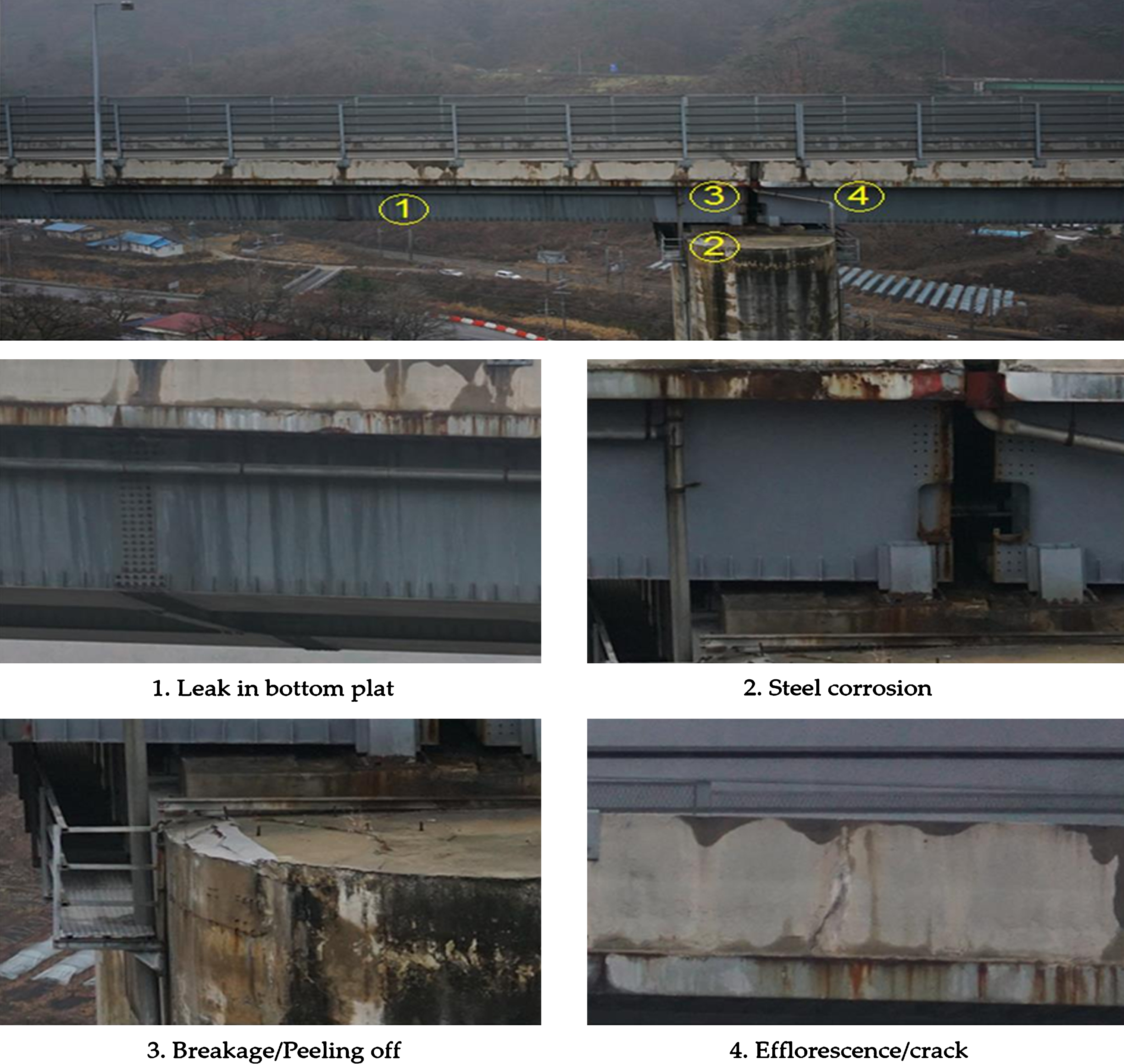
Inspection of steel corrosion, contamination and efflorescence.
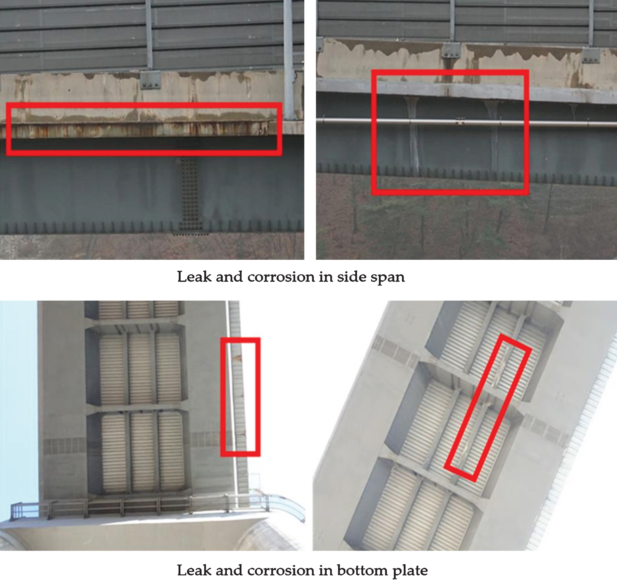
Steel leakage and cracks (estimated to be several millimeters) were also surveyed with the 3D viewer. Figure 17 shows the inspection result.

Inspection of leak in bottom plat and efflorescence.
In addition, cracks could be identified with a close-up of the member (within 5 m) as Fig. 18 shows.

Identified crack.
Generally, cracks are repaired when they are 0.3 mm or wider. The crack of the image above was estimated to be more than 0.3 mm because traces of repair were found above and below the crack. Therefore, it was estimated that cracks of 0.3 mm or wider could be found with a close-up. However, the precise measurement of crack width would be impossible with the images. On the other hand, this survey took long time and it was impossible to identify the location of damaged parts when the GPS signal from above the bridge was blocked (Fig. 19).

Inspection of the bridge substructure when GPS signal was blocked.
Girders and bottom of the deck could be photographed by a single image. However, inspecting the deck bottom with a current commercial (GPS signal-based) UAV solely relied on the skill level of a pilot (manual control). As a result, complex members of the girder bridge such as crossbeams and stringers caused blind spots and many mismatches occurred during the image matching [4].
The members that can be inspected using the images photographed by the UAV are listed in Table 3. Damages that had obviously different colors or textures from other parts such as leaks, efflorescence of cracks, contamination and breakage could be inspected from a distance. Cracks of around 0.3 mm could not be observed when they were photographed from a distance. It was relatively easy to find cracks of several millimeters. It was difficult to find them, however, when it was raining or wet or the illumination of photographed area was very high.
Checklist
 ∘: possible, ×: impossible, Δ: possible but accuracy needs to be confirmed, –: not for consideration.
Comparison with existing method
Visual inspection is a basic inspection work in the regular and detailed inspections, and is an important element in assessing the facility condition. The on-site inspection items of the detailed inspection typically consist of visual inspection and non-destructive inspection. Assessing the condition through visual inspection is considered first since it is the greatest factor affecting the final result. The visual inspection is performed basically by walking or with simple equipment such as ladder. The inspectors use a telescope or telephoto lens to assess the condition when it is impossible to access them. However, this also allows limited observation or inspection when the facility is a long span bridge. When the members are inaccessible, the inspection is performed with the equipment in Fig. 20.
An aerial lift truck has a relatively little limit for elevated work but is less efficient than the bridge inspection vehicle. Besides, it is hard for the aerial lift truck to approach the riverbed. Meanwhile, it is difficult to inspect bridge bottoms with the bridge inspection vehicle as its mobility to the bottom part is limited, which would likely result in a poor inspection without using additional equipment. Figure 21 shows inspection sampling results on a few members of Wonju Bridge along with the aforementioned cases.
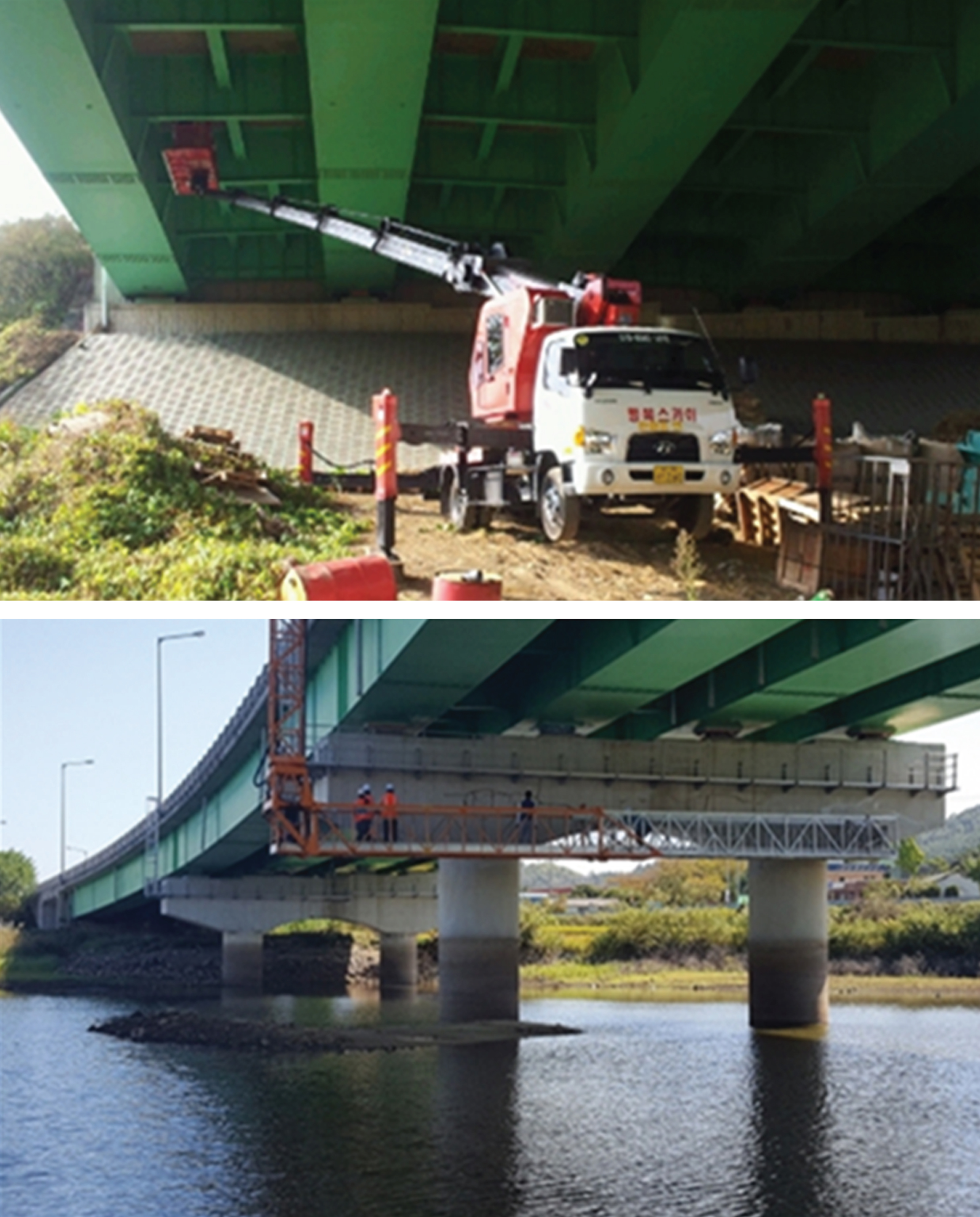
Current bridge inspection methods.
Analysis of UAV images showing bridge bottom plate.
Among the examples shown in the figure, the cracks are highlighted in red lines. When the original images were magnified, the cracks were observed more clearly. As the images show, most damages of key members could be inspected. Though it was difficult to inspect narrow parts such as shoes, human inspectors could access them in person if an inspection path was installed. Inspection using a UAV was insufficient to measure the degree of damages, that is, the precise area and length of damages. However, the size of damages could be measured with a relative scale of the subject facility if its dimensions were known. The required workforce and inspection time of the existing method were compared with those of UAV-applied inspection for the selected 160 m section of Wonju Bridge by using the equipment and applying the regular inspection method.
Although the thorough inspection of all members of the bridge was still insufficient, inspection using the UAV was found very effective. An alternative to this was required since follow-up works such as producing external GIS after inspection were not linked with this. However, work efficiency should be enhanced in various aspects like accessibility and convenience to inspect the bridge as well as objective inspection by a third person with obtained images other than inspectors. Table 4 shows the comparison and analysis result.
Comparison and analysis of existing method and UAV inspection method
The economic feasibility of using the UAV-based inspection was analyzed for certain members. The analysis was limited to the required time, workforce and cost required to perform tasks that are easy to measure in the unit of currency as a basic inspection. Table 5 explains the analysis.
Economic feasibility analysis
Economic feasibility analysis
A precondition of general economic feasibility analysis is that the analysis result should be the same. However, this study presented different results. Human workforce could identify fine cracks (0.1∼0.2 mm) while the UAV failed to inspect fine cracks or cracks with 0.5 mm or smaller width. The UAV images did not include image matching and were the result of single image photographing. The time required was based on a 500 m bridge, the UAV rental cost was based on the quotation of a general photographer and the photographing cost was based on a day. In the meantime, the labor cost was calculated according to the payment standard for skilled engineers [7].
This study verified the efficiency of a bridge inspection using a UAV that can be applied to various fields including emergency and safety to address the actual limitations of bridge maintenance and inspection. That is, it was checked whether cracks, efflorescence and spalling on certain members of the bridge such as the pylon and bottom plate to which access by human inspectors was difficult could be inspected with the UAV images. A 3D viewer was created to allow the inspectors to efficiently inspect the bridge no matter where they were. A checklist showing the members that could be inspected with the UAV images was created by using the 3D viewer. The checklist described that most members could be inspected such as surface pavement, barrier/rail, expansion joint, cracks in the drainage system, leakage, surface breakage and structural defect. Then, the economic feasibility of using the UAV was analyzed to figure out that the proposed method was more cost efficient in the aspect of time and workforce needed than the existing method.
This study found that the quality of the UAV images significantly affected the entire bridge inspection and regular updates at certain times should be possible due to the nature of the inspection work. This implied that producing homogeneous image quality with the existing images could be the key to an efficient UAV-based inspection. To achieve this goal, a UAV operation manual and work regulation must be created in the future.
Footnotes
Acknowledgments
This research was supported by the Ministry of Land, Infrastructure, and Transport in Korea under the Urban Planning and Architecture (UPA) research support program and was supervised by the Korea Agency for Infrastructure Technology Advancement (KAIA).
Project number: 18DRMS-B147287-01.
Project name: Development of customized realistic 3D geospatial information update and utilization technology based on consumer demand.