



Abstract
In this study, a four-degree of freedom (4-DOF) robot arm uses an innovative two-dimensional vision sensing method to grip a moving target on a moving platform. This study utilizes forward and inverse kinematics to establish a dynamic model of the 4-DOF robot arm. A computer as a controller and a single charge-coupled device (CCD) calculates the two-dimensional vision sensing method and sends commands to an Arduino Uno microcontroller to drive the robot arm. According to simulation results of transient and steady states in MATLAB SimMechanics, the response of the dynamic proportional-fuzzy controller is better than the response of proportional–integral–derivative controller. To demonstrate a precise control of the point-contact grip, this study utilizes a ping pong ball as a target on a moving platform. Using the dynamic proportional-fuzzy controller based on the two-dimensional vision sensing method, the 4-DOF robot arm can position, grip, and carry a moving ping pong ball to a designated place in three-dimensional space, which breaks through the previous two-dimensional limitation using a single CCD. This breakthrough can reduce the weight and cost of the robot arm. Therefore, this study aims to utilize the technology to grip moving targets on a moving platform for manpower cost reduction in the industry or agriculture domain in the future.
Keywords
Introduction
With a population trend of fewer children and more elderly people, meeting the labor demand will be a major challenge for labor-intense activities like harvesting crops and handling goods. Companies are also looking for solutions to issues such as how to effectively reduce cost, raise market competitiveness, and increase capability. Using automatic robots to replace human beings in harsh working environments is the trend of the future [1], and robot arms are the most popular application in the robotics industry. For robotic applications, the multi-link robot arm is used in highly repetitive, dangerous, or time-consuming cases such as in automotive manufacturing [2], fruit harvesting [3], and sample collection in outer space or abysmal sea [4]. The accuracy of the position control is the most important feature for a robot arm. According to the literature, most of the robots or robot arms usually receive the position information by a global monitor, two charge-coupled devices (CCDs) [1, 6], or a CCD with a laser sensor [3].
In this study, a four-degree of freedom (4-DOF) robot arm is combined with one CCD and it uses an innovative two-dimensional vision sensing method to calculate the relative position between the robot arm and the target in three-dimensional (3D) space. The 4-DOF robot arm is automatically instructed to grip a target on a moving platform using, first, a proportional-integral-derivative (PID) controller, and second, a dynamic fuzzy-proportional controller. To demonstrate precise control of the point-contact grip, this study utilizes a ping pong ball as the target on the moving platform. The robot arm can successfully position, grip, and carry a moving ping pong ball to a designated place in three-dimensional space, which breaks through the previous two-dimensional limitation using a single CCD. The success of this study demonstrates this technology, to grip moving targets on a moving platform, and reduce manpower costs in industry or agriculture. The companies using this technology can not only improve work efficiency during busy situations but also reduce cost, and raise their market competitiveness.
4-DOF robot arm system
The 4-DOF robot arm system automatically grips the target on the moving platform as shown in Fig. 1. A computer using MATLAB software as a controller is integrated into forward and inverse kinematics theories [7] for path planning of the robot arm system. The computer sends control commands to an Arduino Uno microcontroller to drive five servo motors (Joints 1 to 5) of 4-DOF robot arm, shown in Fig. 2. The Joint 5 servomotor only controls the grip.
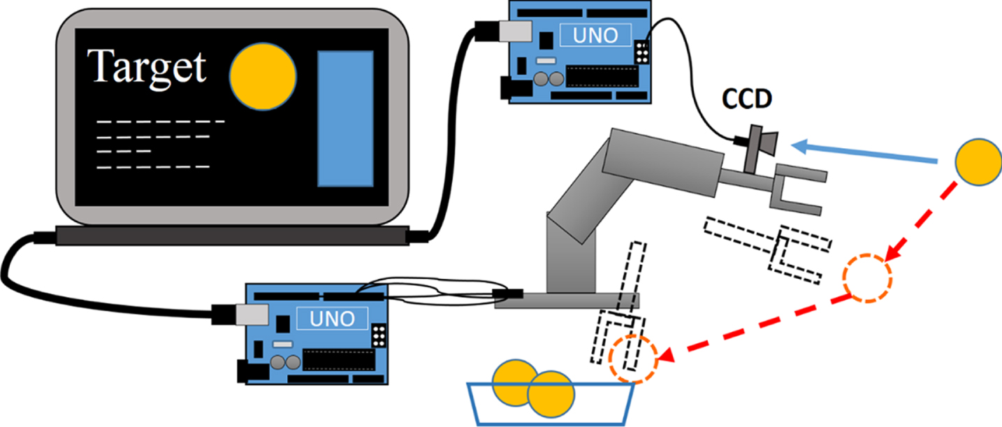
Schematic diagram of 4-DOF robot arm system.

Joints of the 4-DOF robot arm.
This study only utilizes one CCD, a Pixy CMUcam5 sensor as shown in Fig. 2, to obtain the feedback position signals from the Arduino Uno board of the target as it rests on a moving platform shown in Fig. 3. The platform is driven by a 28BYJ-48 stepper motor. A Vl53l0x laser distance sensor is used to record the target position on the moving platform. Figure 4 depicts the 4-DOF robot arm system with a monocular vision sensor. SolidWorks, MATLAB Simulink, and SimMechanics software are used to simulate and analyze the dynamics of the 4-DOF robot arm system.
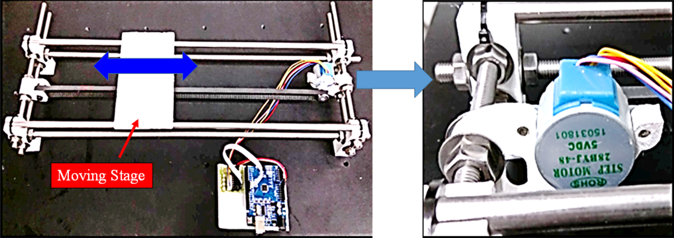
Moving platform.
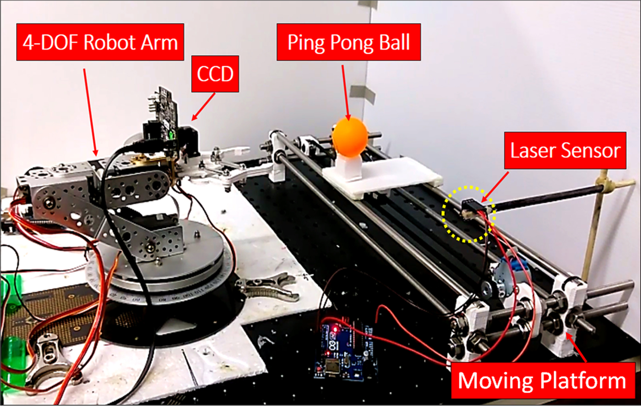
4-DOF robot arm and target system.
A single CCD is limited to measuring positions in only two-dimensions. This study creates a new vision sensing method to measure the three-dimensional position of the target using only a single CCD, which the new vision sensing method is based on the changes in the number of pixels in the field of view (FOV) of the CCD, as the distance between the target and the CCD changes. In Fig. 5, the width of the target is the same before and after the CCD moves a distance, α. Using the ratio of pixels in the FOV of the CCD allows the distance between the CCD and target, x, to be derived as shown in Equations (1 and 2).
In Equation (1), n and m represent the ratio of the number of pixels of the width of the FOV divided by the number of pixels of the width of the target before and after the CCD moves the distance α, respectively. Solving Equation (1) for x gives the distance between the CCD and the target, seen in Equation (2).
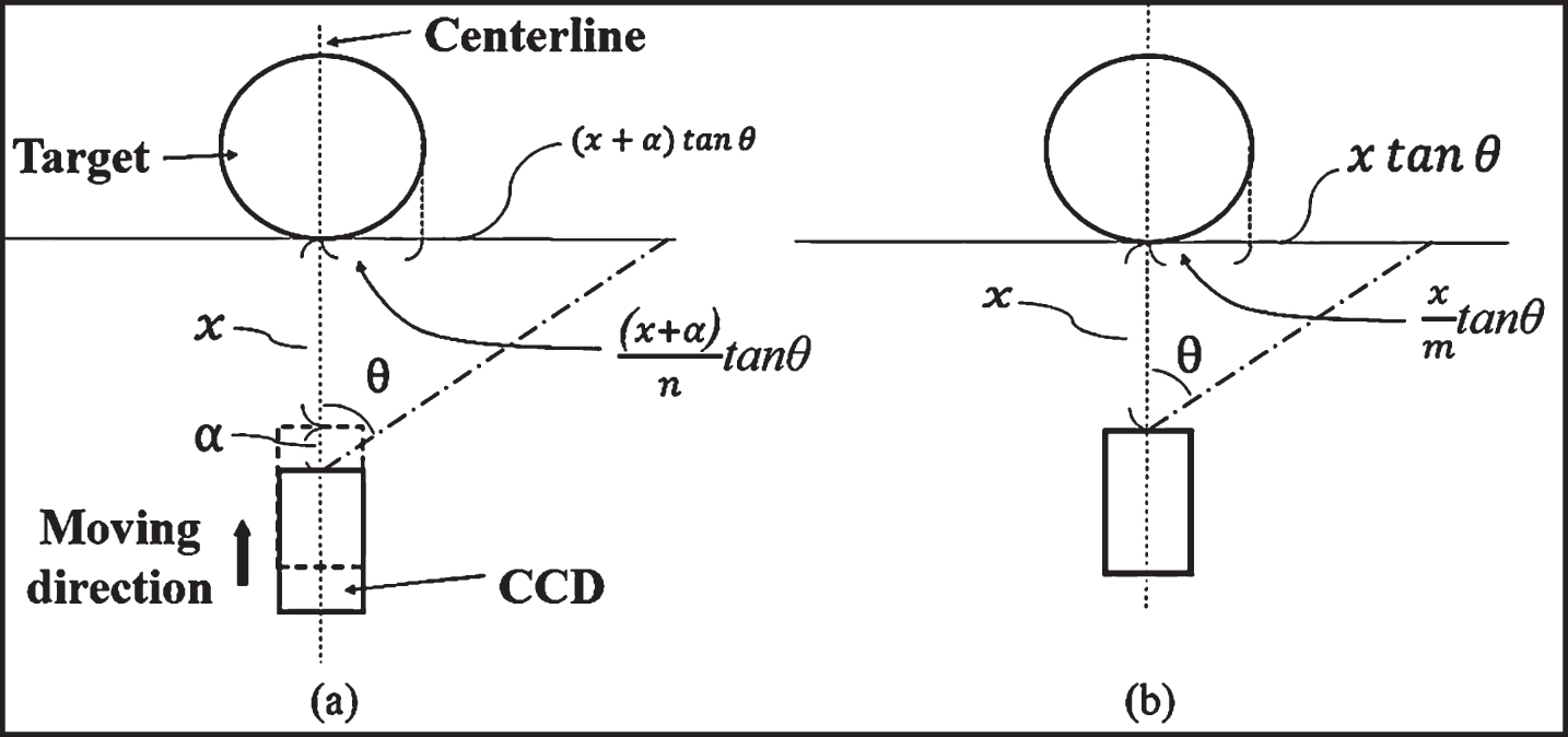
An illustration before (a) and after (b) the CCD moves forward to the target in the depth direction.
According to Equation (2), the 4-DOF robot arm with monocular vision is able to track and catch both static and moving targets in three-dimensional space once the CCD moves α forward to the target by obtaining the n and m ratios from image processing. In this study, the central position of the target image and the number of pixels are obtained by using color characteristics image processing as shown in Fig. 6. In Fig. 6(a) and (b), using image processing software based on an orange color filter, the numbers of pixels of the width of the FOV and the target images of 75 pixels and 125 pixels are obtained by the CCD measurement before and after the CCD moves the distance α of 5 cm, respectively. n of 2 and m of 1.2 are derived from Fig. 6(a) and (b). As a result, the distance x of 7.5 cm between the target and the CCD, and the central height position of the target of 3.1 cm from the gripper of 4-DOF robot arm are obtained from Fig. 6(c) by Equation (2). Therefore, this study converts this two-dimensional calculation to three-dimensional space using forward and inverse kinematics so the 4-DOF robot arm can position, grip, and carry a moving target.
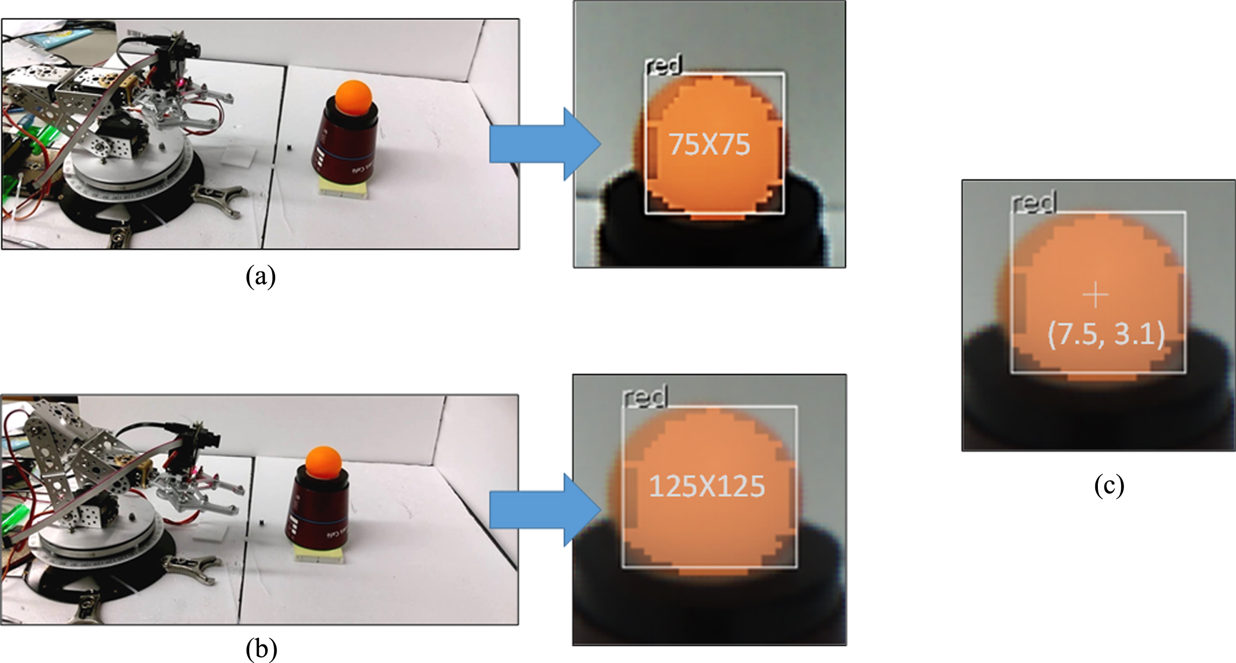
Photos and the numbers of pixels of the width of the FOV and the target images of 75 pixels and 125 pixels before (a) and after (b) the CCD moves the distance α of 5 cm, respectively. (c) A result of distance x of 7.5 cm between the target and the CCD, and the central height position of the target of 3.1 cm from the gripper of 4-DOF robot arm by color characteristics image processing.
In order to move the CCD to calculate the relative distance between the target and the robot arm, the coordinates of the 4-DOF robot arm are defined as shown in Fig. 7.
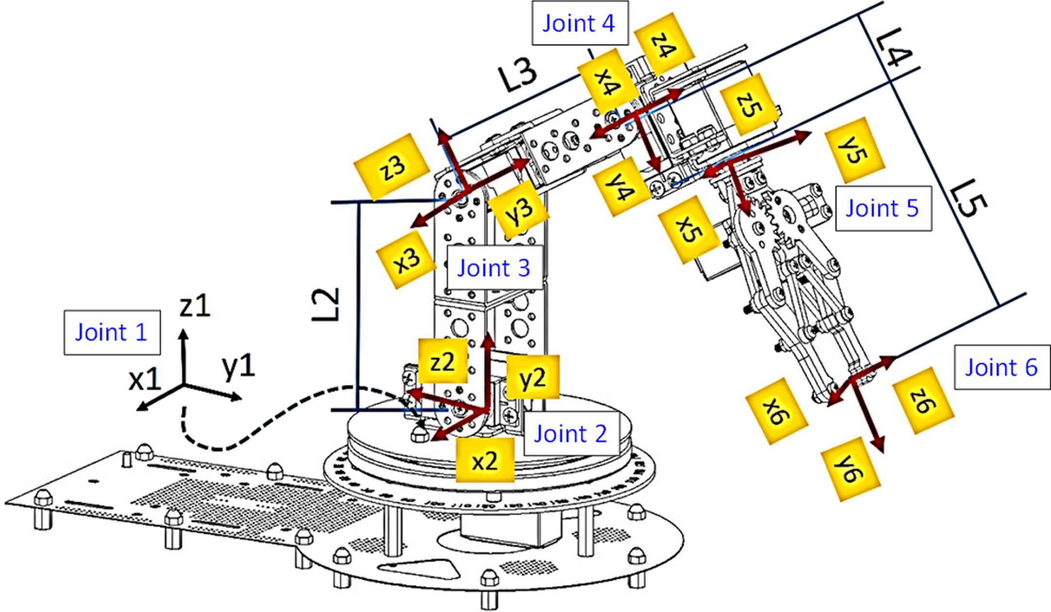
Coordinates of the 4-DOF robot arm.
Homogeneous transfer matrices are used for forward and inverse kinematics derivation. Forward kinematics calculates the position of the end effector (gripper) as shown from Equations (3 to 20). The forward kinematic parameters are given by the following variables: L1: Since the extension axis of the rotation (Joint 1) of the base servo motor does not pass the coordinate axis origin of Joint 2, there is a horizontal position difference, and its value is defined as L1. L2: The difference between the coordinate axes of Joints 3 and 2 in the Z-axis direction L3: The difference between the coordinate axes of Joints 4 and 3 in the Y-axis direction L4: The difference between the coordinate axes of Joints 5 and 4 in the Y-axis direction L5: The difference between the coordinate axes of Joints 6 and 5 in the Y-axis direction h1: The difference in height between the reference axes of Joints 2 and 1 in Z-axis direction h2: The difference in height between the coordinate axes of Joints 5 and Joint 4 in Z-axis direction θi: The rotation angle of each joint’s rotation axis; where i = 1, 2, 3, 4, and 5 si: Represents sin(θi); i = 1, 2, 3, 4, 5 ci: Represents cos(θi); i = 1, 2, 3, 4, 5
T12: Homogeneous transfer matrix between Joints 1 and 2
T23: Homogeneous transfer matrix between Joints 2 and 3
T34: Homogeneous transfer matrix between Joints 3 and 4
T45: Homogeneous transfer matrix between Joints 4 and 5
T56: Homogeneous transfer matrix between Joints 5 and 6
T16: Homogeneous transfer matrix between Joints 1 and 6
The elements in Equation (8) are given by Equations (9 through 20).
Inverse kinematics calculates the angle between each joint and the desired position of the end effector as shown from Equations (21 to 36).
In Equation (21),
According to Equations (21 and 22), θ1 is derived as
In Equation (21), the inverse kinematic parameters for the 4-DOF robot arm are given by
Equation (29) is obtained by squaring Equations (27 and 28) and multiplying the result together.
where
θ3 is derived as
Equations (27 and 28) are rewritten as
Solving Equation (31) gives
Substituting Equations (33) into (32) gives
where γ is L2+L3c3.
θ2 and θ4 are derived as
Dynamic modeling
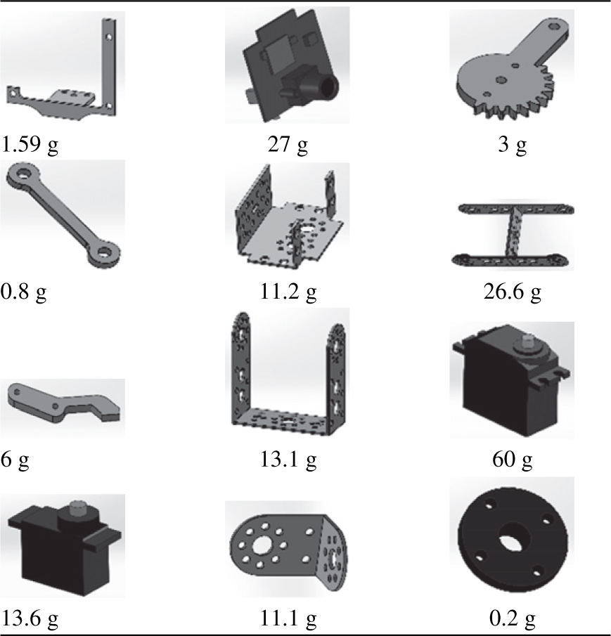
To simulate the forward and inverse kinematics of the 4-DOF robot arm, this study utilizes MATLAB Simulink and SimMechanics software. First, the 4-DOF robot arm is drawn in SolidWorks based on the mass characteristics of the components shown in Table 1. All the components of the 4-DOF robot arm then are assembled in SolidWorks and MATLAB SimMechanics exports the robot arm into MATLAB Simulink, as shown in Fig. 8. Moreover, MATLAB Simulink converts the dynamic model of the 4-DOF robot arm to a block diagram as shown in Fig. 8.
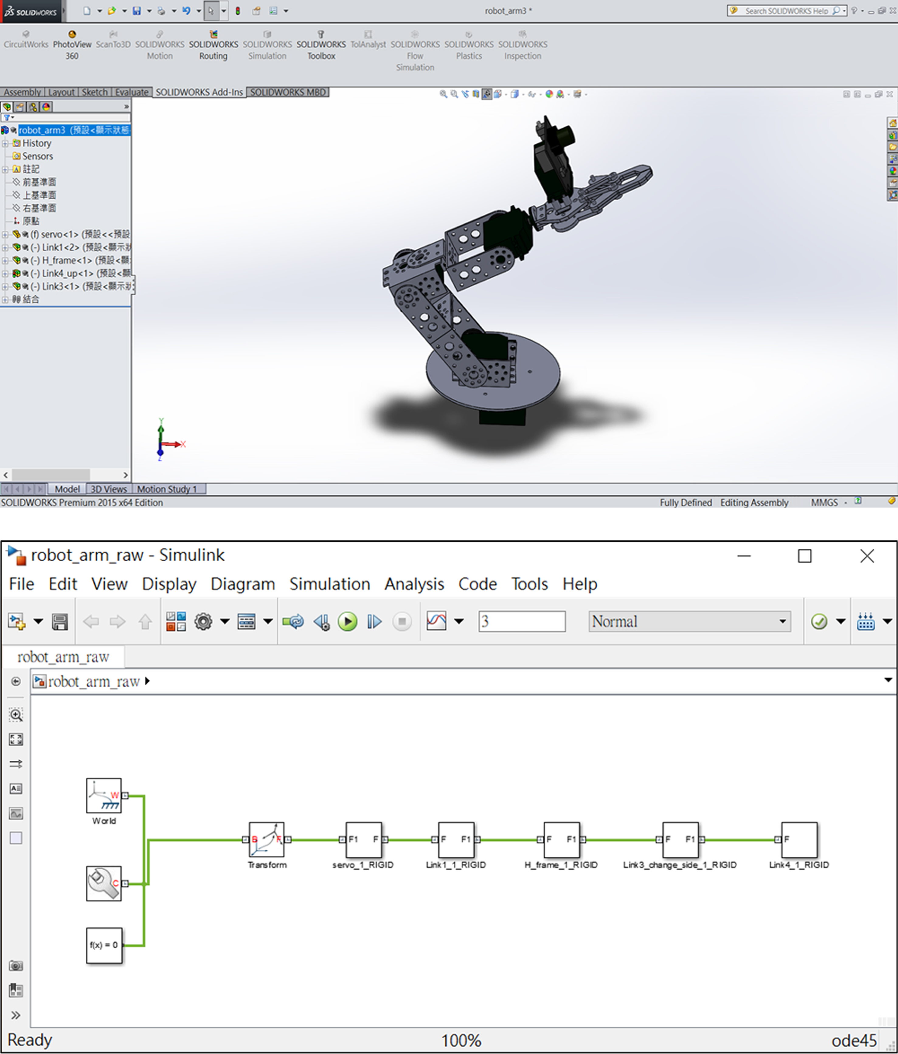
An export of the robot arm from (a) SolidWorks into (b) MATLAB Simulink using MATLAB SimMechanics.
Mass characteristics of the components of the 4-DOF robot arm
To grip a moving target, this study utilizes the two-dimensional vision sensing method to measure the dynamic position of the target using a single CCD on the 4-DOF robot arm. In the dynamic model in MATLAB SimMechanics, proportional–integral–derivative (PID) [8] controllers are used in Joints 1 to 4 as shown in Fig. 9. The proper PID parameters of each controller are tuned in MATLAB SimMechanics to the desired transient and steady responses as shown in Fig. 10 in order to increase the rate at which the 4-DOF robot arm can grip the target.
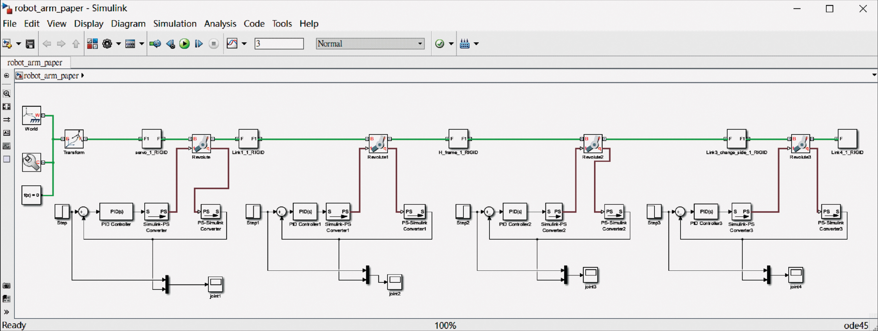
Design of PID controllers of Joints 1 to 4 by MATLAB SimMechanics.
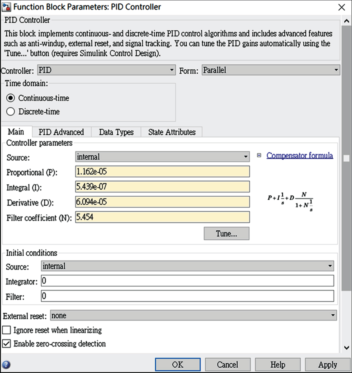
Tuning PID parameters of each controller.
To demonstrate a precise control of the point-contact grip, this study utilizes a ping pong ball as a target. A computer uses a PID controller and the two-dimensional vision sensing method calculations to command the Arduino Uno microcontroller to drive the robot arm to statically grip the ping pong ball.
In Fig. 11, the ping pong ball is at a distance of 100 mm from Joint 1 in both the negative x-axis and positive y-axis directions. Unfortunately, a vibration caused by one of servomotors in Joints 1 to 4 affects the position measurements of the target. Figure 12 depicts the response of the two-dimensional vision sensing method as the 4-DOF robot arm attempts to grip a static ping pong ball. The sampling time is 0.3 s due to the image processing software used by two-dimensional vision sensing method. The servomotors were driven at a too high speed, causing vibrations in the joints of the 4-DOF robot arm. Figure 12 illustrates delays at 0.3, 1.8, and 3.0 s to allow additional time for image processing due to the vibrations. Additionally, Fig. 12 shows the 4-DOF robot arm requires 5.7 s to grip the static ping pong ball using the two-dimensional vision sensing method.
To improve upon the response time, this study then utilizes a proportional controller in Joint 1 to stabilize the moving target in the central position of the field of view of the CCD. In this study, the proportional parameter of 3.87×10⁻⁶ is designed for the proportional controller by using MATLAB SimMechanics software. Moreover, this study adds a fuzzy controller to control Joints 1, 2, 3, and 4 to improve response time of grip operation. The control block diagram of the 4-DOF robot arm system based on this proportional-fuzzy controller is shown in Fig. 13.
According to literature [9], fuzzy control is the process of incorporating expert experience of a human operator into the process of controlling the input and output relationships by using a set of fuzzy control rules. This study utilizes fuzzy control to improve the driving of the servomotors at a too-high speed. The fuzzy-control architecture is comprised of four principal components: a fuzzification interface, a knowledge base, an inference engine, and defuzzification interface.
The knowledge base consists of fuzzy IF-THEN rules involving linguistic variables rather than a complex dynamic model. The inference engine is the core of the fuzzy control in modeling human decision making by combining IF-THEN rules and the knowledge base. In this study, Mamdani’s minimum fuzzy implication rule (MMFIR) method [9] is utilized. To improve the response time of grip operation and too high-speed driving of servomotors, this study uses the following nine fuzzy rules: R1: IF input distance is Imf1, then output distance is Omf1. R2: IF input distance is Imf2, then output distance is Omf2. R3: IF input distance is Imf3, then output distance is Omf3. R4: IF input distance is Imf4, then output distance is Omf4. R5: IF input distance is Imf5, then output distance is Omf5. R6: IF input distance is Imf6, then output distance is Omf6. R7: IF input distance is Imf7, then output distance is Omf7. R8: IF input distance is Imf8, then output distance is Omf8. R9: IF input distance is Imf9, then output distance is Omf9.
The core of the fuzzification interface is the design of the membership function, which has the effect of transforming clear measurement data into appropriate linguistic values. In this study, a triangular membership function [9] is utilized. The input membership function is designed to be uniformly distributed in a trigonometric feature based on nine fuzzy rules within a distance of 300 mm. The output membership function is designed to be non-uniformly distributed in a trigonometric feature within a distance of 70 mm to regulate the speed driving stability of the servomotors for the improvement of the response time of grip operation. Figure 14(a) and (b) depict the design of input and output membership functions.

Static grip operation of ping pong ball by 4-DOF robot arm system.
The defuzzification interface maps the fuzzy control behavior space of the output domain onto a crisp control behavior space. This study utilizes a center of area (COA) method [9] for the defuzzification, which generates the center of gravity of the distribution of control action possibilities. In the case of a discrete universe, the COA method is expressed as Equation 37:
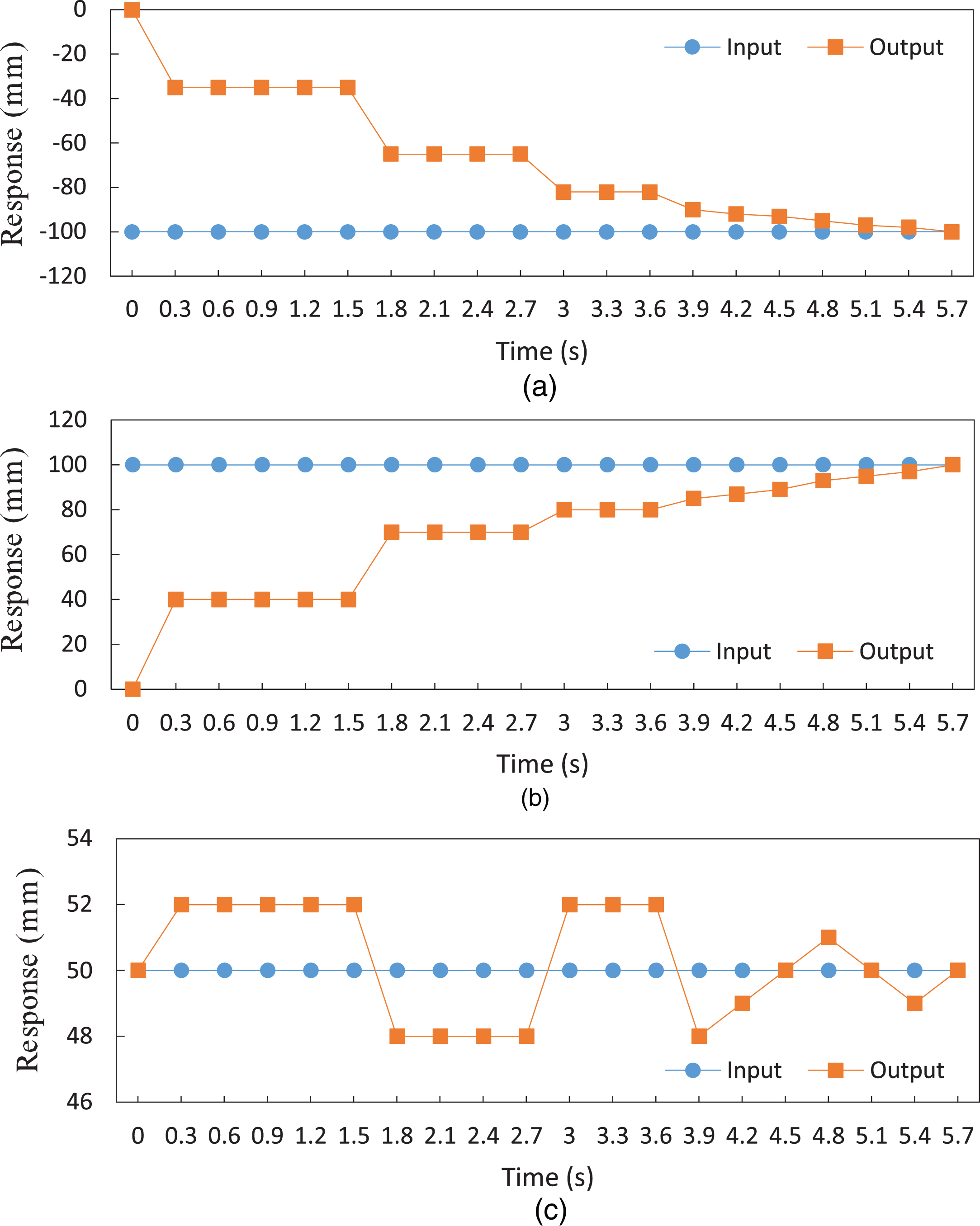
(a) x-axis, (b) y-axis, and (c) z-axis position of the 4-DOF robot arm during grip operation using PID control.

Control block diagram of 4-DOF robot arm system based on the proportional-fuzzy controller.
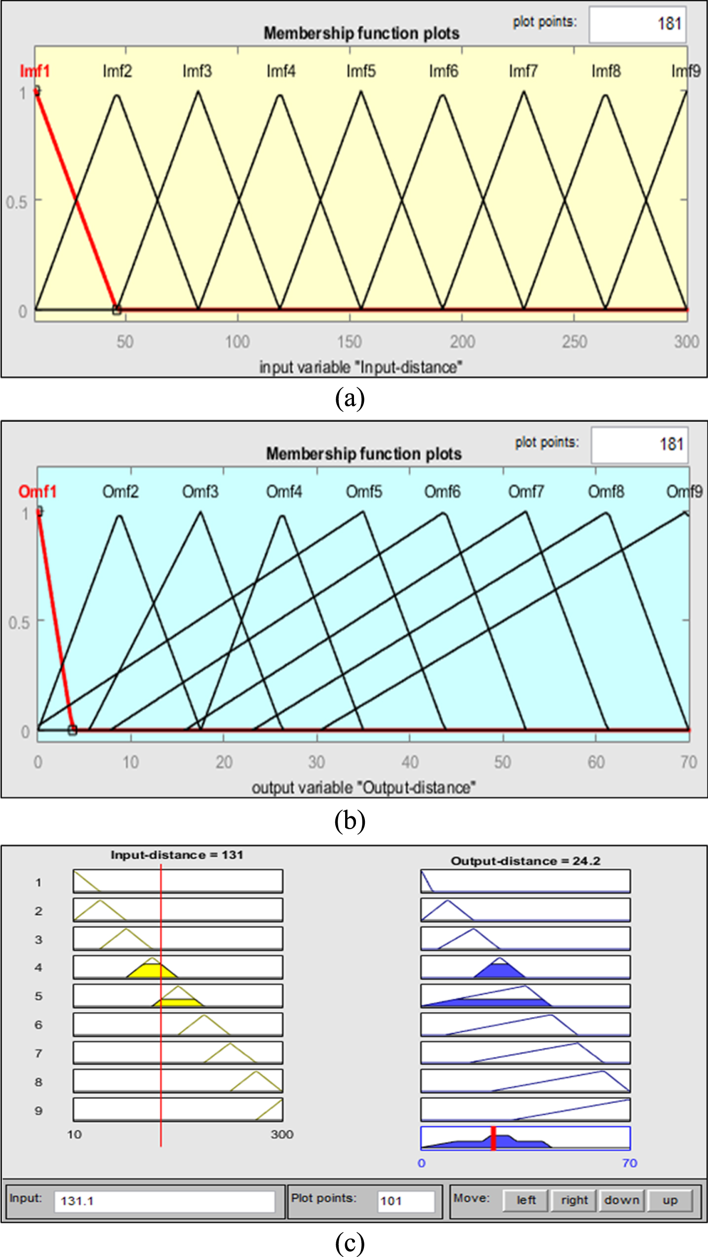
Design of (a) input and (b) output membership functions based on (c) the defuzzification of COA method.
where n is the number of quantization levels of the output, O j is the amount of control output at the quantization level j, and μ O (O j ) represents its membership degree in the output fuzzy set O. Figure 14(c) shows a case where the fuzzy-controller output distance of 24.2 mm is obtained from an input distance of 131 mm calculated from these input and output membership functions based on the COA defuzzification method.
The performance of a static grip operation using proportional-fuzzy control of the 4-DOF robot arm is shown in Fig. 15. The sampling time of the 4-DOF robot arm is again 0.3 s due to the image processing of the two-dimensional vision sensing method. In Fig. 15, there is not any time delay due to vibrations of the joints. In the first 2.1 s, the 4-DOF robot arm approaches the static ping pong ball at a constant speed of 35 mm/s in x-axis and y-axis directions. The 4-DOF robot arm based on proportional-fuzzy control requires 4.5 s to grip the static ping pong ball. The response time and stability using proportional-fuzzy controller is better than a PID controller.
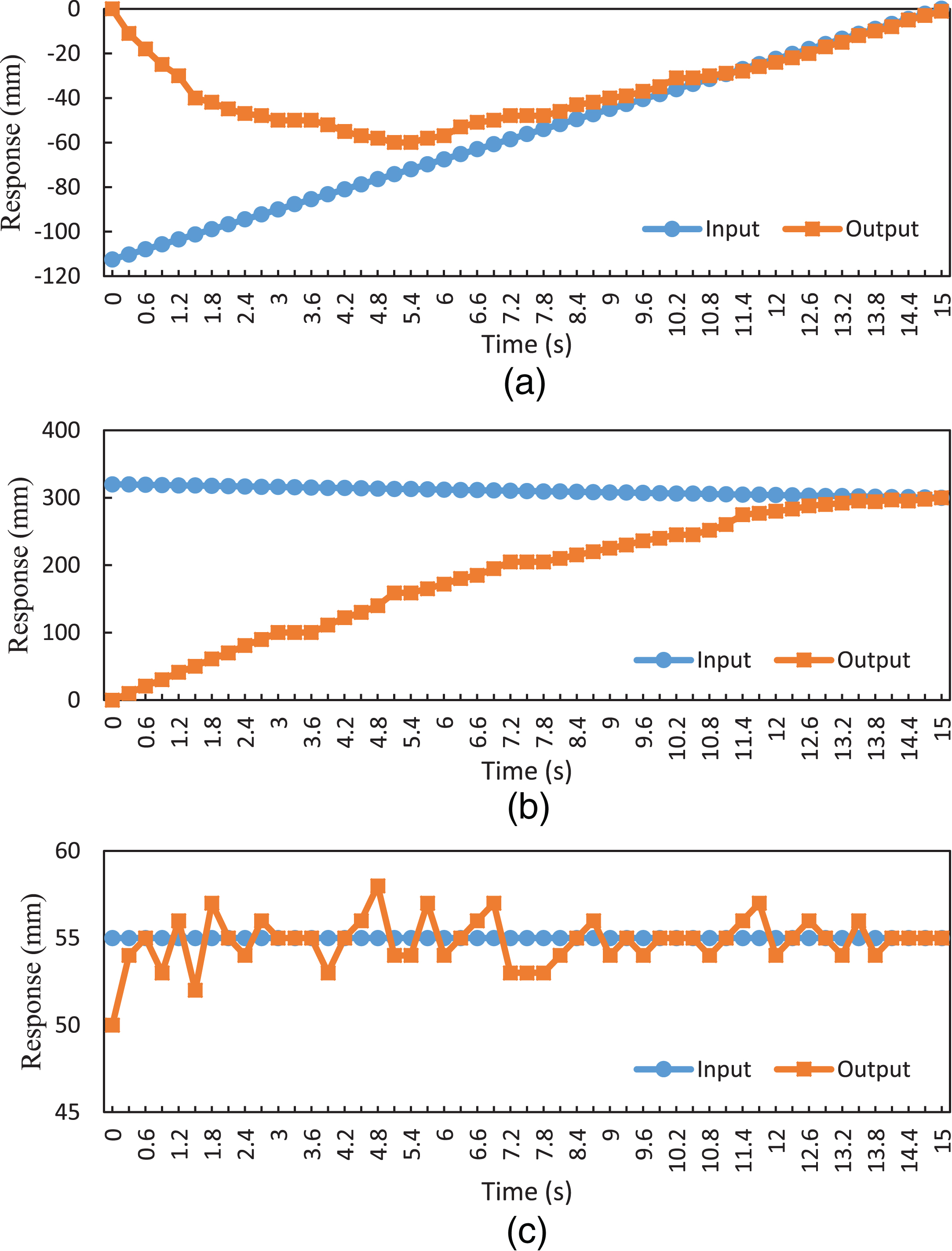
(a) x-axis, (b) y-axis, and (c) z-axis position of the 4-DOF robot arm during static grip operation using proportional-fuzzy control.
To grip a target on a moving stage, this study utilizes a laser distance sensor. The moving platform moves a ping pong ball at a constant speed of 7.5 mm/s in negative and positive x-axis directions as shown in Fig. 16.
Figure 17 depicts seven steps in the grip operation of the ping pong ball. This illustrates that the 4-DOF robot arm can successfully position, grip, and carry a moving ping pong ball to a designated place in three-dimensional space using proportional-fuzzy control and the two-dimensional vision sensing method Fig. 18 shows the performance of the grip operation. At 3.0, 5.1, 7.2, and 10.2 s, the image processing requires more time to obtain the positions of the moving ping pong ball. Although the 4-DOF robot arm requires 15 s to grip the ping pong ball using this method, by requiring only one CCD, the weight and cost of a 4-DOF robot arm can be reduced.
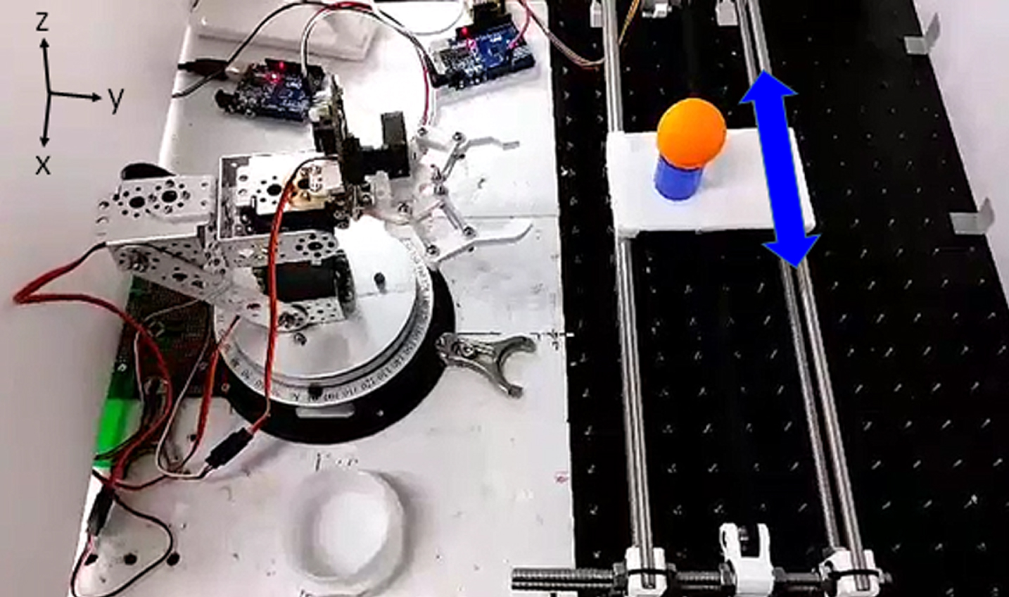
Moving platform for grip operation of moving target.
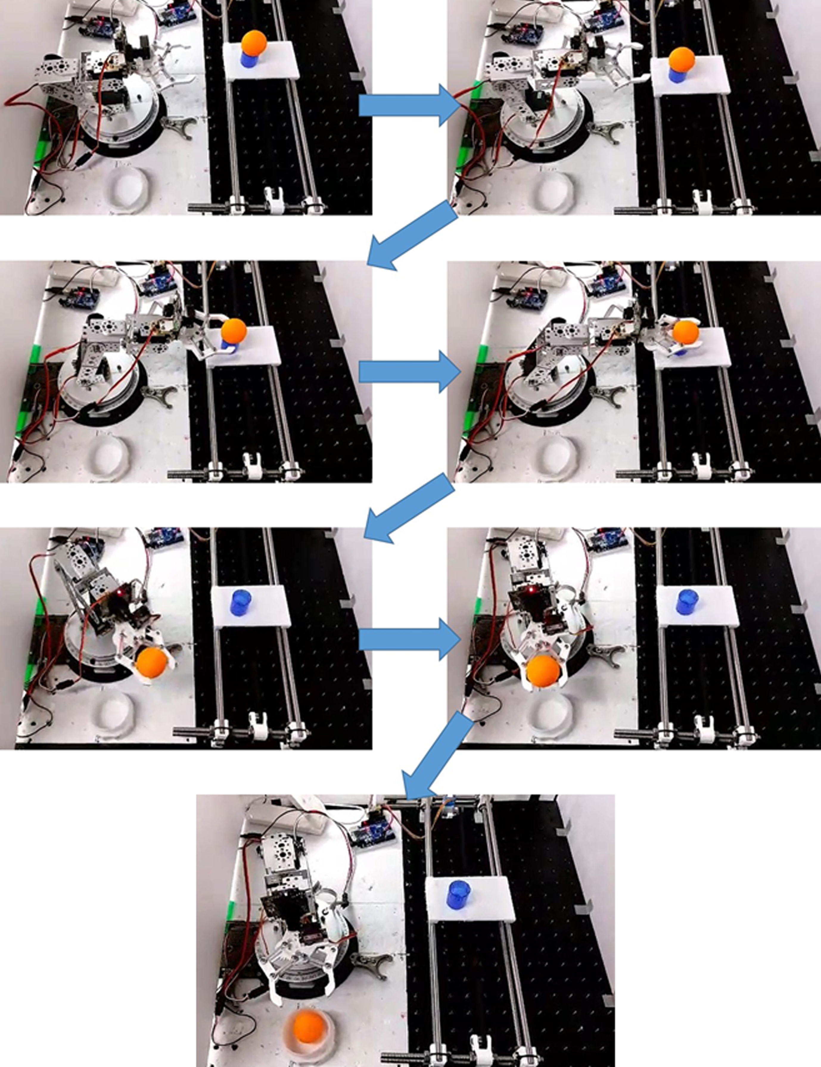
Seven photos of a ping pong ball on the moving platform, in order during grip operation.
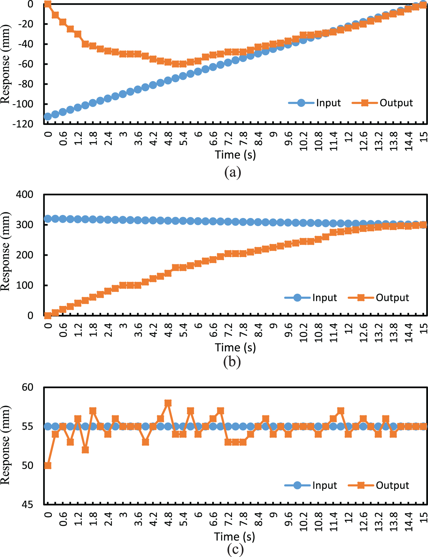
(a) x-axis, (b) y-axis, and (c) z-axis axis position of the 4-DOF robot arm during moving grip operation using proportional-fuzzy control.
This study has presented a 4-DOF robot arm successfully gripping a ping pong ball on a moving platform by using proportional-fuzzy control and the two-dimensional vision sensing method. This study has utilized forward and inverse kinematics to establish a dynamic model of a 4-DOF robot arm in MATLAB SimMechanics software to convert a single CCD’s two-dimensional vision to three-dimensional space. According to simulation results of transient and steady states, the response performance based on dynamic proportional-fuzzy controller is better than a PID controller’s response. Using dynamic proportional-fuzzy grip control and the two-dimensional vision sensing method, a 4-DOF robot arm can position, grip, and carry a moving ping pong ball to a designated place in three-dimensional space using only one CCD. This result breaks through the previous limitation of two-dimensions for of a single CCD. Using only one CCD can reduce the weight and cost of a 4-DOF robot arm to complete the grip operation of moving target. The success of this study demonstrates this technology, to grip moving targets on a moving platform, and to reduce future manpower and cost for industries such as manufacturing or agriculture.