
Abstract
In this study an adaptive on-line speed estimation approach has been proposed for a sensor-less indirect air-gap field orientation controlled (AGFOC) induction motor (IM) drive. The indirect AGFOC IM drive was established by utilizing the stator current and air-gap flux. The estimated synchronous speed was derived from the developed reactive power based adaptive air-gap flux estimator, and the estimation of rotor speed was made by subtracting the slip speed from the estimated synchronous speed. Speed estimation and control by the AGFOC IM drive could be extended to include constant power operation mode by utilizing the field weakening technique. The MATLAB® ∖Simulink ® toolbox was used to simulate this system and all the control algorithms were realized using a TI DSP 6713-and-F2812 card to generate pulse width modulation (PWM) signals to the power stage, actuate an IM to validate this approach (sensor-less AGFOC). Both simulation and experimental responses confirmed the effectiveness of the proposed system.
Keywords
Introduction
Modern advanced automatic facilities demand versatile electric drives. Induction motors are reliable, robust, have low maintenance requirements, and with their drive controls are relatively popular. High performance IM electric drive is now has a performance comparable to that of a DC motor drive. According to the field orientation control (FOC) theory for IM drives [1], utilization the coordinate transformation, the nonlinear coupling, and the time variant mathematical model of an IM can be regarded as having both torque and field current components. These components are orthogonal and independent, and the maximum torque / current ratio can be attained. However, the FOC approach requires the presence of a digital shaft position encoder to detect rotor speed and this makes the system less robust and unsuitable for a hostile environment [2]. FOC IM drives that use flux and rotor speed estimation are more useful and they are now extensively applied [3–6].
The FOC approach to IM drive control is classified into the rotor, stator, and air-gap. Most published studies about FOC IM drives have been focused on the stator and rotor [7–10], air-gap FOC has received less attention. Furthermore, an FOC IM drive can be categorized of the direct and indirect type. In the direct FOC type, the magnitude and position of the flux is directly estimated by utilizing the motor electric parameters such as the current and voltage. In the indirect FOC type, the flux positon is acquired from computing the rotor position and estimation slip angle.
Conventional variable speed control mode may be based on constant torque and constant power. The difference between these modes is the available operation speed region. In the constant torque operation mode, output power is proportional to the motor speed and depends on the rated set flux value, which is valid from standup to base speed. In the constant power operation mode (above base speed to two times base speed), the maximum available torque and the setting flux value are decreased with an increase in speed.
In this paper, indirect AGFOC IM drive was established by utilizing the stator current and air-gap flux, and the adaptive air-gap flux estimator was designed based on the reactive power of the IM, the estimated synchronous speed was derived from the developed adaptive air-gap flux estimation. The estimated rotor speed was acquired by subtracting the slip speed from the estimated synchronous speed. The proposed sensor-less AGFOC IM drive system was evaluated by simulation and implementation at different operation speeds.
Indirect air-gap field orientation controlled induction motor drive
The stator and rotor voltage vector equations of an IM at the synchronous reference coordinate frame are given by [11]
Under the AGFOC condition, set
Inspection of Equation (7), shows the q-axis stator current-coupling exists in the second term of the right side, by defining the feedforward compensation as
The simple relation between the estimation d-axis air-gap flux and the d-axis stator current can then be given by
The electromagnetic torque of an IM developed under an AGFOC condition is given by
Owing to
Also set
Inspection of Equations (11 and 12), allows definition of d- and q- axis voltage feedforward compensation as
And the linear control of the d- and q- axis stator current control loops can be attained. The voltage commands of the d- and q- axis stator current control loops are acquired respectively as
The real and imaginary parts of Equation (1) are given by
The reactive power of the IM is acquired from the power source and can be expressed as
Substituting Equations (17 and 18) into Equation (19), allows the absorbed reactive power of the IM to be expressed as
Under AGFOC condition (
According to the model reference adaptive system (MRAS) theorem [12], and owing to Equation (19) not containing the estimated synchronous speed
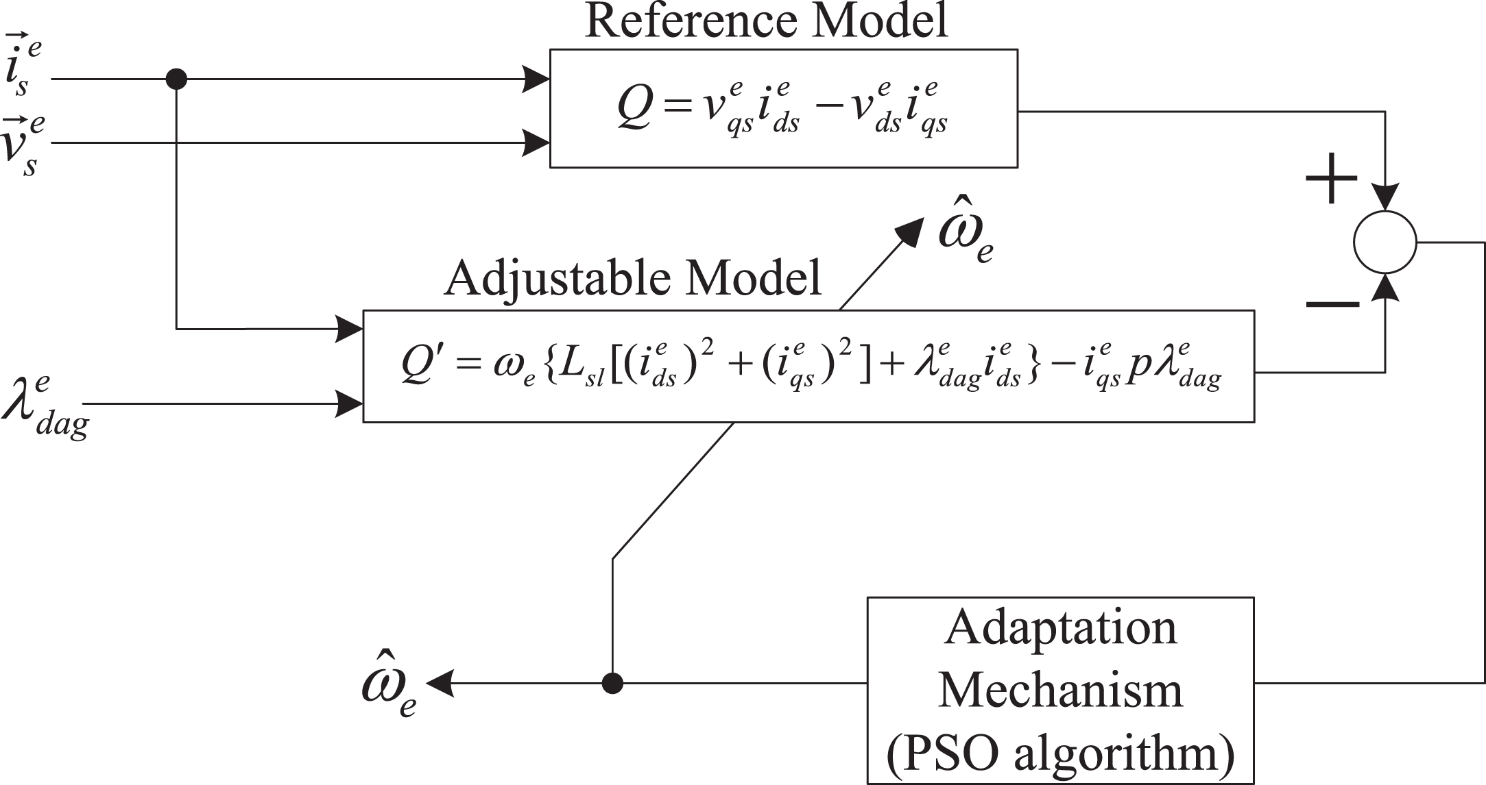
MRAS synchronous speed identification scheme based on the reactive power.
An estimation of the rotor speed under AGFOC conditions is acquired as
PSO algorithm adaptation mechanism design
The PSO algorithm is one of the optimum control methods, which has the advantages of demanding less adjustment parameters and rapid convergence [13]. Owing to conventional PSO algorithm causing the local solution rapid convergence, the inertia weighting PSO algorithm was adopted to design the adaptation mechanism of the MRAS synchronous speed identification scheme. The inertia weighting PSO algorithm is capable of searching optimum solution rapidly in the initial procedure and achieving effective convergence for the subsequent procedure [14]. The iteration formulas for velocity and position of the inertia weighting PSO algorithm is expressed as
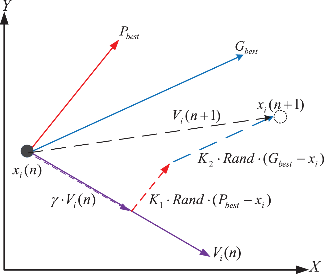
2-dimension searching of velocity and position of the particles.
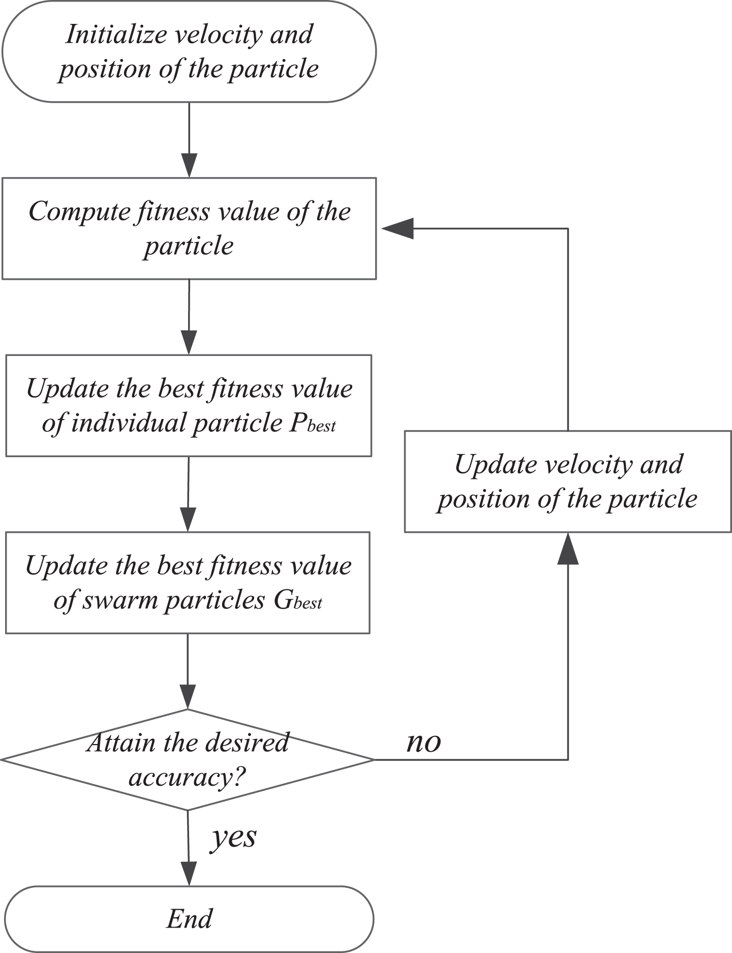
Flow chart of the inertia weighting PSO algorithm.
A block diagram of the proposed adaptive speed estimation indirect AGFOC IM drive is shown in Fig. 4, which includes the speed controller, flux controller, d-axis and q-axis stator current controller, air-gap flux setting value calculation, d-axis air-gap flux estimation, slip speed estimation, d-axis stator current feed-forward compensation, coordinate transformation, d-axis and q-axis voltage feed-forward compensation, and reactive power based MRAS synchronous speed identification.
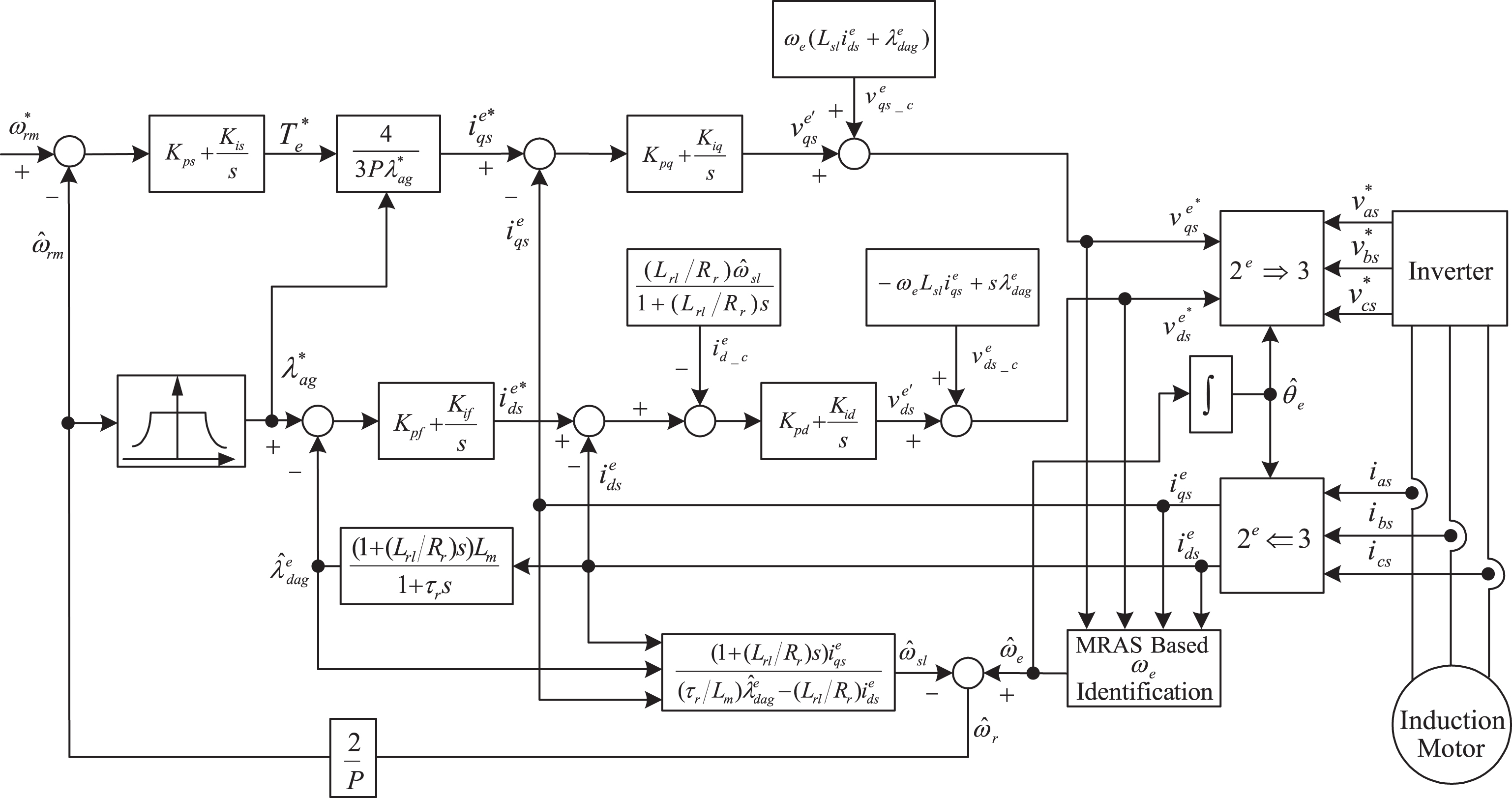
MRAS synchronous speed identification and speed estimation for the indirect AGFOC IM drive.
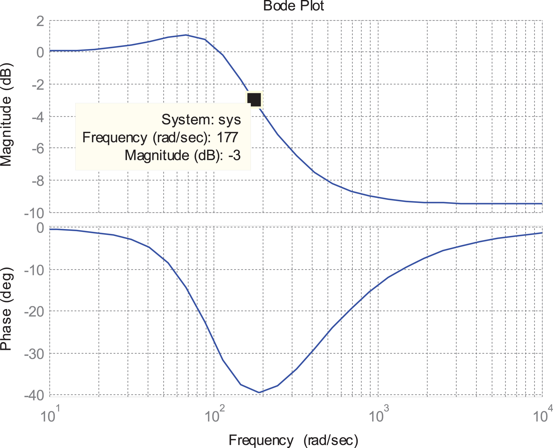
The proportion-integral (PI) type controllers for the speed control loop, flux control loop, d-axis and q-axis stator-current control loops are designed using the root-locus method, because of the transfer function of these control loops are the second order system [11], the damping ratio for design the controller was selected as about 0.707. The proportion gain (K p ), integral gain (K i ), and bandwidth (B. W) for the four PI type controllers are shown in Table 1, the root locus and Bode plot of the designed speed control loop, flux control loop, d-axis and q-axis stator current control loops are shown in Figs. 5–12, respectively.
Controller parameters and its bandwidth
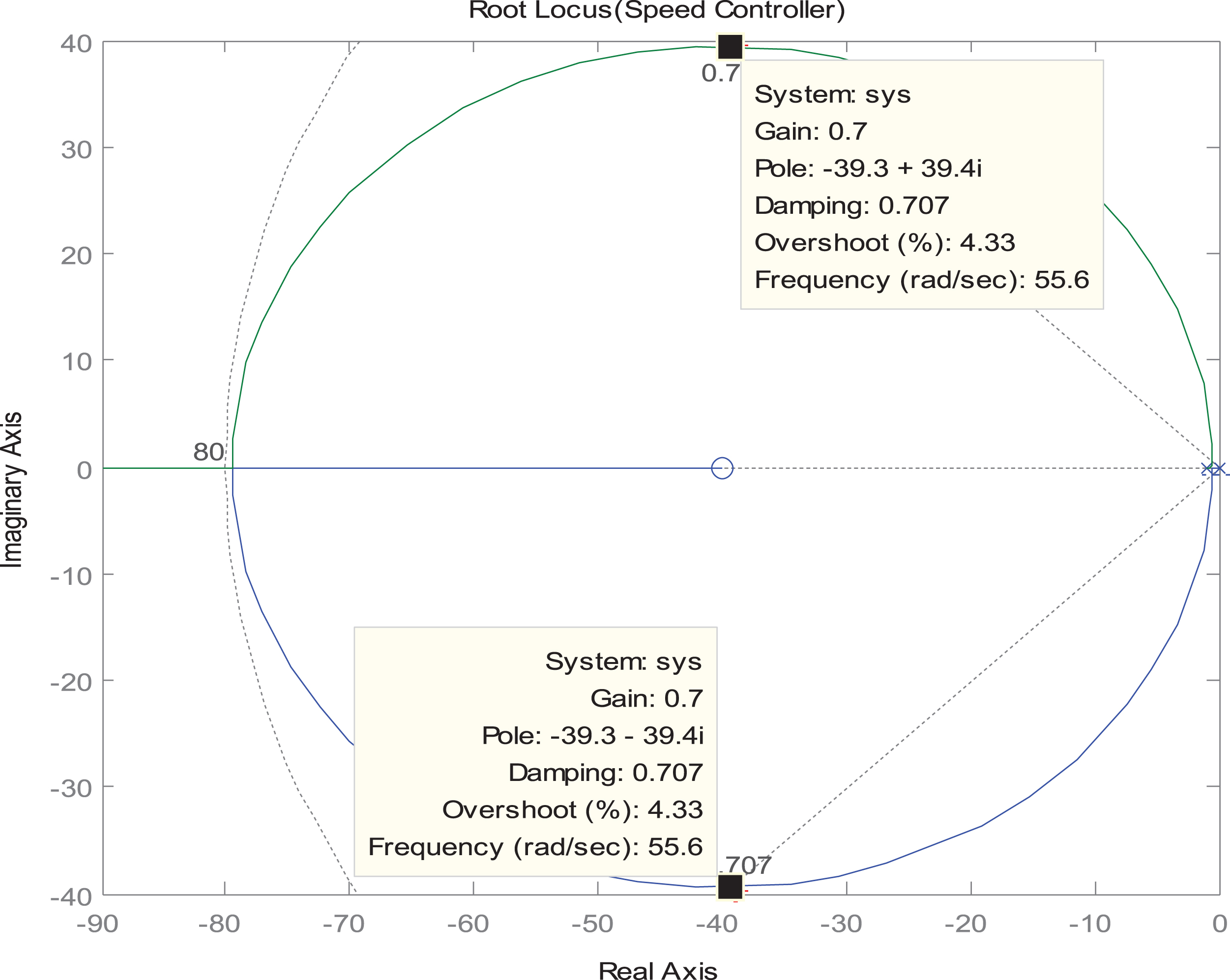
Root locus of the speed controller.

Bode plot of the speed controller.
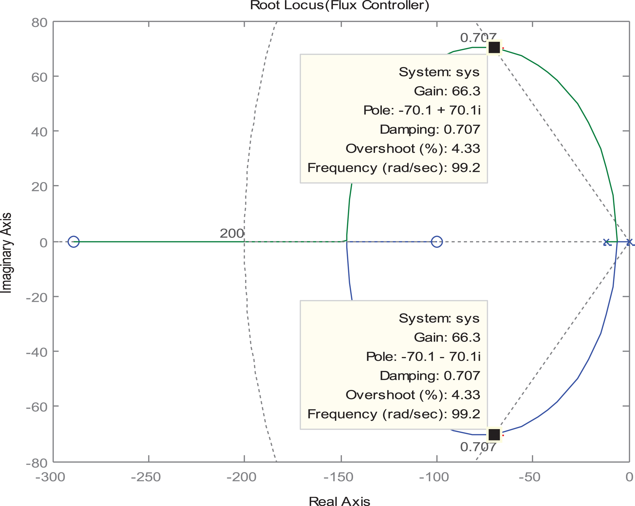
Root locus of the flux controller.
Bode plot of the flux controller.
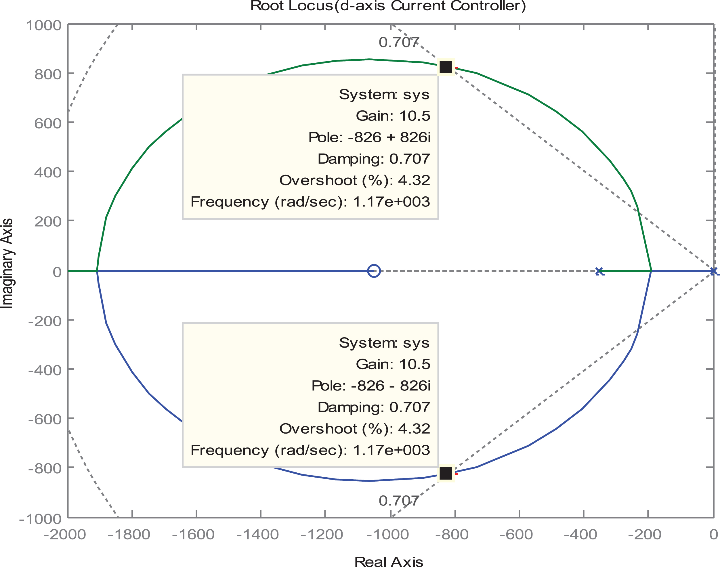
Root locus of the d-axis stator current controller.
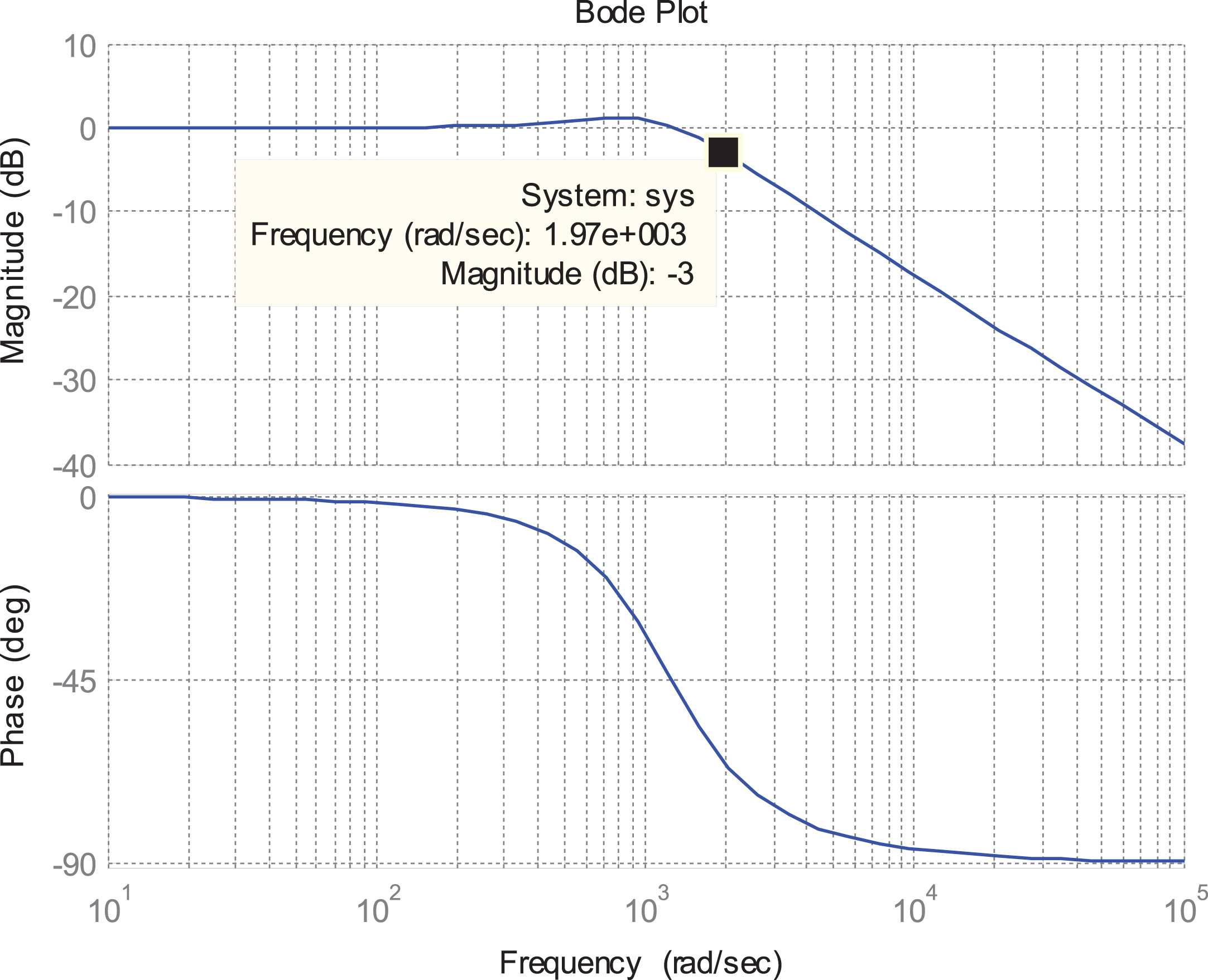
Bode plot of the d-axis stator current controller.
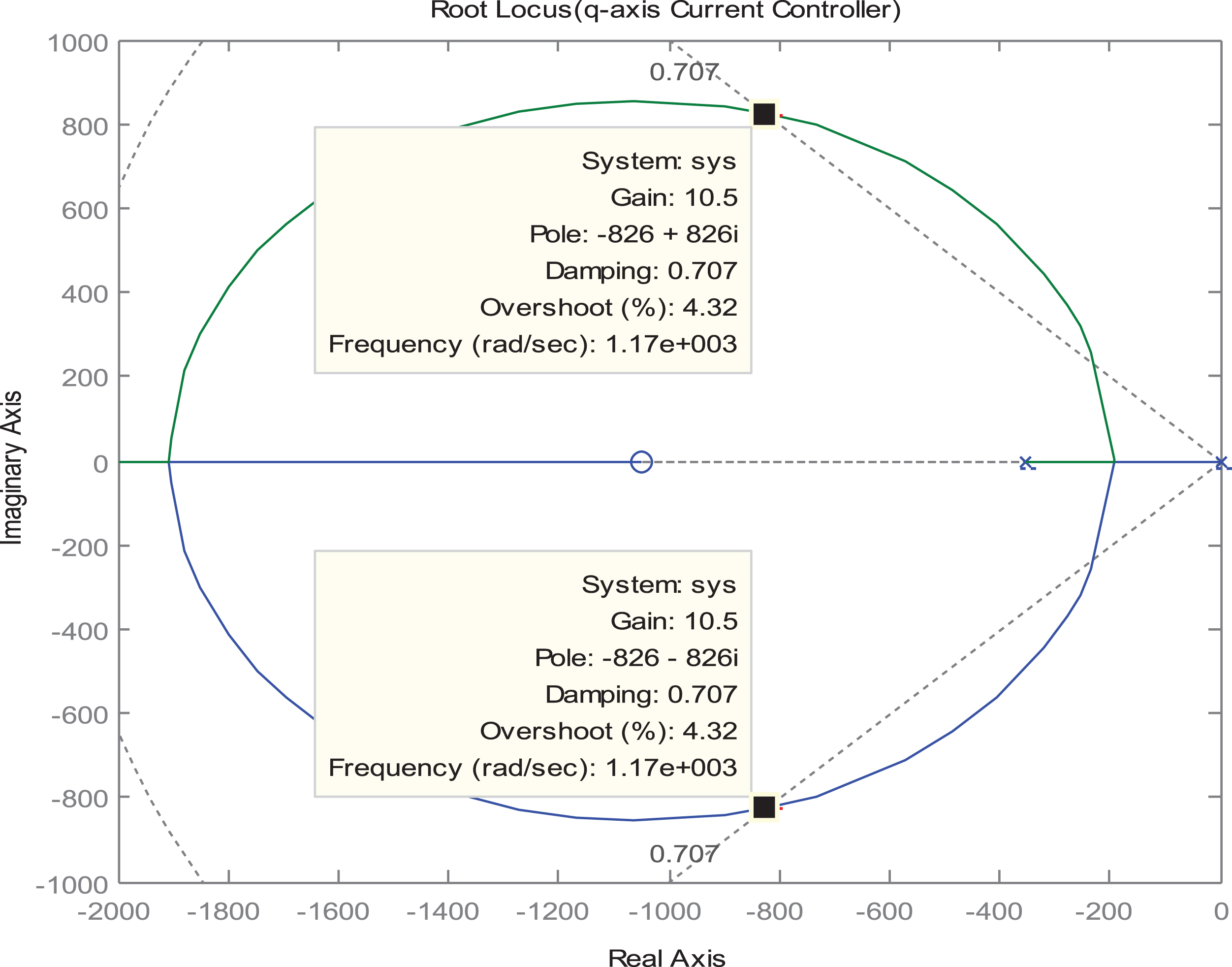
Root locus of the q-axis stator current controller.
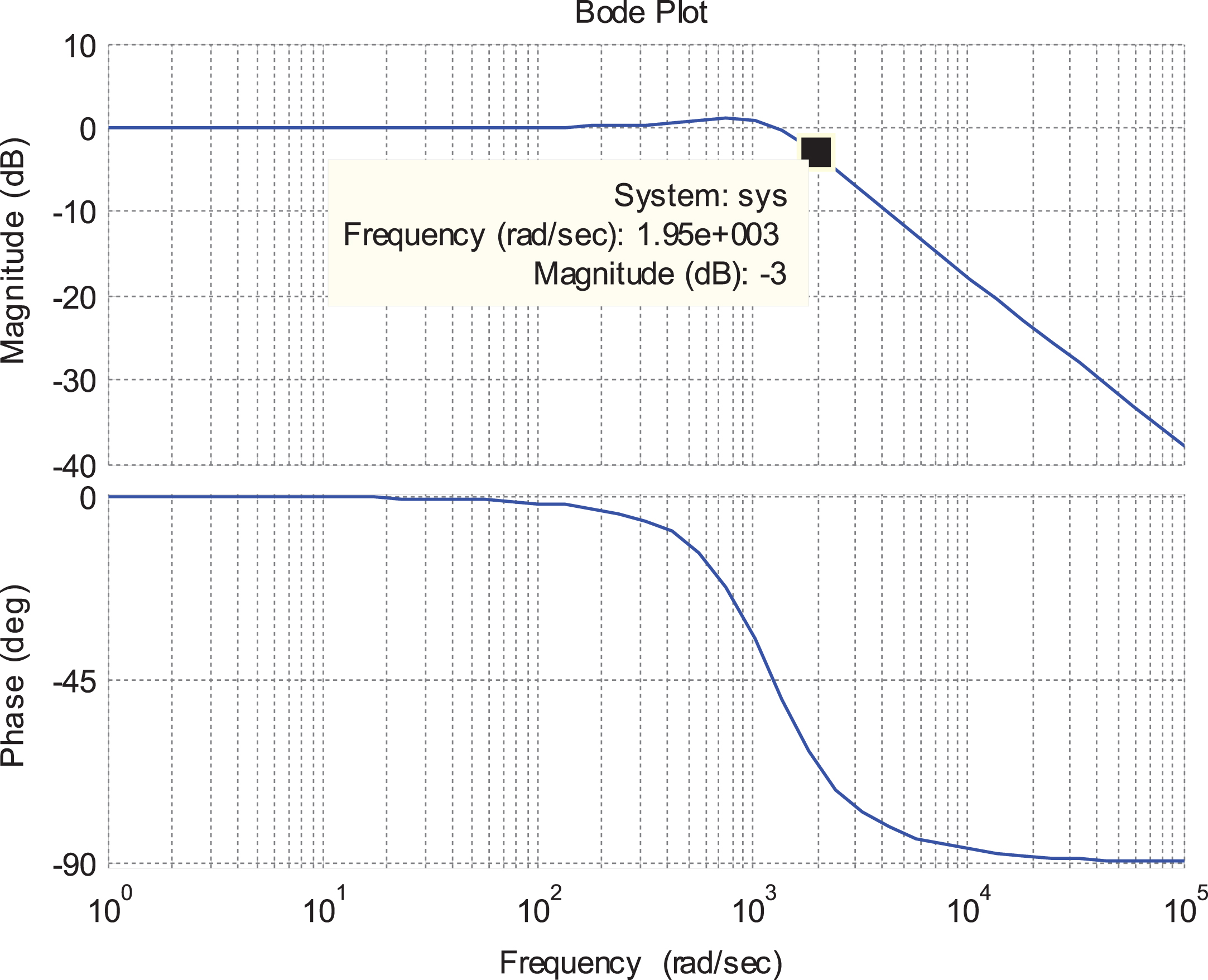
Bode plot of the q-axis stator current controller.
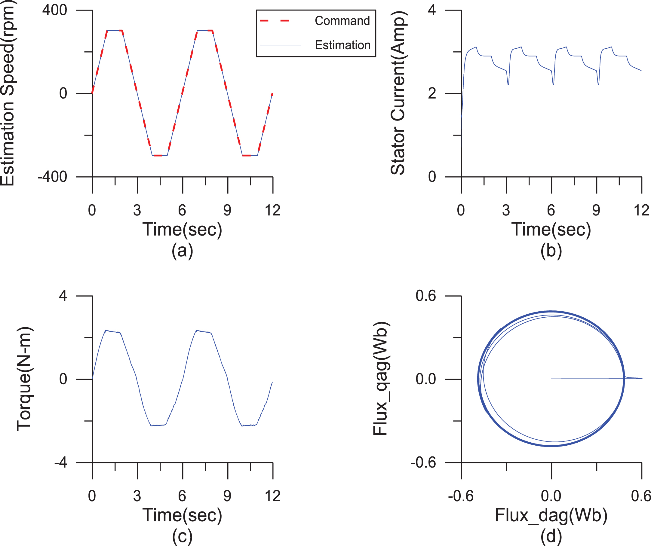
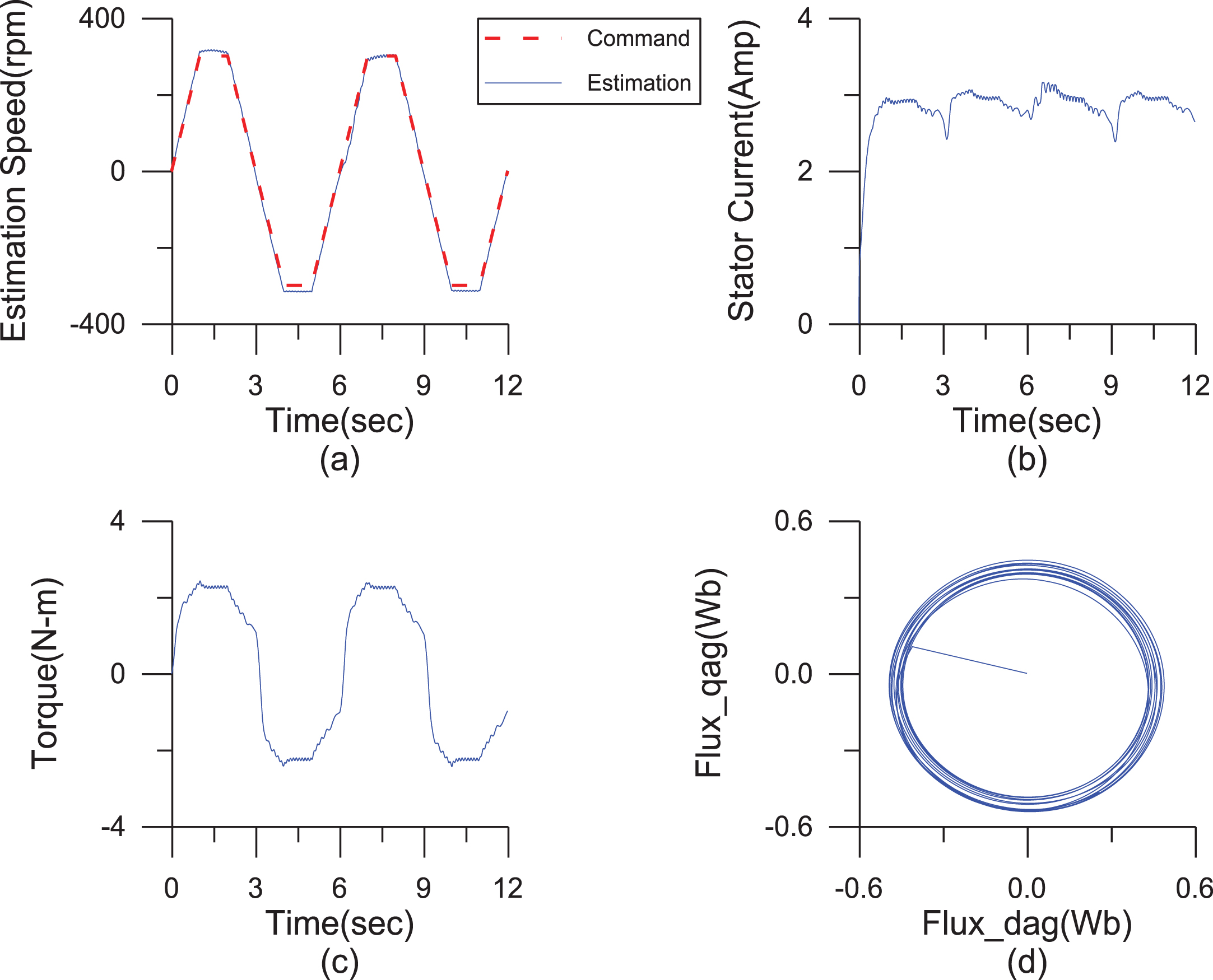
Simulated responses of the indirect AGFOC IM drive with loading 2 N-m at steady speed±300 rpm. (a)command (dotted line) and estimated (solid line) rotor speed, (b)stator current, (c)electromagnetic torque, (d)air-gap flux locus (q-axis air-flux V.S. d-axis air-flux).
Measured responses of the indirect AGFOC IM drive with loading 2 N-m at steady speed ±300 rpm. (a)command (dotted line) and estimated (solid line) rotor speed, (b)stator current, (c)electromagnetic torque, (d)air-gap flux locus (q-axis air-flux V.S. d-axis air-flux).
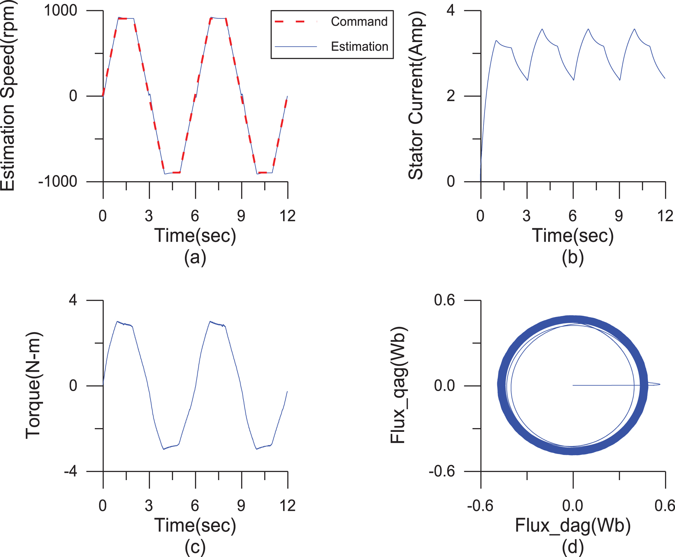
Simulated responses of the indirect AGFOC IM drive with loading 2 N-m at steady speed ±900 rpm. (a)command (dotted line) and estimated (solid line) rotor speed, (b)stator current, (c)electromagnetic torque, (d)air-gap flux locus (q-axis air-flux V.S. d-axis air-flux).
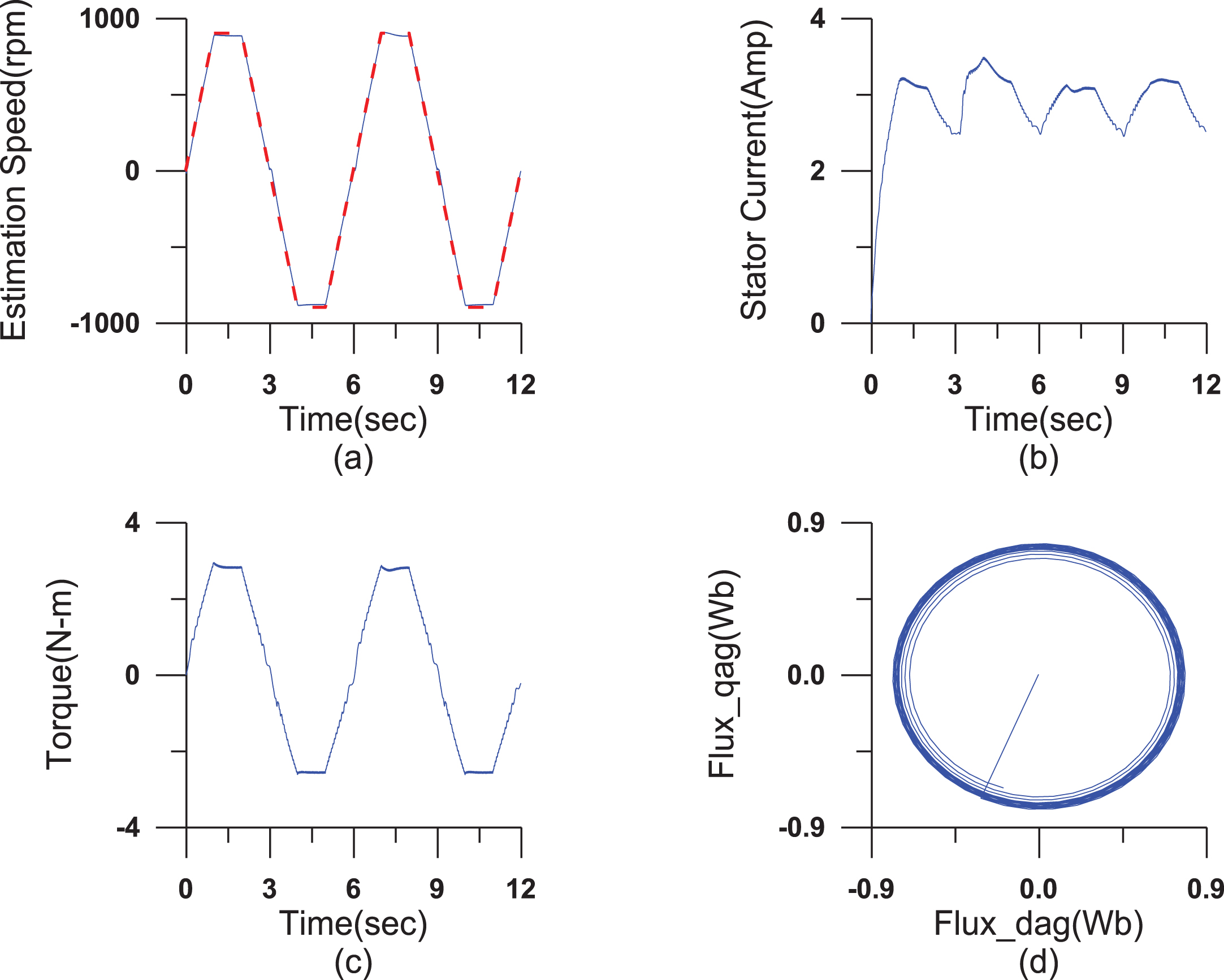
Measured responses of the indirect AGFOC IM drive with loading 2 N-m at steady speed ±900 rpm. (a)command (dotted line) and estimated (solid line) rotor speed, (b)stator current, (c)electromagnetic torque, (d)air-gap flux locus (q-axis air-flux V.S. d-axis air-flux).
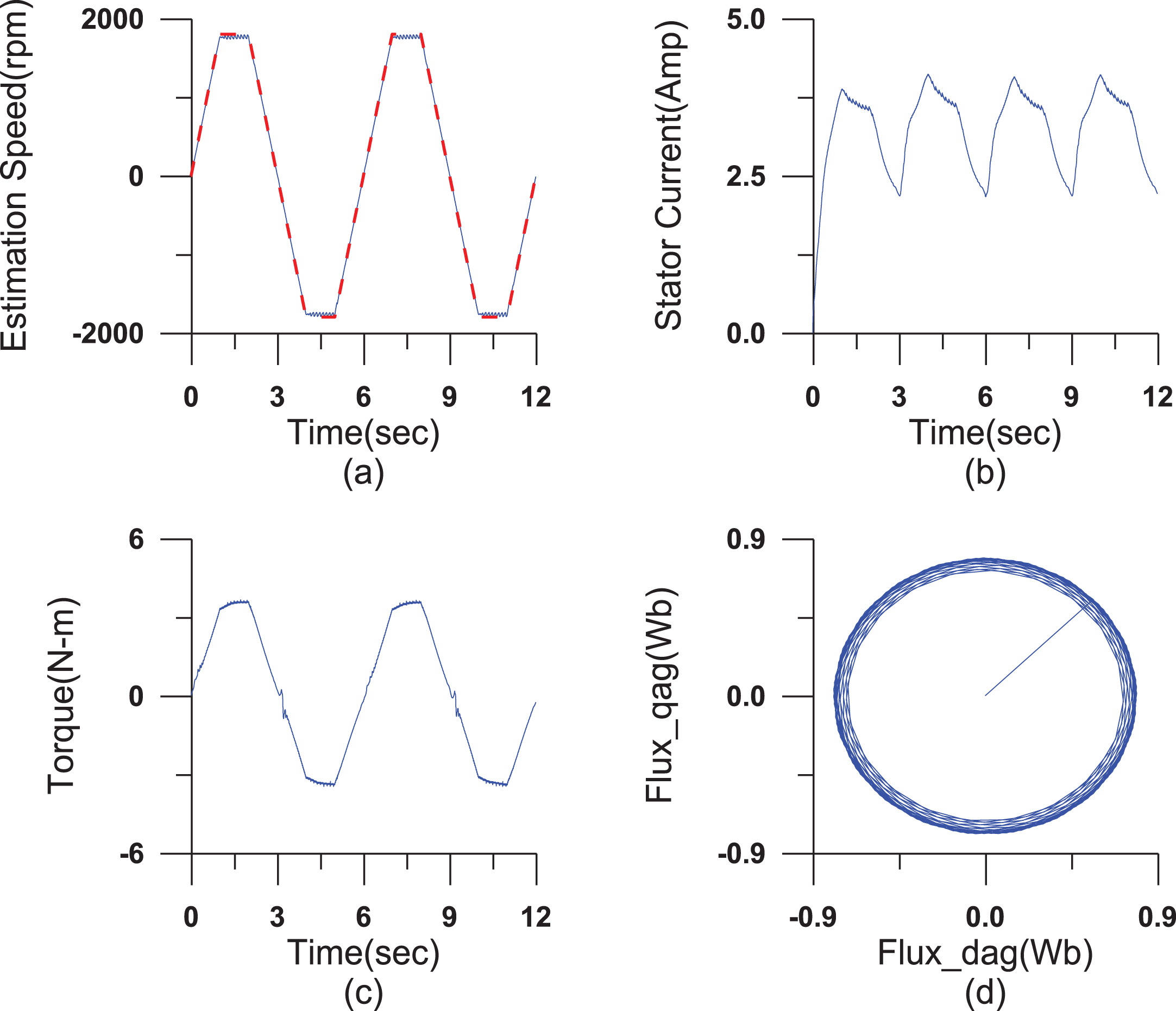
Simulated responses of the indirect AGFOC IM drive with loading 2 N-m at steady speed ±1800 rpm. (a)command (dotted line) and estimated (solid line) rotor speed, (b)stator current, (c)electromagnetic torque, (d)air-gap flux locus (q-axis air-flux V.S. d-axis air-flux).
Measured responses of the indirect AGFOC IM drive with loading 2 N-m at steady speed ±1800 rpm. (a)command (dotted line) and estimated (solid line) rotor speed, (b)stator current, (c)electromagnetic torque, (d)air-gap flux locus (q-axis air-flux V.S. d-axis air-flux).
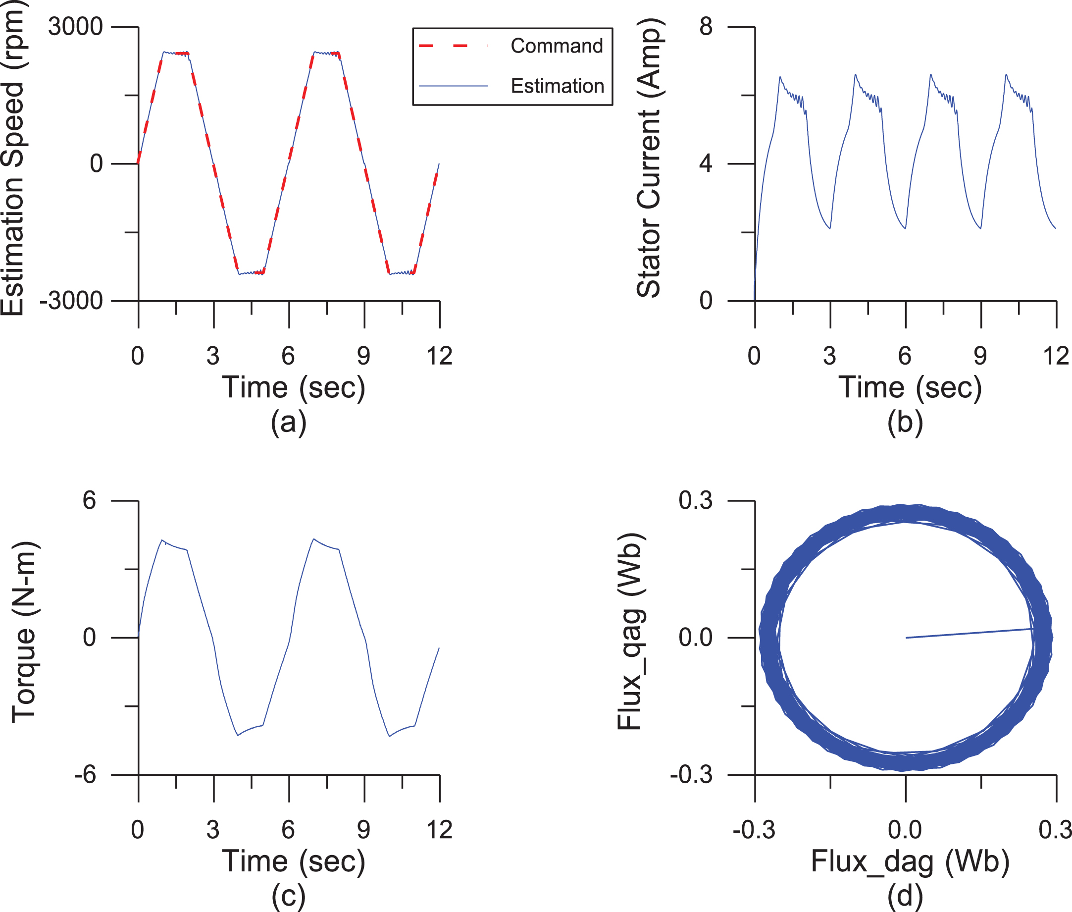
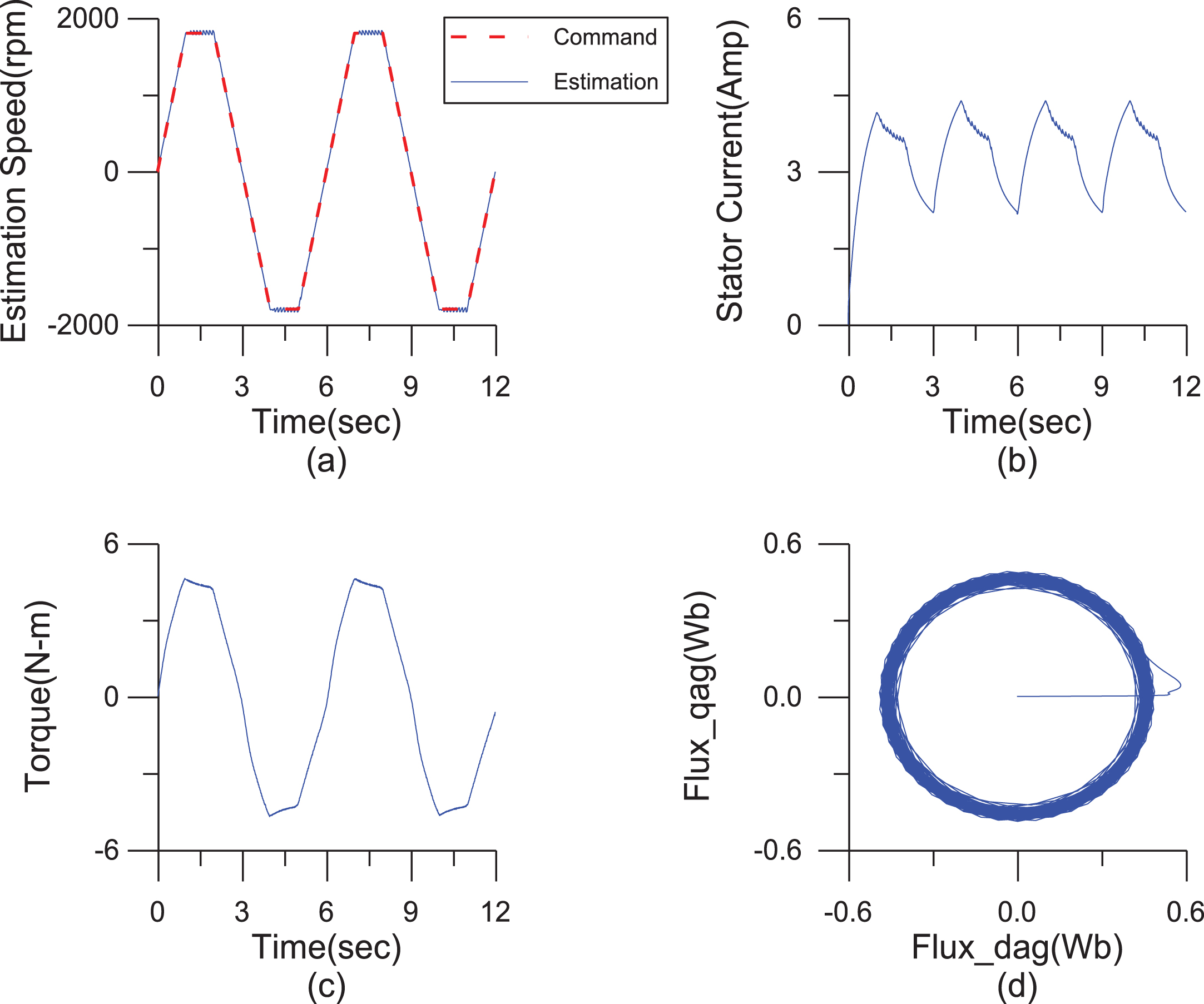
Simulated responses of the indirect AGFOC IM drive with loading 2 N-m at steady speed ±2400 rpm. (a)command (dotted line) and estimated (solid line) rotor speed, (b)stator current, (c)electromagnetic torque, (d)air-gap flux locus (q-axis air-flux V.S. d-axis air-flux).
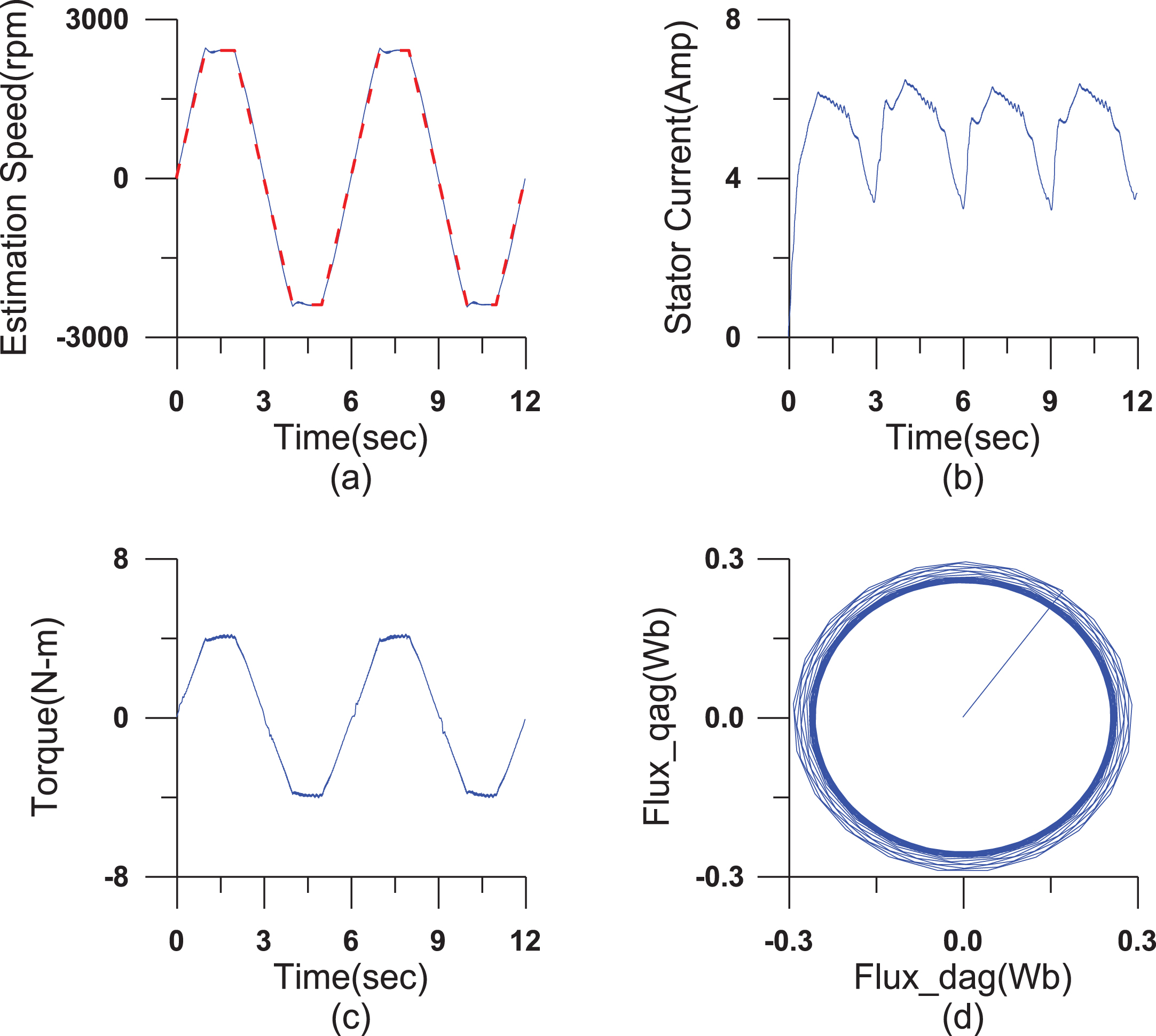
Measured responses of the indirect AGFOC IM drive with loading 2 N-m at steady speed ±2400 rpm. (a)command (dotted line) and estimated (solid line) rotor speed, (b)stator current, (c)electromagnetic torque, (d)air-gap flux locus (q-axis air-flux V.S. d-axis air-flux).
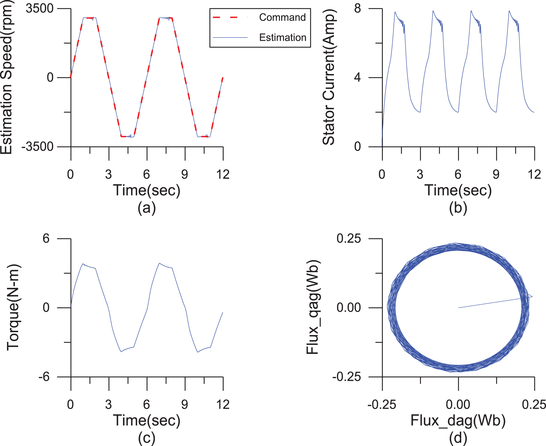
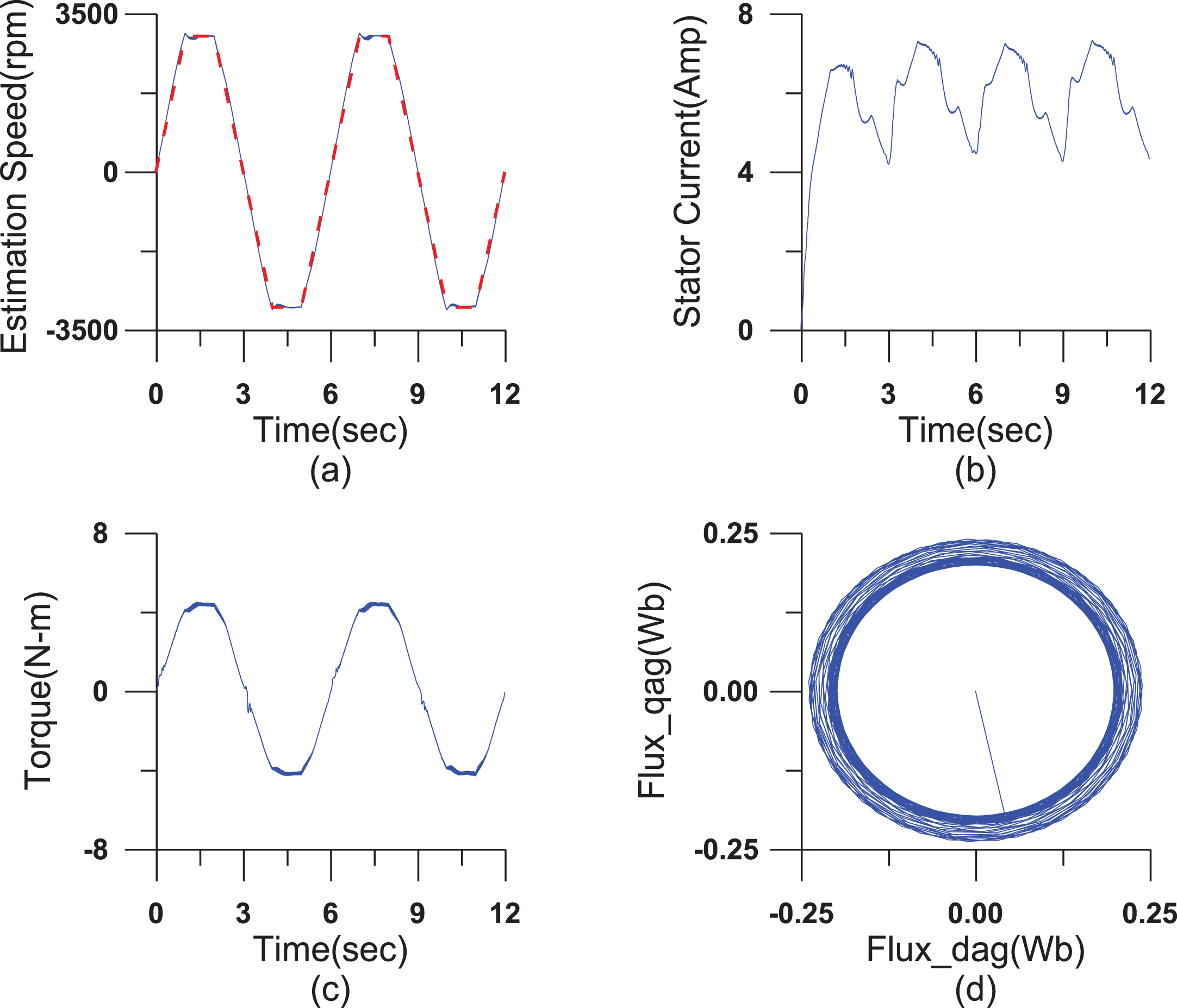
Simulated responses of the indirect AGFOC IM drive with loading 2 N-m at steady speed ±3000 rpm. (a)command (dotted line) and estimated (solid line) rotor speed, (b)stator current, (c)electromagnetic torque, (d)air-gap flux locus (q-axis air-flux V.S. d-axis air-flux).
Measured responses of the indirect AGFOC IM drive with loading 2 N-m at steady speed ±3000 rpm. (a)command (dotted line) and estimated (solid line) rotor speed, (b)stator current, (c)electromagnetic torque, (d)air-gap flux locus (q-axis air-flux V.S. d-axis air-flux).
MATLAB® ∖Simulink ®, Real-Time Workshop ®, and a TI DSP 6713-and-F2812 control card were used for synchronous speed on-line identification and speed estimation of the indirect AGFOC IM drive. A 3-phase, 220 V, 0.75 kW, Δ-connected, standard squirrel-cage IM was used (see appendix for motor parameters) in the experimental work. The control algorithm was simulated using Simulink after which the Real-Time Workshop was used to convert the simulated program into an execution program. The execution program was run on a DSP based control card and power stage and used to actuate the IM. In a running cycle, the speed command sequence was: forward direction acceleration from t = 0 to t = 1 sec, forward direction steady state running for 1 ⩽ t ⩽ 2 sec, forward direction braking operation to reach zero speed in the interval 2 ⩽ t ⩽ 3 sec, reverse direction acceleration from t = 3 sec to t = 4 sec, reverse direction steady state running for 4 ⩽ t ⩽ 5 sec, reverse direction braking operation to reach zero speed in the interval 5 ⩽ t ⩽ 6 sec.
The simulated and measured responses at first two running cycles are shown in Figs. 13–22. Each figure includes four responses: the estimated rotor speed, the stator current, the electromagnetic torque, and the air-gap flux locus. The simulated and measured responses with loading 2-N-m for the reversible steady state speed commands ±300 rpm, ±900 rpm, ±1800 rpm (constant torque mode), ±2400 rpm, and ±3000 rpm (constant power mode) are shown in Figs. 13–22, respectively.
The simulated and measured results for different operation conditions show that the proper estimated synchronous speeds can be obtained and verified by the circular shape of the air-gap flux locus. Accurate estimation of rotor speed can be acquired, better electromagnetic torque responses and stator current can be obtained under load conditions, and the weakening of the air-gap flux field locus is obvious in the constant power mode. This on-line MRAS reactive power based air-gap flux estimator, can accurately determine synchronous speed. The indirect AGFOC IM drive acquires better transient and steady response in both constant torque and constant power operation modes.
Conclusions
An indirect AGFOC IM drive using adaptive speed estimation has been developed using an MRAS synchronous speed identification scheme. The indirect AGFOC IM drive selects the stator current and air-gap flux as variables of state, and the drive can provide constant torque and constant power operation modes. The reactive power based MRAS acquires exact synchronous speed, and the estimated rotor speed is obtained by subtracting the slip speed from the synchronous speed. The simulation and experimental results at different reversible steady-state operation commands, including the constant torque (±300 rpm, ±900 rpm, and ±1800 rpm) and constant power modes (±2400 rpm, and ±3000 rpm) confirm the superior performance of this adaptive speed estimation indirect AGFOC IM drive.
Footnotes
Appendix
Induction motor parameters
| Poles | 4 |
| Base Freq. | 60 Hz |
| Base Volt. | 220 V |
| R s | 2.85 Ω |
| R r | 2.3433 Ω |
| L s | 0.1967 H |
| L r | 0.1967 H |
| L m | 0.1886 H |
| J m | 0.009 Nt - s2/m |
| B m | 0.00825 Nt - s/m |