
Abstract
In this paper, component values of analog active filters are selected based on the manufacturer’s values of E series. The selection is based on optimization algorithms and here one is nature-inspired meta-heuristic optimization algorithm, called Whale Optimization Algorithm (WOA), and another one is the physics-based method called Sine Cosine Algorithm (SCA), are used for active filter design. The capability of optimization of the above algorithms is evaluated by considering the two active filters of a 4th order Butterworth and State variable filter. The performances of each algorithm are analyzed by applying to above two different filter structures, where the component values are determined by making compatible with different E series manufacturer.
Keywords
Introduction
Discrete components are still used to design the analog active filter circuit, despite the rapid usage of integrated circuits in the electronics market. Discrete components such as resistors and capacitors are available in the market in the form of approximate E12, E24, E48, E96, and E192 series. They are produced in approximate logarithmic multiples of a defined number of constant values. Discrete components are chosen from these series for effective design of the analog active filter. However, an optimal design is not guaranteed when components are selected from the tighter tolerance series over wide decade range. Therefore, intelligent search methods must be incorporated to find the component values based on any of the preferred series which guarantees to meet the cost function defined.
The number of works for finding out the component values of filter compatible with one of the above series has been reported in various literatures. The application of different evolutionary techniques for determination of component values is the main and promising research area to design the analog active filter. In [1], optimal filter design for the microwave was aimed by applying particle swarm optimization (PSO) and finite element method. Optimal design method for 2-D recursive digital filters was developed through a genetic algorithm (GA) in [2]. Optimization for digital filter design through PSO and artificial bee colony algorithm was developed and reported in the literature in [3, 4]. Component value of passive filter synthesis was explored by means of genetic algorithms and in GP-based tree representation method respectively [5, 6]. Parallel Tabu search algorithm was carried out for selection of the component value of active filter compatible with E12 series. Ant colony optimization algorithm was used to design digital IIR filters [8]. An improved artificial bee colony algorithm was also incorporated into the optimal design of filter circuit [9]. In [10], a detailed comparative study on analog passive filter design with different evolutionary methodologies was tabulated. An automated passive analog circuit synthesis framework using genetic algorithms was explored in [11]. Unconstrained and constrained variables were handled toward the design of analog filter [12]. Differential evolution technique was used to optimize the component values of an analog filter [13]. In [14] adaptive immune genetic algorithm was applied to the determination of optimal component values of the passive filter. The Clonal selection algorithm, particle swarm optimization (PSO), Genetic algorithms (GA) and an immune algorithm was successfully applied to the optimal design of active filter [15–18]. Parallel Tabu search algorithm was applied for the design of active filter [19]. State variable filter was designed through PSO [20].
Meta-heuristic optimization algorithms are becoming more and more popular and mainly used for the design of active filter because of a simple concept, easy to implement, not falling in local minima and not requiring gradient information. It can be characterized as evolution-based, physics-based, and swarm-based methods. Evolution-based methods are inspired by the laws of natural evolution and examples are Genetic Algorithms (GA), Evolution Strategy (ES), Genetic Programming (GP) and Biogeography-Based Optimizer (BBO) [21–23]. The Physics-based methods use the physical rules exist in the universe. The most popular algorithms are Simulated Annealing (SA), Gravitational Local Search (GLSA), Big-Bang Big-Crunch (BBBC), Gravitational Search Algorithm (GSA), Charged System Search (CSS) [24–29], etc. The third group is nature-inspired social behaviours of living creatures. The few examples are Particle Swarm Optimization (PSO), Ant Colony Optimization, monkey search, and cuckoo search, etc [30–33].
This paper utilizes the two optimization algorithms, one is nature-inspired meta-heuristic optimization algorithm, called Whale Optimization Algorithm (WOA), and another one is the physics-based method called Sine-Cosine Algorithm (SCA) for optimal selection of component values of two active filters named 4th order Butterworth and state variable filter. The above two algorithms are the recent one and have been claimed the best solution during optimization. The claim has been guaranteed by applying the various benchmark functions of uni-modal, multi-modal and composite function to enable the capability of exploitation, exploration. In addition, the ability to explore the different region of search space, avoidance of local minima and convergence towards global optimum has been tested by using the different engineering single objective and multi-objective functions [37, 38]. The selection of component values should make compatible with the manufacturer preferred three different types of E series. In order to make compatible with E series, the coding is developed. The utilized filters are briefly reviewed in Section-2. The coding schemes and formation of the cost function for both filters are presented in Section 3. The brief review of WOA and SCA are discussed in Section 4 [37, 38]. The results are discussed in Section 5. In the end, the concluding remark is given.
Analog active filter
Analog active filters are realized by operational amplifiers (op-amp), with resistors and capacitors in their feedback loops, to synthesize the desired filter types such as low pass, high pass, and band pass. They are widely used in the separation of signals according to frequency bands, frequency selection decoding, estimation of a signal from noise, demodulation of signals, and amplifying elements [34]. The realization of op-amp creates high input impedance, low output impedance, and virtually any arbitrary gain without inductors which reducing the problems associated with inductors.
Butterworth 4th order filter
The component values of the Butterworth 4th order filter is optimally selected using optimization algorithms in such a way the values are compatible with the preferred E series. It is composed of two op-amps connected in cascade with four resistors and four capacitors as shown in Fig. 1. This filter produces a maximally-flat-magnitude response in the pass-band. The transient response shows good behaviours with moderate overshoot and ringing to a pulse input [17]. It can behave as a voltage control voltage source. The transfer function can be written as:
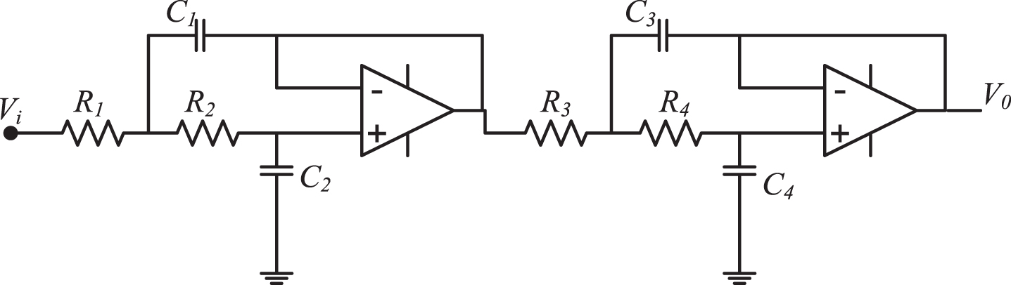
Fourth order Butterworth filter [35].
The cut-off frequencies and the quality factors can be written as:
Quality factor Q is characterized by resonator’s bandwidth relative to its cut-off frequency. Higher quality factor implies a relatively lower rate of energy loss as compared to its stored energy and vice versa. In this work, the cut-off frequency is chosen as 10krad/s and the quality factors Q1andQ2 are 1/0.7654 and 1/1.8478, respectively. In the conventional method, all four resistors value was chosen as 1KΩ. The values of capacitors were determined by Equations (2)–(4) and Equation (5). Therefore, the components values are not compatible with the E series. To make compatible with E series a coding scheme of resistors and capacitors is incorporated with cost function for minimization through optimization algorithms.
A state variable filter (SVF) is realized through a state-space model and can capable to produce simultaneously low-pass, high-pass, and band pass outputs from a single input. A second order SVF is shown in Fig. 2 and was well explained in [35, 36]. The low-pass output is assumed here to be the desired output and the performance parameters are specified by the pass band gain (G
s
) the cutoff frequency (w
s
) and quality factor (Q
s
) are written as follows:
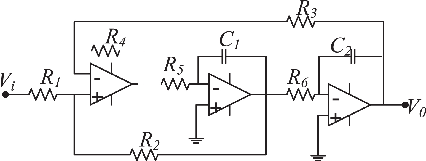
Second order state variable low pass filter [35].
The specification chosen for optimization are w
s
=10 k rad/s and Q
s
=0.707. The pass-band gain (G
s
) is not so much important in most applications since it can be compensated by other cascaded analogue circuits and hence for optimization it is chosen as unconstrained [36]. In conventional approach R1 to R6 except R2 is chosen as 4 kΩ each. The value of R2 is determined using Equation (6) and found to be 1.656 kΩ for the gain of 0.585. The capacitor values are determined using Equations (7) and (8). The value of C1 and C2 is 25 nF each. The transfer function of low pass second order state variable filter is expressed as:
In each decade, any of 12, 24 and 96 preferred values can be taken from standard E12, E24 and E96 series respectively. A coding scheme is presented based on probable values vary from three decade range for 4th order Butterworth filter as follows.
Similarly, for state variable filter the coding scheme is written as:
According to coding system, each component parameter must possess two variables. The range of each resistor is in the order of 103 - 106 Ω and 10-9 - 10-6 F for capacitor. The design onstraint of two variables of resistor and capacitor expressed in Ω and pF respectively given in Equations (12–14) for E12, 24 and 96 must be satisfied.
for E12 series
for E24 series
for E96 series
For minimisation through optimisation algorithm the error criterion should be formed. The criterion for cost function is the summation of cost function error of cut-off frequency and quality factor.
4th order butterworth filter
The cost function (CF) for minimisation is formed as [15, 40]:
The cost function for selection of component values of state variable filter can be written as:
The mathematical expressions for w s and Q s are given in Equations (7, 8). The value of w c is chosen as 10 krad/s.
The variables of cost function for 4th order Butterworth filter and State variable filter are increased from eight to sixteen because each component value is represented through two variables. The limit of representation as in Equations (12)–(14) for E12, 24 and 96 are the boundary constraint of cost function variables.
In order to estimate the component values of 4th order Butterworth filter and state variable filter and make compatible to E series, the two optimization techniques are selected in this paper. One is the nature-inspired meta-heuristic optimization algorithm, called Whale Optimization Algorithm (WOA) and the other one is the physics-based method called Sine Cosine Algorithm (SCA) [37, 38]. The minimization of the cost function with component representation for satisfying design constraint for making E series compatible is aimed to estimate the component values by the algorithms. In this section, the brief introduction and mathematical models of the above optimization algorithms are briefly reviewed.
Whale optimization algorithm (WOA)
The humpback whales are known for their special hunting method. They search the prey. Once the search is over, encircling and attacking the prey was carried out. The mathematical model of searching, encircling and attacking is expressed as follows: Searching for prey is the exploration phase which carried out by whales randomly according to the positions of each other. The mathematical model is as follows:
The position is updated by
If random values ‘A’ greater than 1 or less than – 1 are to force search agent to move far away from a reference whale.
The behaviour of encircling can be represented by the following equations:
After the best search agent is defined, the other search agents will hence try to update their positions towards the best search agent.
The vectors
There are two attacking approaches (exploitation phases). One is Shrinking encircling mechanism for A lying between 0 to 1 in 2D space. In this case the Equations 19 and 20 are used. The second is Spiral updating position based on value of random no ‘p’. The mathematical model is as follows:
The WOA algorithm starts with a set of random variables. In this case a set of 16 variables are chosen. The parameter
A sine-cosine algorithm is the novel population physics based method used for solving optimisation problem presented in literature [38]. The initial random candidates update by moving outwards and towards the best solution using mathematical model of sine-cosine function. The update equation is as follows:
Component values and performance of previously published algorithms for butterworth filter design
Component values and performance of previously published algorithms for butterworth filter design
Component Values and Performance of Previously published Algorithms for State Variable Filter Design
In this paper, WOA and SCA algorithms are utilized for active filter design by selecting the initial random variables of 16 numbers with aims to estimate the preferred values of resistors and capacitors of the selected circuit with minimum design error. The initial random variables are updated to find out the best fitness function based on cost function as the procedures are given in WOA and SCA algorithms. The results of component values are collected at the end of 1000 iterations for both algorithms. The population of the initial random variable is chosen 30 for WOA and 40 for SCA. The variable ‘n’ is selected as 3. The programme for SCA and WOA is developed in the MATLAB environment. The cost function with boundary constraint and compatible to E series for Butterworth filter is given for reference in A.1. The algorithms run for a number of times to get the best solution.
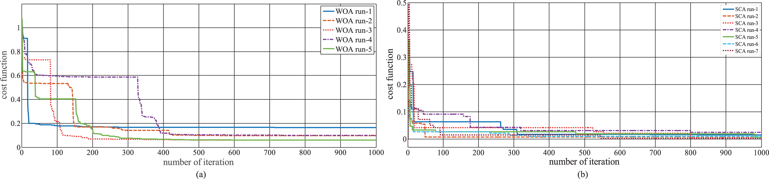
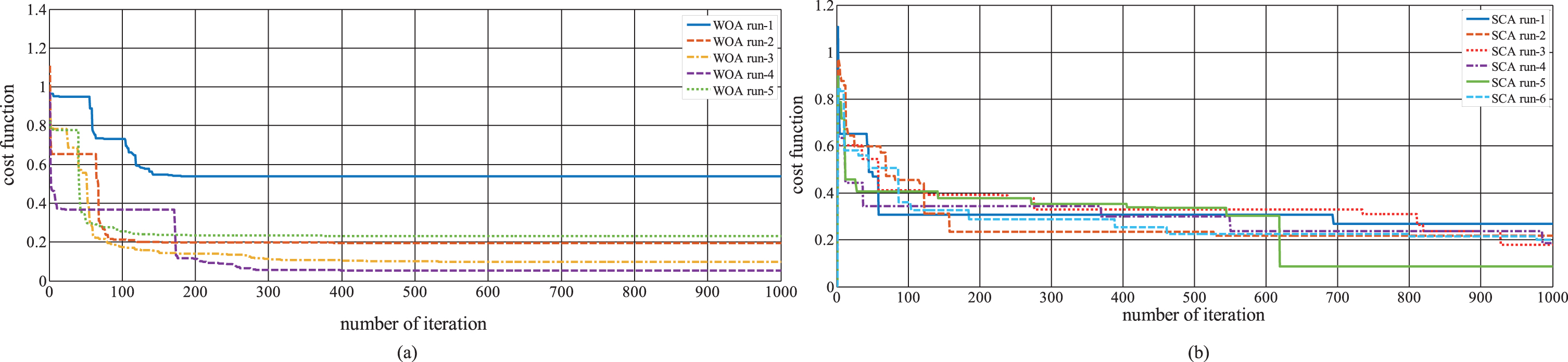
In Butterworth filter design, the components are selected from E12, E24, and E96 series by minimizing the cost function through both WOA and SCA algorithms. The component values with ΔW,ΔQ and value of CF for the above series are tabulated in Table 3 for both WOA and SCA algorithms. The value of CF for E12, E24, E96 are 0.059, 0.00832 and 0.0513 respectively for WOA. For SCA, the values are 0.127, 0.124428 and 0.086 for 3 different E series respectively. The results obtained from WOA are better than SCA. Both WOA and SCA can be comparable with the previously published results. CF values versus iteration number for different independent runs are plotted in Figs. 3–5 for WOA and SCA algorithms with different E series. In those figures, it can be seen that the number of iterations required to achieve the minimal points is slightly different and also the minimal point is different in each run.
Component Values and Performances of WOA and SCA Algorithms for Butterworth Filter Design compatible with E series
Cost function versus number of iteration of E 12 series with Butterworth Filter for (a) WOA and (b) SCA.
Cost function versus number of iteration of E 24 series with Butterworth Filter for (a) WOA and (b) SCA.
Cost function versus number of iteration of E 96 series with Butterworth Filter for (a) WOA and (b) SCA.
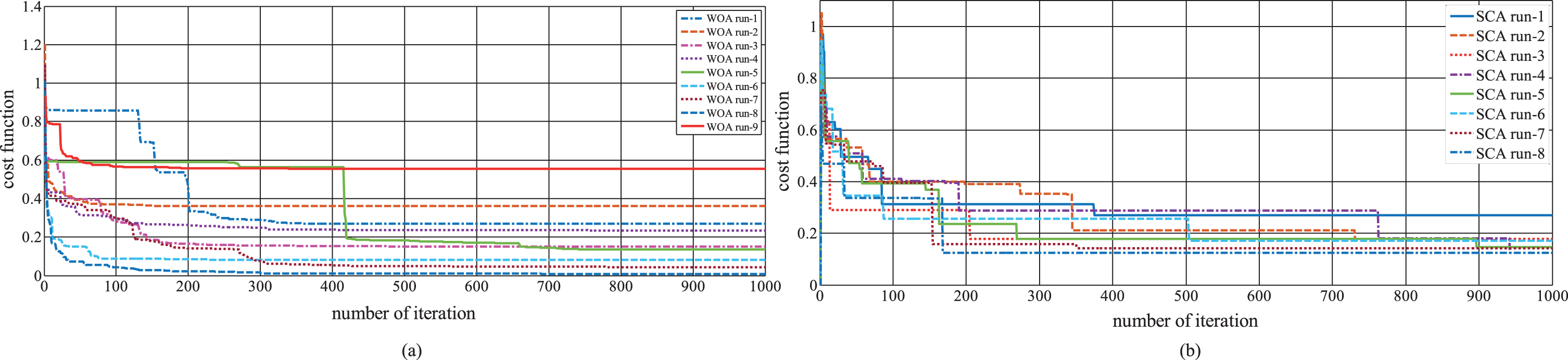
In state variable filter design also, the component values are selected from E12, E24, and E96 series by minimizing the CF through both WOA and SCA algorithms. The component values with ΔW, ΔQ, and value of CF for three E series are represented in Table 4. The best values are achieved with less number of runs in WOA algorithm. The cost function value is very closer to zero in WOA for all the three E series. The SCA algorithm also achieves good results. The value of CF in WOA for E12, E24, E96 are 6.673 * 10 - 5, 1.6 * 10 - 5 and 6.31 * 10 - 8 respectively.
Component Values and Performances of WOA and SCA Algorithms for State Variable Filter Design compatible with E series
The obtained result of CF for SCA are 1.23 * 10-4, 5.23 * 10-3 and 15.27 * 10-2. The convergence curve with iteration number for different independent runs is plotted for different E series optimized by WOA and SCA algorithms and shown in Figs. 6–8.

Cost function versus number of iteration of E 12 series with State variable Filter for (a) WOA and (b) SCA.

Cost function versus number of iteration of E 24 series with State variable Filter for (a) WOA and (b) SCA.

Cost function versus number of iteration of E 96 series with State variable Filter for (a) WOA and (b) SCA.
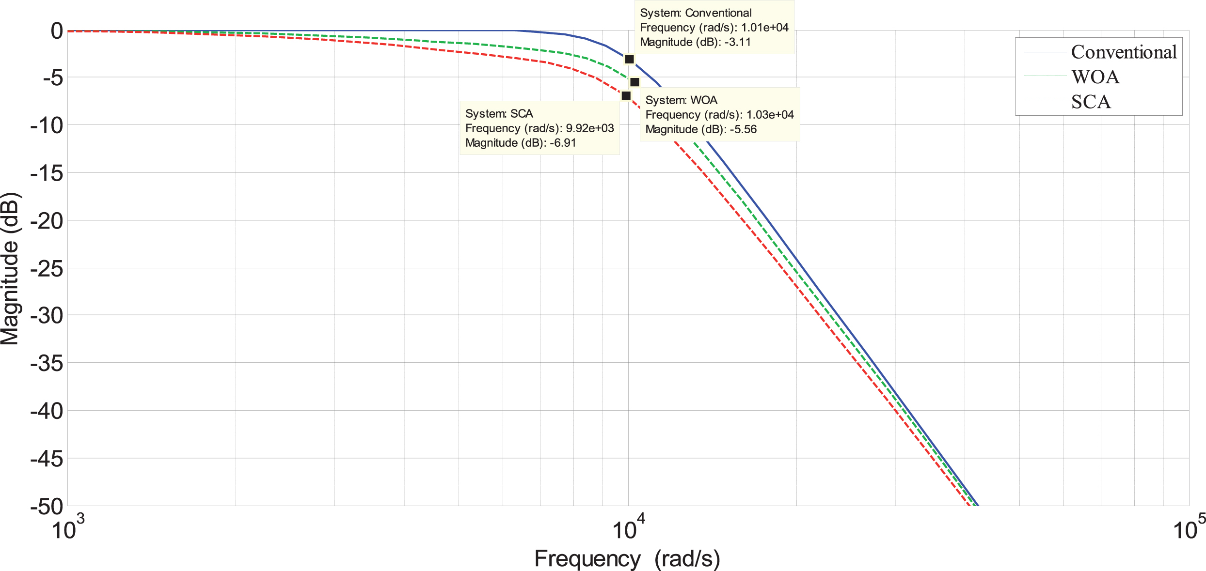
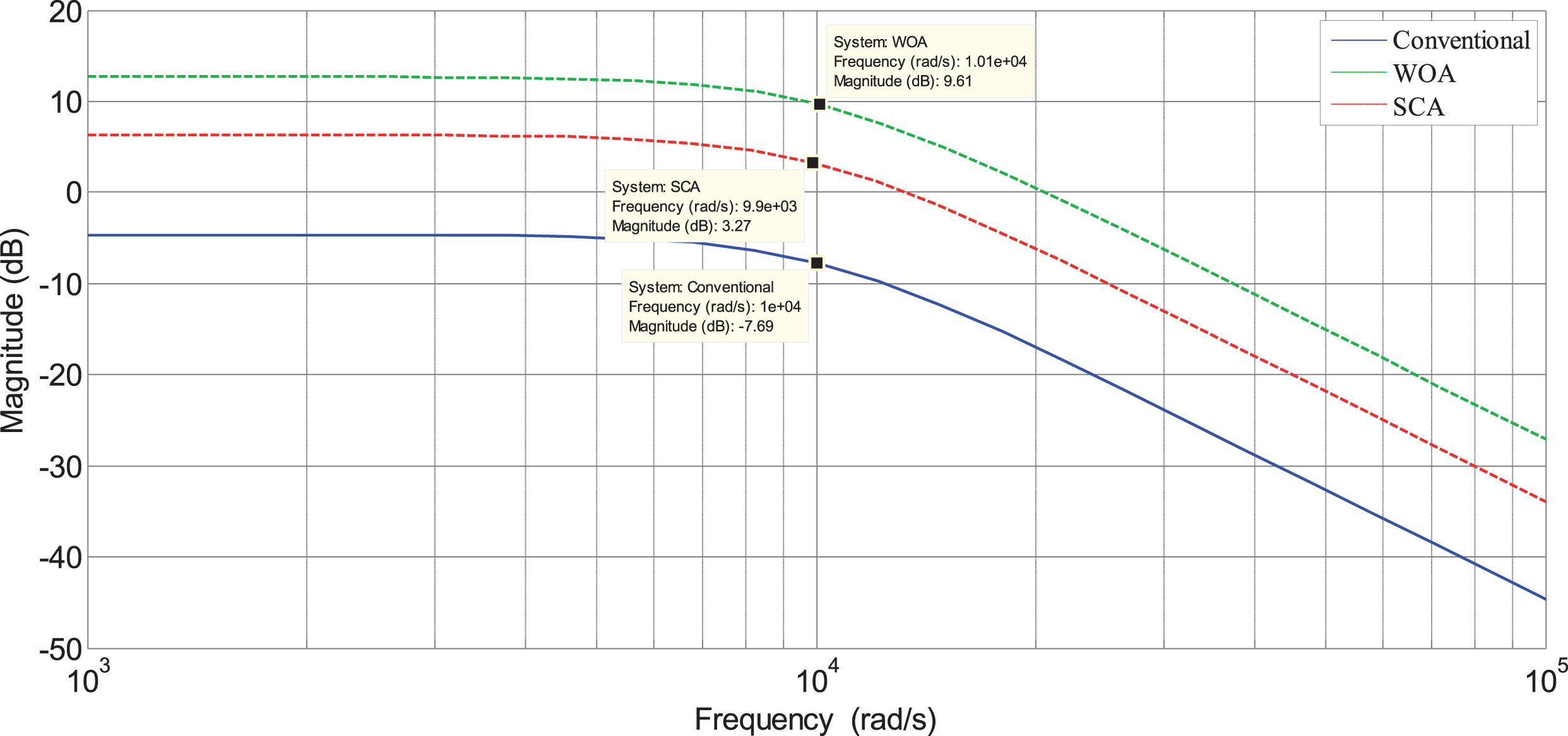
To demonstrate the accuracy of component values selection of Butterworth filter and State variable filter design methods through WOA and SCA algorithms, the frequency responses for individual E series are represented from Figs. 9–14. The gain value of Butterworth filter designed with WOA and SCA is same as the conventional design method since the filter is the unity gain filter. In the state variable filter, gain values are different since the cost function was formulated by considering the gain was unconstrained. From the frequency response results, it is concluded that the WOA provides a maximally flat response and less cut-off frequency deviation than the conventional method.SCA also provides a maximally flat response but the deviation of cut-off frequency is slightly more than WOA algorithm.
Frequency responses of Butterworth filter compatible with E12 series.

Frequency responses of Butterworth filter compatible with E24 series.
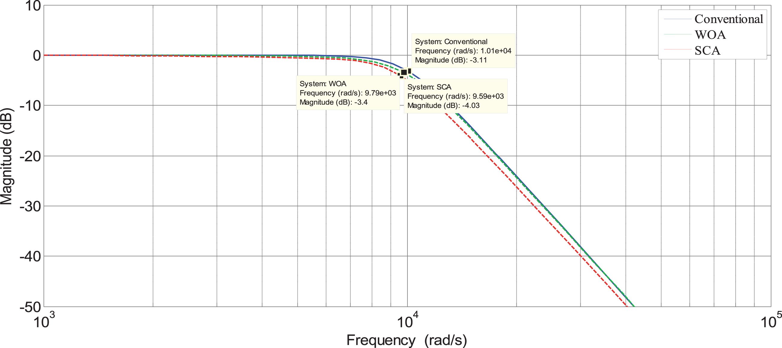
Frequency responses of Butterworth filter compatible with E96 series.
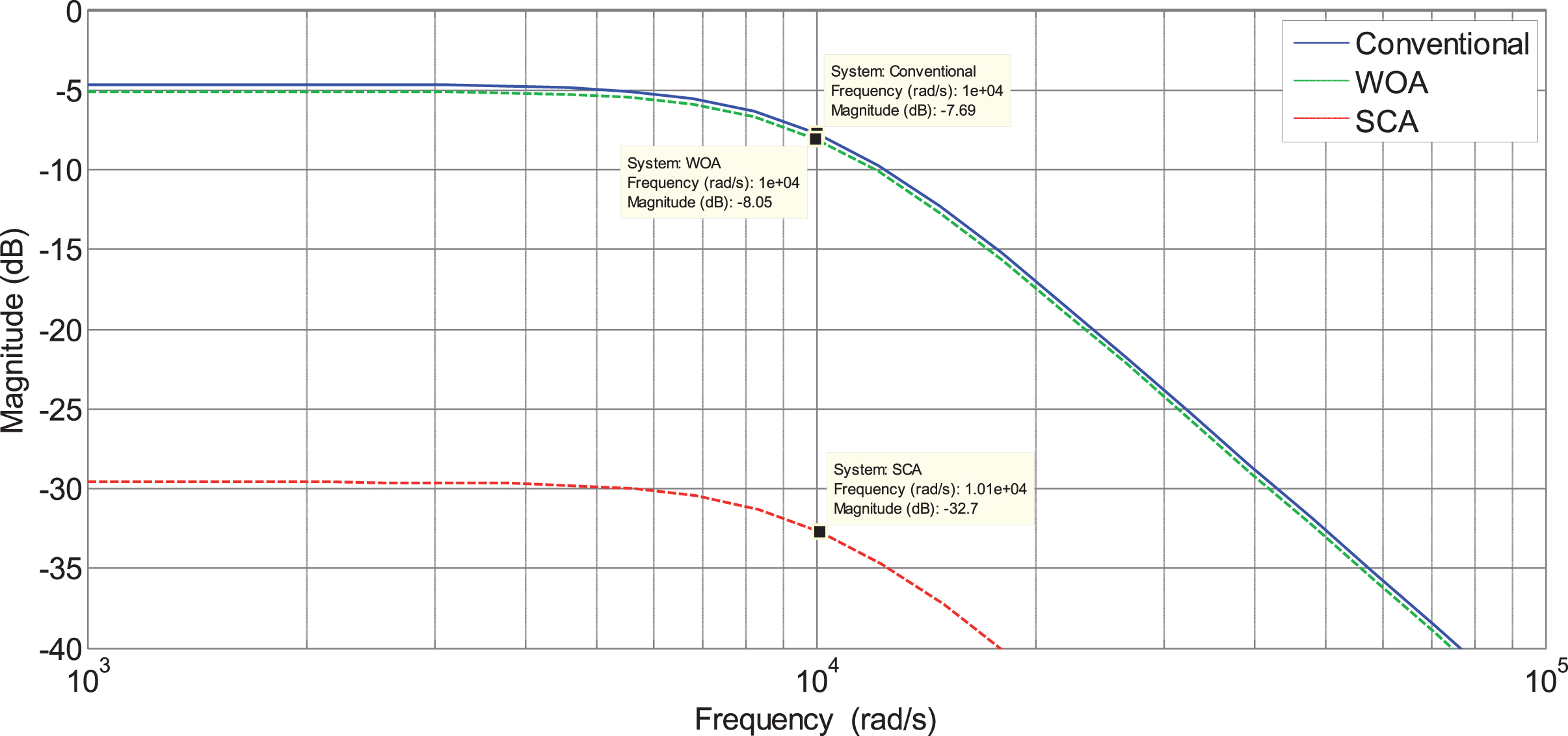
Frequency responses of state variable filter compatible with E12 series.
Frequency responses of state variable filter compatible with E24 series.

Frequency responses of state variable filter compatible with E96 series.
The magnitude of the gain of Butterworth filter compatible with E 12 series is obtained as –3.11 dB, –5.56 dB and –6.91 dB for conventional, WOA and SCA respectively at cut-off frequency close to 10 kHz. Correspondingly the magnitudes compatible with E 24 series are –3.11 dB, –2.69 dB, –5.26 dB and for E 96 series the values are –3.11 dB, –3.4 dB and –4.03 dB. This is apparent that the results obtained with these optimization techniques, WOA shows better results compared to SCA. For state variable filter, both WOA and SCA show improved results compared to the Butterworth filter.
The performances of both optimization algorithms WOA and SCA on analog active filter design have been investigated comprehensively. Both the algorithms have been utilized for both fourth-order Butterworth low-pass and second order state variable filters design to estimate the passive components of the filter which must be compatible with E12, E24 and E96 manufactured series. Since the filter performances are based on components values, an effort has been made to minimize the design error through the use of recent optimization algorithms. The analysis of results by applying optimization techniques confirms the WOA algorithm gives the smallest design error compared to SCA algorithms for both filters and as well as all E series. The result of the WOA algorithm has been achieved with less number of runs. In addition, The Table 2 confirms WOA achieves best frequency response compared to all previous works of literature analyzed state variable filter design through different algorithms. Though all the methods including SCA, performances have been better by minimizing the design error, the WOA outperforms other methods mainly in state variable filter design. For Butterworth filter design, the result obtained by WOA and SCA has been found satisfactory. This research helps to develop an optimized synthesis methodology for selection of component values of the analog active circuit design which can handle with all specified constrained in high accuracy. Because the filter performance is mainly based on the frequency response, the goal of design the filter is to follow the desired frequency response. Although there are the numbers of optimization algorithm, the WOA is the better choice to achieve the desired frequency response by strictly following the market availability the discrete parameters of resistor and capacitor. Additionally, the same optimization techniques may help for estimation of transistor sizes of analog circuits for semiconductor technologies and the result can be compared with older technologies in order to validate the strength of optimization capability.
Appendix A.1.
function o = F (x) % design of BUTTERWORTH FILTER
R1 = x(1)*100*10 ∧x (5);
R2 = x(2)*100*10 ∧x (6);
R3 = x(3)*100*10 ∧x (7);
R4 = x(4)*100*10 ∧x (8);
C1 = (x(9)*100*10 ∧x (13))*10 ∧ - 12;
C2 = (x(10)*100*10 ∧x (14))*10 ∧ - 12;
C3 = (x(11)*100*10 ∧x (15))*10 ∧ - 12;
C4 = (x(12)*100*10 ∧x (16))*10 ∧ - 12;
wc1 = 1/sqrt(R1*R2*C1*C2);
wc2 = 1/sqrt(R3*R4*C3*C4);
Q1 = sqrt(R1*R2*C1*C2)/(R1*C1 + R2*C1);
Q2 = sqrt(R3*R4*C3*C4)/(R3*C3 + R4*C3);
wc = 10e3;q1 = 1/0.7654;q2 = 1/1.8478;
dw = (abs(wc1 - wc) + abs(wc2 - wc))/wc;
dq = abs(Q1 - q1) + abs(Q2 - q2);
o = 0.5*dw + 0.5*dq;
format long
value = [R1,R2,R3,R4,C1,C2,C3,C4,dw,dq,o]; =[R1,R2,R3,R4,C1,C2,C3,C4,dw,dq,o];
end
fobj = @F; % Simulatoion results for filter design problem
lb = [0.1,0.1,0.1,0.1,2,2,2,2,0.1,0.1,0.1,0.1,2,2,2,2];
ub = [0.976,0.976,.976,0.976,4,4,4,4,0.82,0.82,0.82, 0.82,4,4,4,4];
dim = 16;