
Abstract
In this study, the performance analysis of Fuzzy Self Tuning (FST) control method for Bridgeless Power Factor Correction (PFC) converter is proposed. The Bridgeless PFC converter based on FST method operates AC line rectification to result in DC output voltage without full-bridge rectifier. The proposed method generates the duty cycles to provide higher Unity Power Factor (UPF) and lower Total Harmonic Distortion (THD) of input current, even if AC line voltage consists of harmonics. Although Ziegler-Nichols method is very important to tune the coefficients of PI control method, it cannot guarantee to be always effective. For this reason, this study investigates the design of FST control method that tunes the coefficients of Kp, and Ki gains that are used into inner and outer control loops. These parameters are self-tuned to make them more general, to achieve minimum steady-state error, and to improve the dynamic behavior such as overshoot. Performance of proposed system was implemented for 1 kW Bridgeless PFC converter board with a TMS320F2812 DSP. The simulation and experimental results are compatible with the limits for harmonic current emissions, IEC 61000-3-2 and show that the proposed method is better than traditional ones.
Keywords
Introduction
The distortion of AC line voltage and current are become a major problem for industrial applications where extensive power electronic circuits are used. These distortions are known as Total Harmonic Distortion (THD) result in low efficiency and in a decrease of Unity Power Factor (UPF). Although the load current is linear, nonlinear loads of other users cause distortion in AC line voltage. Therefore, efficiency and Power Factor Correction (PFC) has become more important subject for power converters [1]. It is desirable to achieve a fast dynamic response of the output voltage without causing input current distortion. Generally, the improving of the PF and the line current harmonics of the rectifiers are accomplished using PFC converters [2]. Besides, new techniques have been applied on active PFC techniques with improvements in power electronics [3]. Whether or not an isolation transformer is used, basic single step up/down converter topologies such as Buck-Boost [4], Sepic [5], Fly-back [6] and Cûk [7] are commonly used in PFC applications. These converters provide simple configurations for a wide range of input and output voltage conversion ratios, while active and passive components suffer from high voltages [8]. In addition, the inverse of the output voltage polarity of the Buck-Boost and Cûk converters makes them unsuitable for high voltage applications.
Bridgeless PFC converter was developed by Daniel M. Mitchell at the beginning of the 1980 s [9] and many implementations have been done so far, such as average current control [10], hysteresis control [11], average sliding mode control [12], predictive current control [13] etc. The topology has an important advantage than the others with lower switching losses and minimum number of switches [14]. The main task of the control strategy provides the pure sinusoidal input current and verifies the desired output voltage value with low ripple [15]. In conventional PFC converters, there is an important disadvantage when they are controlled and used AC line voltage directly [10]. However, this problem is solved by the way of enforcing input current based on the input voltage at zero crossing points [13].
In this study, the most popular two control methods are reviewed and compared, in order to highlight advantages and drawbacks of each solution. The proposed control method used for bridgeless PFC converter is Fuzzy Self Tuning (FST). This control method is compared with the conventional PI control method to prove the robustness of FST. Traditional approached conventional PI controller is widely used in PFC applications [16]. PI controller has a good static performance especially for linear and time-invariant systems, but it shows poor dynamic performance in nonlinear, time varying and uncertain systems [17].
In the past years, control of the converters was provided by analog control techniques [18]. However, as a result of technological developments, digital signal processors (DSP) have begun to be used instead of analog processors to control of converters. DSP can improve the converter performance in a number of ways through the using advanced control methods [19]. In this study, it is analyzed to adjust duty cycles of the bridgeless PFC converter switches for pure sinusoidal input current and constant output voltage by using the FST control method and performance evaluation is carried out.
Fuzzy logic control (FLC) is a technique that provides robust control over nonlinear and adaptive uncertainties. Besides, the Mamdani method is widely accepted to capture expert knowledge. It allows us to define our expertise in a more intuitive, more human-like way. However, the Mamdani method requires a significant computational burden. Due to the interpretive and intuitive nature of the rule base, the Mamdani method is widely used especially for decision support applications [20]. Fuzzy controllers are in different types. Some of them are based on fuzzy logic controller while some of them are based on PI controller that their coefficients are adapted by a fuzzy system. In this paper, the second one is used with Mamdani method to control the bridgeless PFC converter. Fuzzy based controllers have been applied to a wide range of engineering problems, which have particularly nonlinear dynamics. In [21], a multi-objective control strategy using adaptive fuzzy PI (AFPI) controller for grid-interactive converter (GIC) is presented. In the proposed method, the gains of the PI controller are dynamically adjusted by the fuzzy logic based controller according to the system operation conditions. In [22] a fuzzy-based PI controller is proposed for a chopper-based load emulator in AUT micro grid for both islanding and grid connected operation modes. Fuzzy control has been applied as a main controller for renewable energy systems in [23]. Drive problems of doubly fed induction generators used in wind turbines are also solved by FST control method in [24]. In [25], the proposed self-tuning fuzzy PID controller that incorporates the advantages of both fuzzy control and PID control can effectively improve the performance of the PWM DC–DC converter. Also, [26] presents a development of a self-tuning fuzzy PID controller to overcome the appearance of nonlinearities and uncertainties for the DC-DC converter.
In this study, FST controller is used with feed forward into the control algorithm of bridgeless PFC converter to improve disadvantages of conventional controllers. The FST controller is applied into outer and inner loops, which are used for regulating of output voltage and eliminating the harmonics of input current. Test results show a better performance for FST compared to the conventional types for the variation of AC line voltage and load parameter changes. In addition, this study satisfies IEC 61000-3-2 and IEEE 519–1992 harmonic standards [27].
In this paper, operating principle and mathematical models of Bridgeless PFC converter are given in Section 2. The control strategies of FST controller and comparing with the conventional PI control method for bridgeless PFC converter is described in Section 3. The simulation and experimental analysis of test results are studied in Section 4. The conclusion part is given in Section 5, respectively.
The circuit description and operation
In this study, AC-DC bridgeless converter that is shown in Fig. 1 is controlled to obtain unity PF and lower THD of input current. One of the most significant advantages of this circuit is that conduction losses of switches are less than the other similar PFC converters. It is provided by the minimum number of switches. This topology consists of two single-phase boost converter without the input rectifier as if in other circuits.
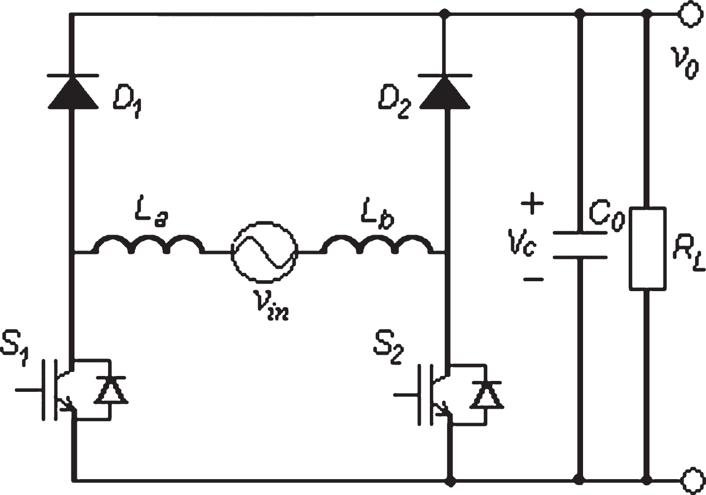
The topology of AC-DC bridgeless converter.
In Fig. 2, the positive and negative half cycles of applied line voltage to the bridgeless converter topology is given. The mathematic models for positive half cycle of AC line voltage are given in Equations (1 and 2) [13]. If the switch, S1 is turned on, the current flows from switch S1 to body diode of S2. At that moment, inductors are charge and the capacitor energy flows through the load (0 < t < dTs).
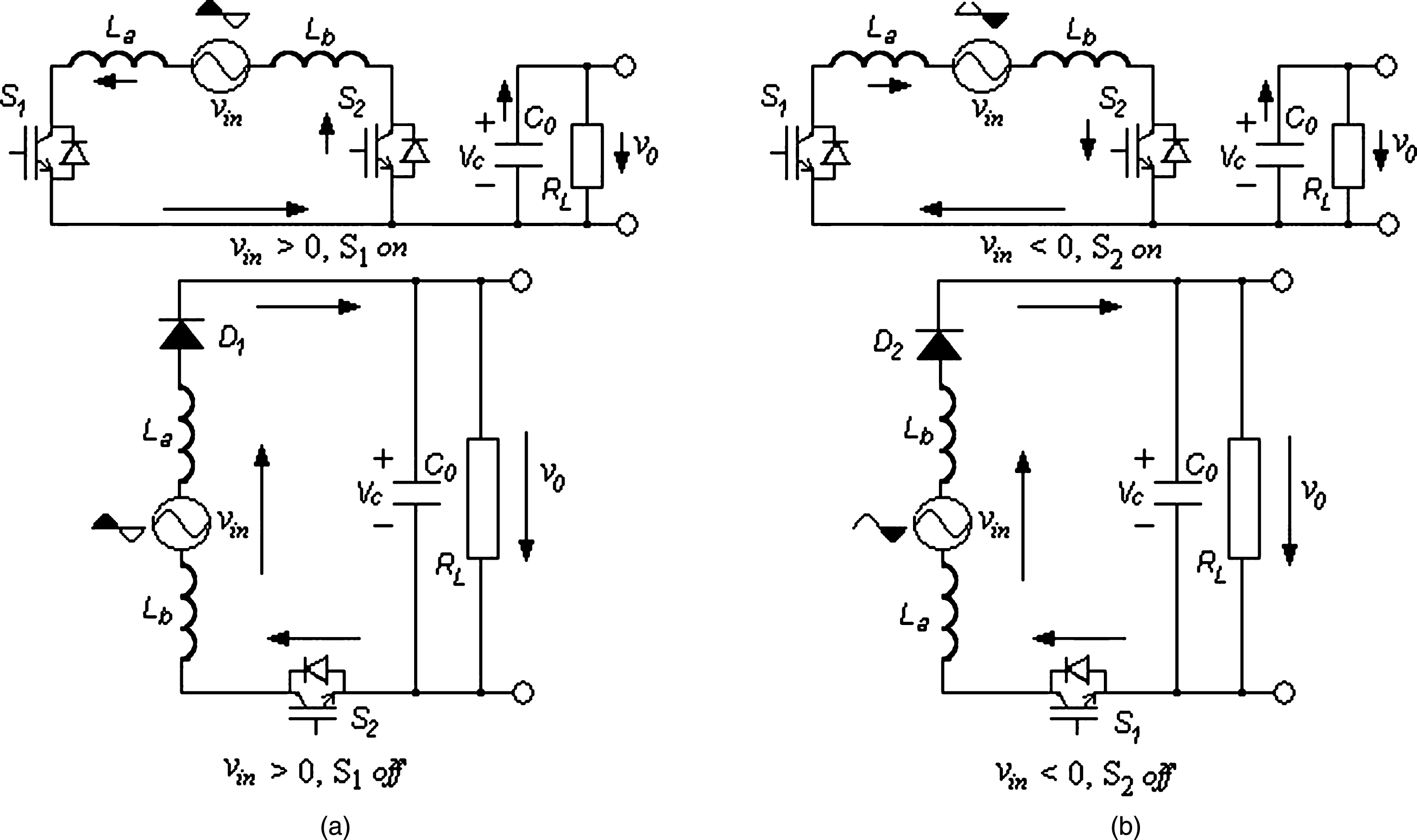
Positive and negative half cycles of the switches in bridgeless PFC converter: (a) Positive half cycle, (b) Negative half cycle.
If the switch, S1 is turned off, the current flows from D1 to the parallel connected capacitor and load, then current flows through the body diode of S2 (dTs < t < Ts). The equations of this period are given below [13].
The equations, which are given above, used in the positive half cycle of the AC line voltage are the same as for the negative half cycle. Related models in the time interval 0 < t < dTs and dTs < t < Ts can be written as follows, respectively [13].
State-space averaged switch approach for this converter is given below in the case of Continuous Conductive Mode (CCM) [13].
Where Ts, L = La + Lb, d = Ton/Ts, C0, and RL are the switching period, inductor value, duty cycle ratio, parallel output capacitor value and load resistor, respectively.
In this paper, CCM is operated for the bridgeless converter. Although, the current that is stored in inductors never goes to zero state in CCM, the current goes to the zero in discontinuous conduction mode (DCM) during the switching cycle. The operation of CCM for PFC circuits achieve the high quality and small system size for the industrial applications (>200W). Besides, DCM PFC circuits are frequently used lower power applications like small converters and adapters for the purpose of simplicity and low system costs (<200W) [28, 29].
Many types of control methods are widely used for PFC converters in industrial applications. The PI controllers are the most widely used controller in power electronics processes because of their simplicity and practicality. Besides, many tuning methods have been proposed for PI controllers to improve their abilities. Our purpose in this study is comparison of FST and conventional PI control method for bridgeless PFC converter. Even though distorted AC line voltage is implemented to the converter, the FST control method is implemented into inner current and outer voltage loop of control algorithm for eliminating input current harmonics. It also provides minimum steady-state error and robustness. In addition, it improves dynamic behavior and reliability of the system. In this section, the mathematic model of conventional PI and FST control methods have been performed, respectively.
Implementation of conventional PI control method
In this section, the systematic way of designing the most appropriate PI parameter for the proposed system to achieve fast dynamic response with reduced overshoot and settling time is explained. Control of the bridgeless PFC converter is accomplished using the cascade control loops which names are outer and inner loop. During the selection of Kp and Ki parameters, nonlinearities are neglected and adjustments are made by adopting a linear system. The inner loop is designed to achieve fast response for the AC line current. On the other hand, the main aim of the outer loop is to provide maximum stability and regulation for the output voltage. The controller is designed in Matlab using a “sisotool” graphical user interface based on the Zeigler-Nichols method, which allows the closed loop frequency response to be changed interactively by changing the pole-zero position of the PI compensator. In this study, the appropriate values of proportional and integral gains are chosen and given in Table 3.
By using these values, bode plot for the current control loop is shown in Fig. 3(a). It is seen that the phase margin is 54.8° and the frequency is 8140 rad/s. The frequency response graph shows that the system is stable. In addition, bode plot for the voltage control loop is shown in Fig. 3(b). It is seen that the phase margin is 35.8° and the frequency is 1846 rad/s. The frequency response graph shows that the system is stable and it has less oscillation.
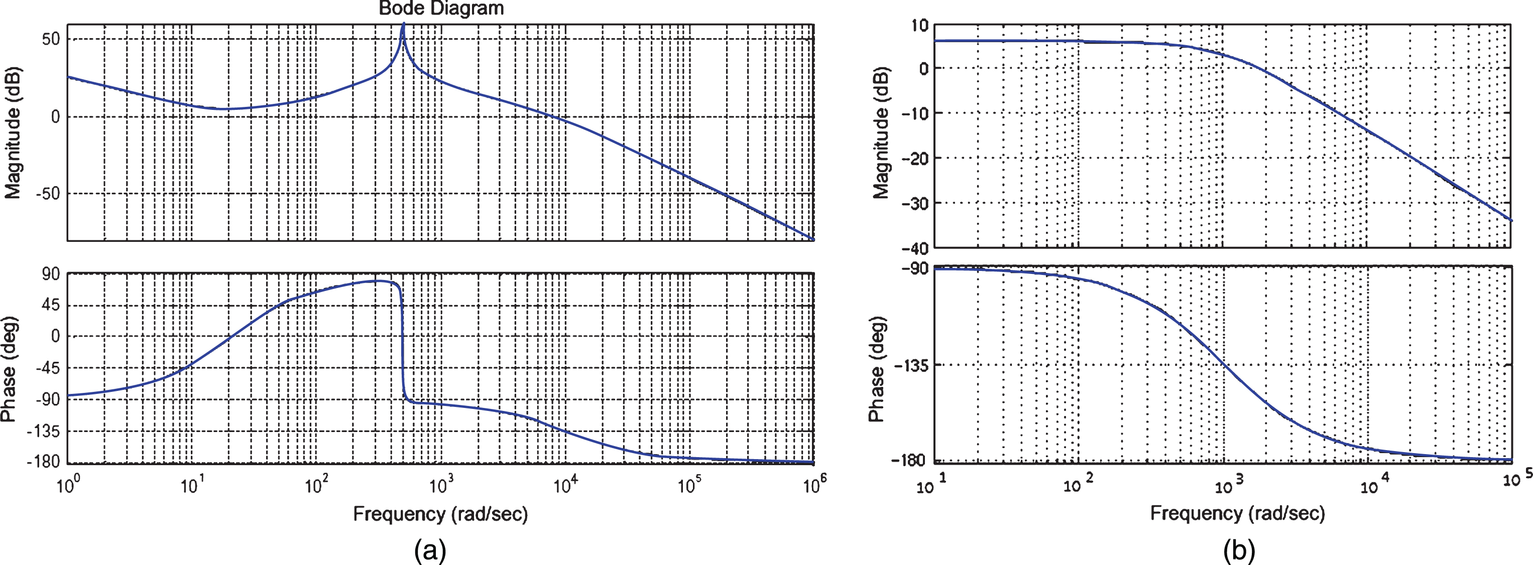
Open loop bodes plot (a) for the current control loop, (b) for the voltage control loop.
In this conventional method, the average value of inductor current and output voltage is sampled, and used to obtain duty cycle for the switching process of bridgeless PFC converter. A reference current is provided that represents the desired average current to obtain output DC voltage with lower THD and UPF. The basic equations of reference current and controller output (u) for conventional PI control method can be expressed as follows [13].
Kp1 + Ki1/s and Kp2 + Ki2/s is the voltage and current error amplifier that are given in Equations (8 and 9), respectively. In addition, controller output u, which is given in Equation (9) is compared with the high frequency ramp signal for the purpose of generate duty cycles for switching process. It is well known that PI controller show poor control performance and incapability for the large variations of line voltage and power. Due to the constant Kp and Ki parameters of the conventional PI controller, FST control method is developed to tune the constant values.
The most popular control method of PI controller is used for industrial applications due to its steady state and transient response performance in time-invariant systems that the parameters, Kp and Ki are always constant during the system process. While environmental conditions or dynamics variations are occurred, the PI controller is inefficient, because of the controller parameters give uncertain behavior. Instead of this method, FST control method is used for dynamic variations and does not need to know the whole system model. If the system is sophisticated and undefined, FST control method shows the better performance than the conventional one. Another major advantage of FST is to reaches steady state in a very short time with a small overshoot and very short rise time. Thus, the parameters of this controller that are used into inner and outer control loops are self-tuned to make them more general by FST control method.
Bridgeless PFC converter has two loops for the purpose of control the input current and output voltage. The shape of the inductor current is controlled by the inner loop and the output voltage is controlled by the outer loop and is held constant. In the outer loop, the output voltage is measured and compared to the given reference value and then error is obtained which is used as an input for the other FST controller. In the inner loop, inductor current is compared with a pure sinusoidal reference current that are obtained from zero crossing points of line voltage. Thus, the reflection of line voltage harmonics to the line current is eliminated by this technique. The block diagram of FST control strategy for bridgeless PFC converter is given in Fig. 4.

The block diagram of FST control method.
FST controller adjusts the Kp and Ki parameters of a PI controller using fuzzy adjuster. There are two inputs for each parameter in fuzzy control. “e” is the error between the desired positions with the output and “de” is the amount of the change in the error, in other words derivation of error. To give nonlinear output according to the changes of error and derivative of error the PI parameters are adjusted using the fuzzy controller.
The membership functions used in the inputs and output fuzzy sets are given in Fig. 5. According to the precision and control requirements, it is appropriate that five levels are usually selected. The linguistic values of input and output linguistic variable are positive big (PB), positive small (PS), zero (ZE), negative small (NS) and negative big (NB) which have been assigned to the “e”, “de” and output. The ranges of inputs are both pu units and change from –1 to 1, also output coefficient “τ” changes from 0 to 1, respectively.

Membership functions: (a) error, (b) change of error, (c) output.
The minimum and maximum limits for [Kp_min, Kp_max] and [Ki_min, Ki_max] have been set for the range of PI controller parameters using FST control method with a variety of tests by Matlab/Simulink program. The most suitable values are obtained as a result of the simulation. The ranges of each parameter for voltage control block, Kp ∈ [10 - 37], Ki ∈ [500 - 950] and current control block, Kp ∈ [2 - 12], Ki ∈ [900 - 1000] are obtained and used by fuzzy sets with following equations;
Thus, Kp and Ki coefficients of voltage and current control blocks are obtained:
Generally, fuzzy rules depend on the type of controllers or practical experiences. To obtain the parameters in the ranges given Equations (10 and 11), there is need to adjust fuzzy rules.
In the proposed control method, the modification rules for “e” and, “de” for parameters (
If “e” and “de” is negative big, the smaller
If “e” and “de” is zero,
If “e” and “de” is positive big, the bigger
The variations of error, derivative error and outputs are presented by linguistic expressions that are given in Table 1. The parameters are tuned by using fuzzy controller, which provide nonlinear conditions. In the next section, it will be discussed the impact of those variations on the system.
The rule base of proposed system
The efficiency of the proposed control method is analyzed by quantitative and comparative assessment tests. The performance of the bridgeless PFC converter is analyzed according to the variations of input voltage, frequency and components values. The comparison has been done according to the input current THD, PF and dynamic behavior of the converter. Therefore, the bridgeless converter is operated in CCM mode.
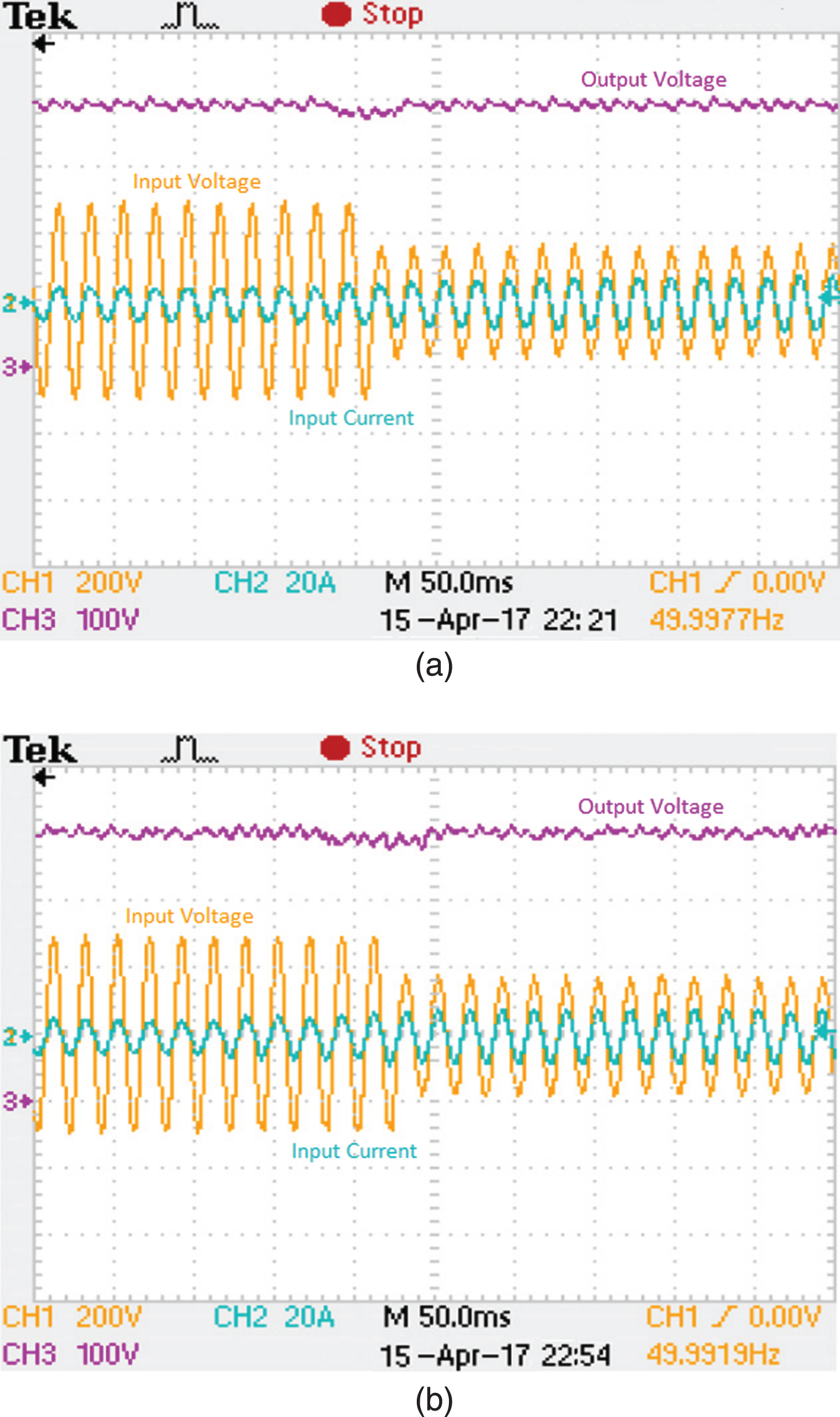
The parameters that are used for the converter are given in Table 2. Figure 6 shows the waveforms of the input current, input voltage and output voltage for the FST and conventional PI control method at rated load. In this operation conditions input voltage rms value has been selected 220Vrms/50Hz, output power has been selected 1kW, and output voltage has been selected 400Vdc. By using these values, the value of PF and the variation of input current THD are 0.99/0.99 and 1.34% /1.71% for the FST and PI control method, respectively.
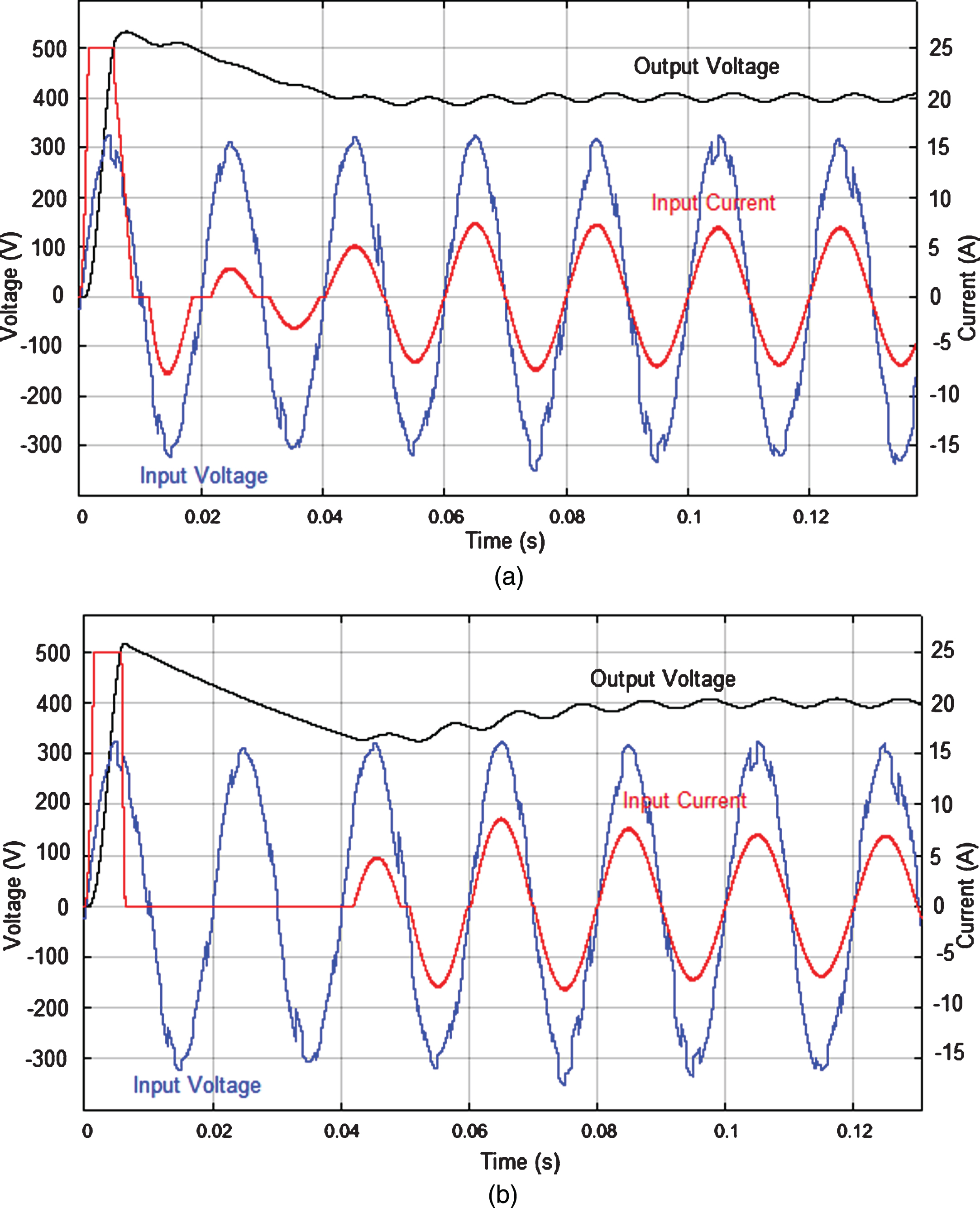
Measured input current, input voltage and output voltage waveforms of control methods: (a) FST control method, (b) Conventional PI control method.
Parameters used in bridgeless PFC converter topology
Controller constants and time domain specification
∼: variable according to the changes *: current control variables. **: voltage control variables.
Although rise time for FST controller is bigger than PI, steady state error of FST is less and settling time is much shorter than conventional PI control method. In addition, the dynamic behavior results of bridgeless converter that is controlled by two control methods are given in Table 3.
Figure 7 shows the waveforms of the input current, input voltage and output voltage when the load of the PFC converter is changed from full load to half load and then the load is changed from half load to full load in steady state.
The value of PF and the variation of input current THD for the output power (1 kW to 0.5 kW and 0.5 kW to 1 kW) are 0.99/0.99 and 1.34% /2.34%, respectively for the FST control method. The value of the PF and the variation of input current THD for the output power (1 kW to 0.5 kW and 0.5 kW to 1 kW) are 0.99/0.98 and 1.71% /2.64%, respectively for the conventional PI control method. According to this test values, the performance of FST control method is better than conventional PI controller.
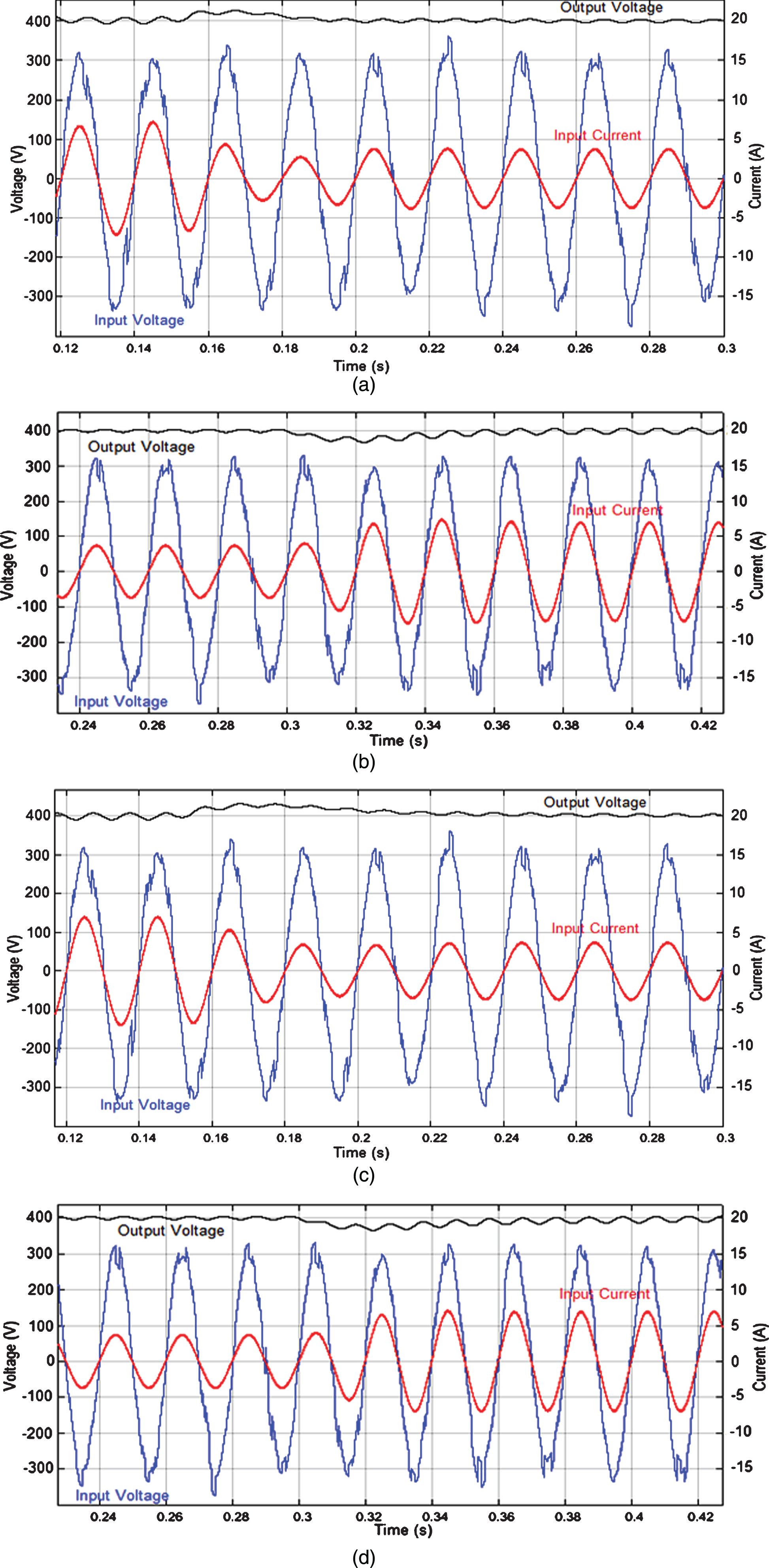
The response of load variation: (a) from 1 to 0.5 kW for FST control method, (b) from 0.5 to 1 kW for FST control method, (c) from 1 to 0.5 kW PI control method, (d) from 0.5 to 1 kW for conventional PI control method.
Figure 8 shows the waveforms of the input current, input voltage and output voltage when the input voltage of the PFC converter is changed from 220 to 110 Vrms. The output power is held constant (1 kW) during a change of input voltage. The value of the PF and the variation of input current THD for the input voltage (220/110V rms ) are 0.99 and 2.1%, respectively for the FST control method. The value of the PF and the variation of input current THD for the input voltage (220/110Vrms) are 0.98 and 2.53%, respectively for PI control method.
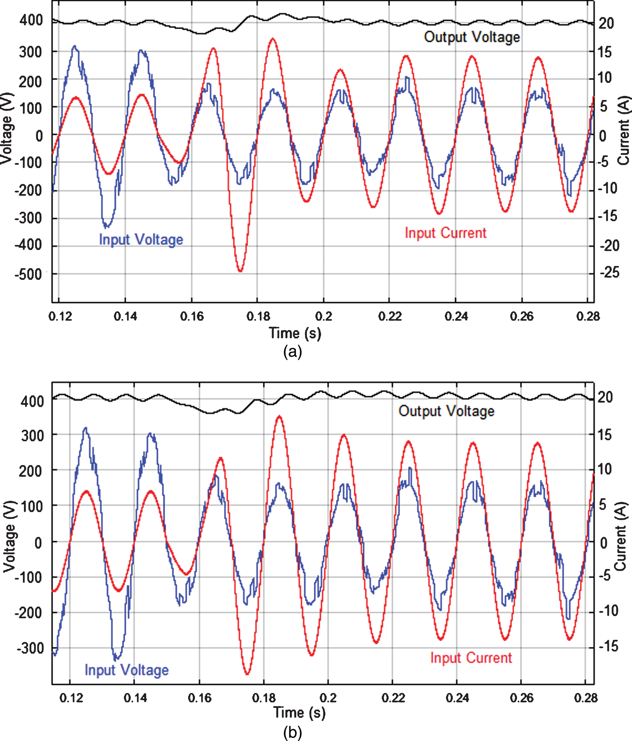
The response of line voltage variation: (a) from 220 to 110Vrms for FST control method, (b) from 220 to 110Vrms for conventional PI control method.
The control of the system for different conditions of operation is tested using Texas Instruments DSP TMS320F2812. For taking data, LEM LV25-P and LEM LTS25-NP sensors are used. The laboratory set up that is used for test studies are given in Fig. 9.
To show the FST control method that satisfies the power factor, a zoom in view of the input current waveform during the zero crossing points of AC line voltage is given in Fig. 10.

Experimental set-up of PFC converter.
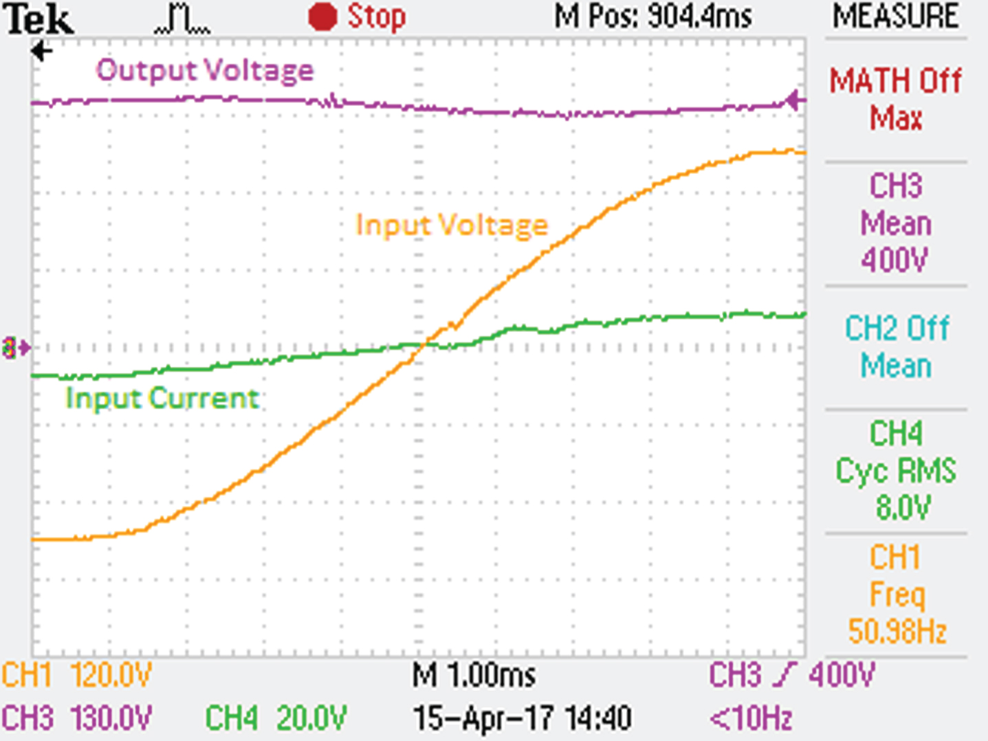
The zoom in view of input voltage, input current and output voltage waveforms during the zero crossing point of AC line voltage.
The effects of the load variation on FST and PI control methods of the bridgeless converter experimental performance results are analyzed in Fig. 11. In this analysis, the input voltage is 220 Vrms and the output voltage set value is 400 Vdc. The input voltage, output voltage and the input line current responses for a decrease of 0.5 kW in load (change from 1 to 0.5 kW) and for an increase of 0.5 kW (change from 0.5 to 1 kW) are shown in Fig. 11.
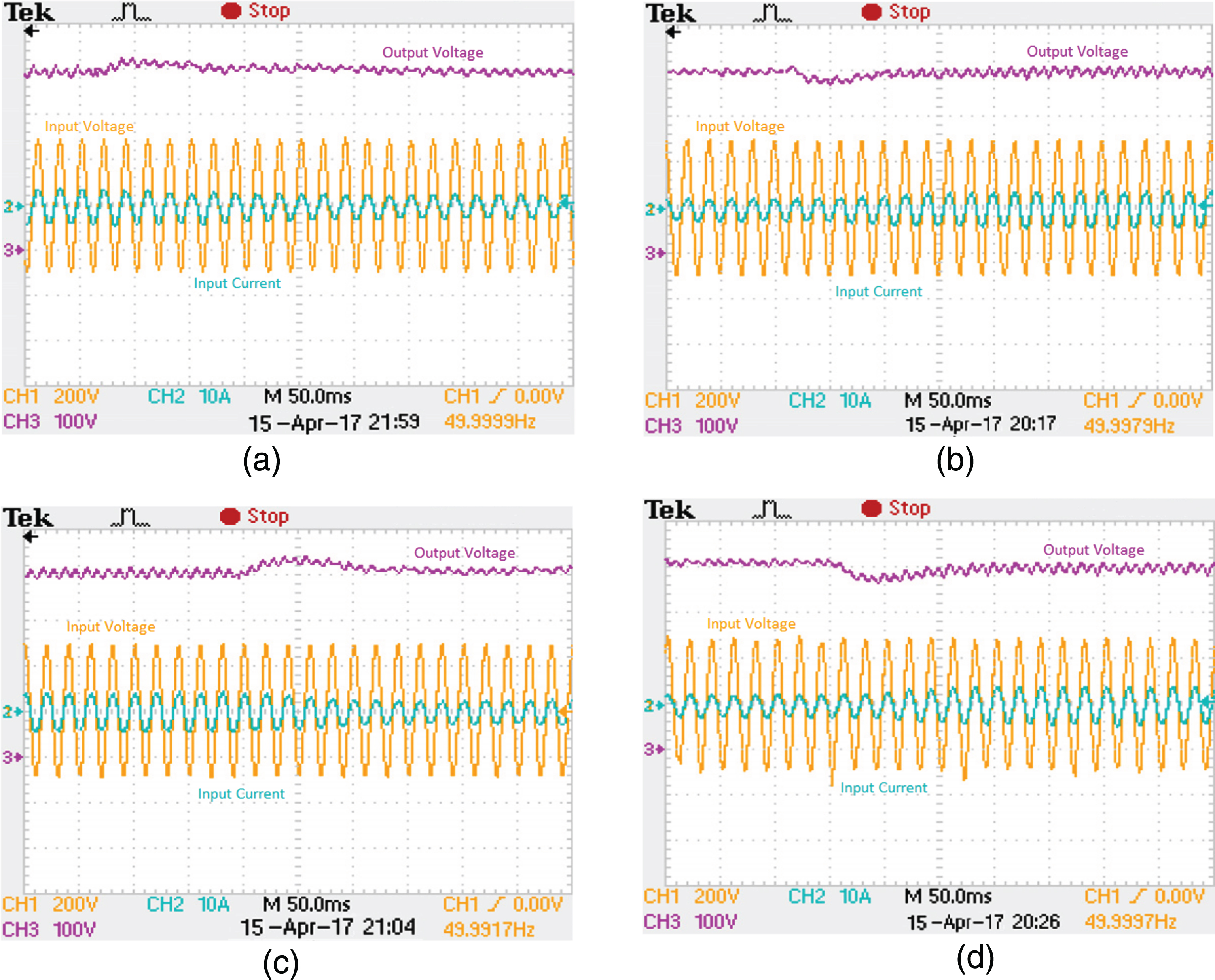
The response of load variation: (a) from 1 to 0.5 kW for FST control method, (b) from 0.5 to 1 kW for FST control method, (c) from 1 to 0.5 kW PI control method, (d) from 0.5 to 1 kW for conventional PI control method.
The value of PF and the variation of input current THD for the output power (1 kW to 0.5 kW and 0.5 kW to 1 kW) are 0.99/0.99 and 1.48% /2.45%, respectively for the FST control method. The value of the PF and the variation of input current THD for the output power (1 kW to 0.5 kW and 0.5 kW to 1 kW) are 0.99/0.98 and 2.05% /2.88%, respectively for the conventional PI control method.
Figure 12 shows the waveforms of the input current, input voltage and output voltage when the input voltage of the PFC converter is changed from 220 to 110 Vrms. The output power is held constant (1 kW) during a change of input voltage. The value of the PF and the variation of input current THD for the input voltage (220/110V rms ) are 0.99 and 2.33%, respectively for the FST control method. The value of the PF and the variation of input current THD for the input voltage (220/110V rms ) are 0.98 and 2.93%, respectively for PI control method.
The response of line voltage variation: (a) from 220 to 110Vrms for FST control method, (b) from 220 to 110Vrms for conventional PI control method.
Several control strategies are explored to overcome the limitations of conventional controllers. Thus, the experimental performance of FST is compared with that control strategies. The comparison results are given in Table 4.
The experimental comparison of FST and the other control methods [13]
In this study, FST control method provides many advantages such as low level of sensitivity versus environmental changes, easy application of developed controlling algorithms, lower part counts, high resistance for noise and the most important, the ability of implementing complex functionalities, which are usually difficult for an analog approach. The International Electro Technical Commission, IEC 61000-3-2 deals with power quality issues. The harmonics of input current are compared with the defined standards given in Fig. 13. It is seen that harmonic contents of input current are less than the magnitudes of harmonics given in IEC 61000-3-2 standard.
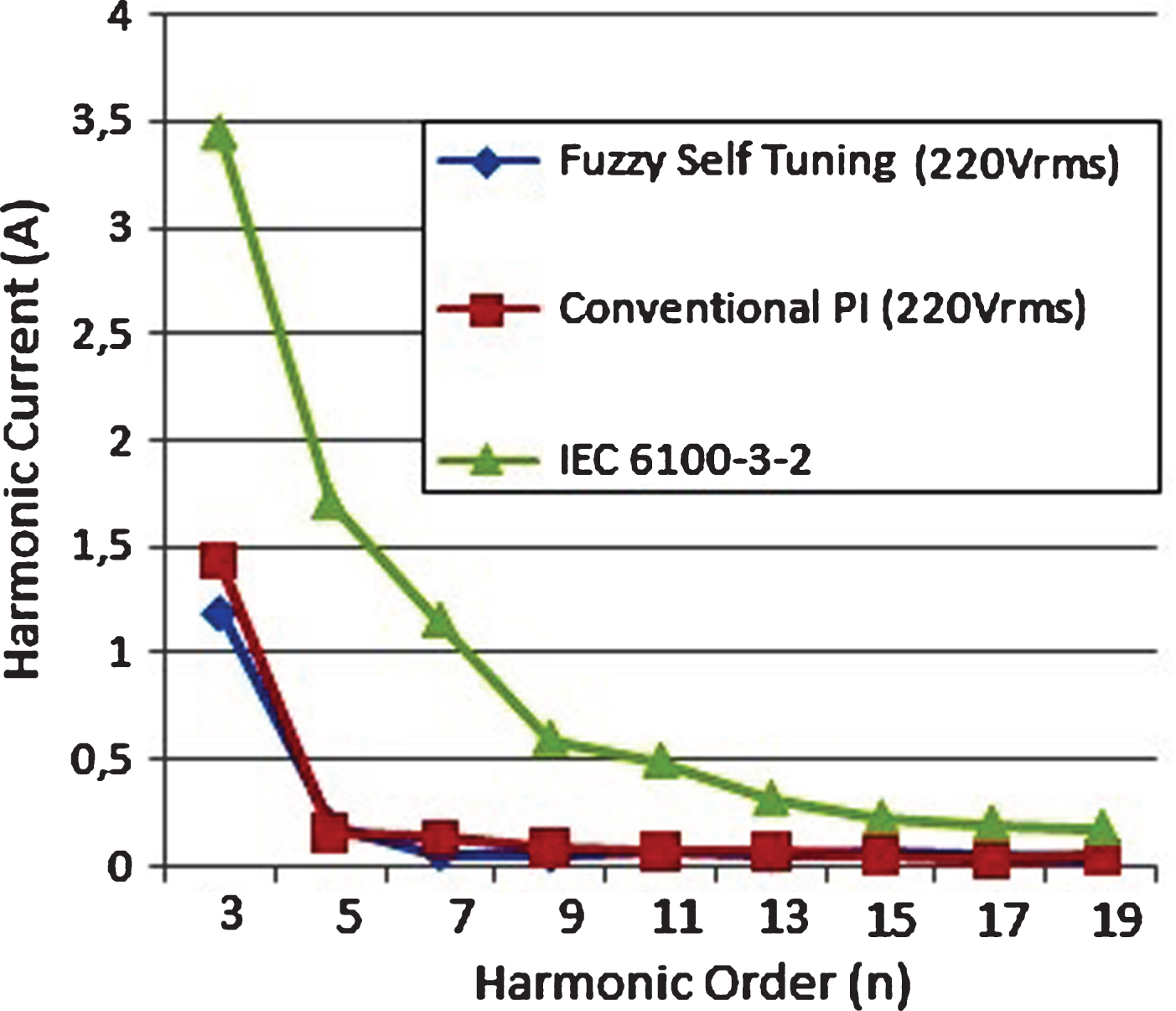
Line current harmonic values of FST and Conventional PI control method compared with IEC 61000-3-2 standard.
From the previous considerations, some of the important advantages and weaknesses of FST control method are given below: This control method satisfies a lower THD of input current and obtains higher UPF, It has a natural way of expressing uncertain systems, It does not need a mathematic model of the system, Flexible control strategies are integrated into FST control method, Due to the its flexible structure, it contains conventional control methods, It uses approximate data, It can deal with nonlinear systems.
It is pointed out that FST control method does not fit to every problem for all case of operations. Its most relevant weaknesses are summarized as follows: The rule tables are not suitable for all applications, these are chosen arbitrarily way and they have different results for each application, There is no systematic approach to FST system designing, It does not have much better characteristics in time domain.
In this paper, the performance of the FST control method applied on bridgeless PFC converter is analyzed to adjust the duty cycles of the converter switches for UPF. FST controller was applied to tune the value of Kp and Ki of the PI controller. Through some tests are done on the system by using input voltage and load variations. The system responses indicate the performance of the bridgeless PFC converter was improved and satisfied compare to conventional PI controller. The feed forward is also used into the control method to improve the converter performance.
The results show the input PF is 0.99 and AC line current THD is nearly 2.5% that can be achieved by using the FST control method. The results for steady state show that the proposed PFC control method can achieve near UPF under wide input voltage and output power changes. Besides, the performance of FST control method is compared with conventional PI controller. Comparing the results obtained from studies show that the FST control method is a robust method and compatible with IEC 61000-3-2 standards. The method and results presented in this paper will be useful for the design switching of PFC converters.