
Abstract
In this paper an adaptive fuzzy variable structure control integrated with a proportional plus derivative control is proposed as a robust solution to the trajectory tracking control problem for a differential wheeled mobile robot under effect of uncertainties and disturbances. To minimize the problems found in practical implementations of the classical variable structure controllers, a single-input single-output adaptive fuzzy logic system replaces the discontinuous portion of the controller. Stability analysis and the convergence of tracking errors considering the adaptive law are guaranteed with basis on the Lyapunov theory. Simulation and experimental results of the proposed control strategy are explored.
Keywords
Introduction
An important control problem for the autonomous robot locomotion is the tracking of a given feasible trajectory parameterized in time with robustness despite of uncertainties and disturbances [1]. Thus, this paper describes the design of a simple and effective robust kinematic controller, for the differential wheeled mobile robot (DWMR) [2], based on the sliding mode theory.
Due to robustness properties against modeling imprecision, uncertainties and disturbances, the variable structure control (VSC) has become very popular and it is used in many application areas [3, 4]. However, this control scheme has important drawbacks that limit its practical applicability, such as chattering and large authority control, which deteriorate the system performance [5–7].
Researches have been developed using softcomputing methodologies, in order to improve the performance and reduce the problem found in practical implementations of VSCs [8]. In this paper, a single-input single-output (SISO) adaptive fuzzy system is proposed and applied to a VSC to avoid the chattering and compensate the uncertainties and disturbances, since it was proven to be a feasible tool to approximate any real continuous nonlinear system to arbitrary accuracy [9]. The proposed fuzzy system, differs from related works [10–18] (with simulation results only) and [19] (with simulation and experimental results) with respect to the control design properly developed, the simple structure using triangular membership functions, and the reduced number of rules to be evaluated, showing lower computational load and feasibility in real-time implementations.
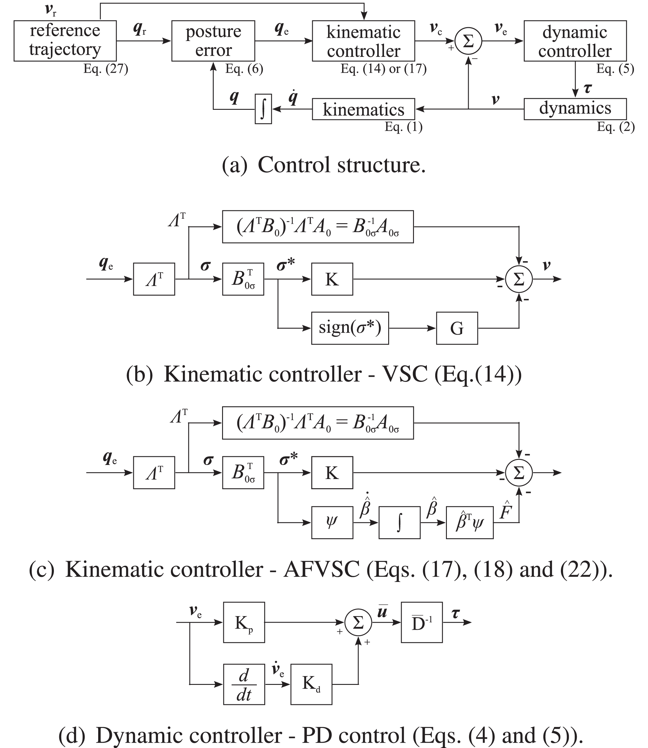
The following studies [20–28], that consider the kinematics of wheeled mobile robots with or without uncertainties and disturbances, also have used the VSC and sliding mode control theories applied in the trajectory tracking control problem of DWMRs, and presented techniques to eliminate chattering phenomenon. Thus, the differences and contributions of this paper are: development of an AFVSC in Cartesian coordinates, based on the sliding mode theory; development of a adaptive fuzzy system to replace the discontinuous portion of the classical VSC, avoiding the chattering as well as suppressing the uncertainties and disturbances without having any a priori knowledge of their limits; stability analysis of the closed-loop control system with the adaptation law of the fuzzy system are proved using the Lyapunov theory; the integration of the kinematic controller (AFVSC) with a dynamic control (PD or Proportional-Derivative control) that must ensure a stable and fast tracking of the references spite of neglected dynamics aiming to improve the robustness against chattering; evaluation of the performance of the VSC and AFVSC, by means of simulations and experiments using Matlab/Simulink, MobileSim simulator and the PowerBot DWMR, over a feasible complex eight-shape trajectory; verification that the loss of invariance has little practical meaning [29] and the robustness is ensured in the case ofthe AFVSC.
Problem formulation
Kinematics and dynamics of DWMRs
A simple model that represents the main kinematics and dynamics of the DWMR is extensively used in literature [26, 31]. Disregarding gravitational forces (
The trajectory tracking control problem for DWMRs [32] is accomplished by proposing a control structure that uses adaptation and fuzzy logic on VSC, to design a robust kinematic controller that avoids chattering and makes the posture tracking errors tend to zero quickly, and a PD control as design of a dynamic controller that makes the auxiliary velocity tracking errors also tend to zero quickly.
Controller design
The problem of mobile robot control can be divided in three ways [33]: control considering only the kinematic model, control considering only the dynamic model and control using both the kinematic and dynamic models. In this paper we focus on controllers based on the utilization of both models (kinematic and dynamic).
Dynamic control
The objective of the dynamic controller is to compensate the known torques and forces described in Equation (2) and ensure fast convergence of the auxiliary velocity tracking errors
The vector
Further, the authors of this work are aware that the VSC or AFVSC could handle the entire control problem without the PD controller, but as the real DWMR that is used as experimental platform (the PowerBot DWMR) has in its firmware this PD controller as a basic and unremovable dynamic control in the architecture (the DWMR can not be direct torque controlled), it has to reflect this architecture in the simulations and to the entire solution.
In literature, the nonholonomic tracking problem could be simplified by considering kinematics sufficient to represent a mobile robot, neglecting the dynamics of the DWMR and considering only the steering system. Moreover, many of these kinematic controllers were developed disregarding robustness. Thus, to compute the control inputs of the DWMR, it is assumed that there is perfect velocity tracking [1, 35]. There are three problems with this approach: first, the perfect velocity tracking assumption does not hold in practice for real situations; second, uncertainties and disturbances in the kinematic and dynamics models are ignored; and, finally, complete knowledge of the dynamics is needed [1, 35]. These problems may compromise the accuracy of the results if the kinematic controllers do not present robustness. In addition, these kinematic control designs become fragile when there is no specific dynamic control system for the actuators or when the dynamic control system for the actuators fails (does not compensates for dynamics, uncertainties and disturbances adequately or satisfactorily). Therefore, when this occurs, the correct behavior of the kinematic controllers is not guaranteed, since the DWMR does not respond instantaneously to the control signals generated and applied to its actuators, due to the dynamics of the DWMR and actuators. Thus, projects of robust kinematic controllers, specifically variable structure controllers, to deal with the problems of the dynamic effects, including the uncertainties and disturbances in the kinematic model, described in rectangular coordinates are treated in this paper. In addition to the justifications reported above for such treatment, it should also be taken into account that most of the dynamic controllers of DWMRs generate torques as a control signal [36], however, commercial DWMRs usually deals with velocity signals and not torques, such as the Pioneer robot from Mobile Robots Inc., Khepera from K-Team Corporation, Merlin Miabot Pro Autonomous Mobile Robot from Merlin Systems Corporation and Soccer Robot from Microrobot [37].
The kinematics of the virtual DWMR is modeled as
Converting the posture tracking errors in the inertial frame to the DWMR frame, the posture error equation of the DWMR can be denoted asin [26]:
Under robustness considerations, in practical situations the velocities and tracking errors are not equal to zero. The best that can be done is to guarantee that the error converges to a neighborhood of the origin. If uncertainties and disturbances (e.g., external disturbances) drive the system away from the convergence compact set, the derivative of the Lyapunov function become negative and the energy of the system decreases uniformly; therefore, the error becomes small again [32].
As perfect velocity tracking does not hold in practice, the dynamic controller generates auxiliary velocity tracking errors
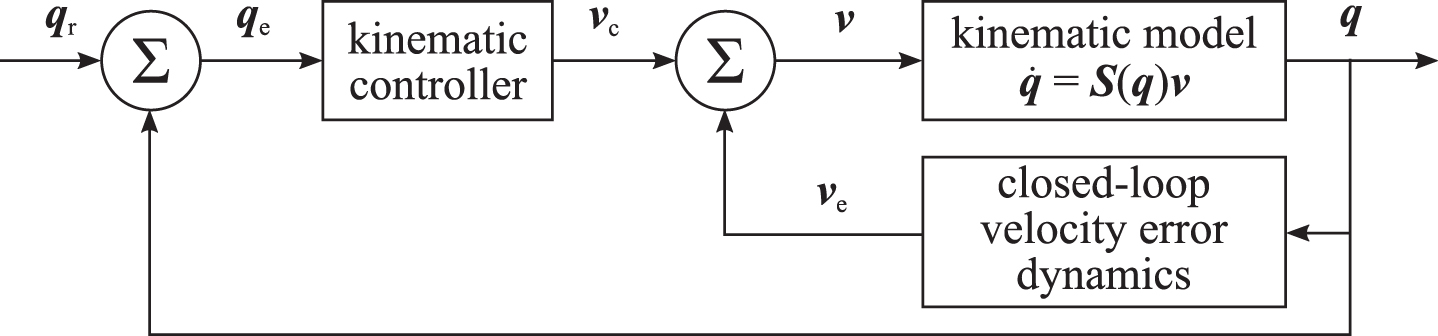
Block diagram of the closed-loop control system: v e as uncertainty and disturbance for the kinematic model (similar to [32]).
The effect of the uncertainties and disturbances (e.g., external disturbances) that affect the system can be considered, after mathematical manipulations, as a term:
To design the kinematic controller, which is based on VSC theory, from the error dynamics, Equation (7), are selected the following sliding surfaces:
After the selection of the sliding surfaces and with basis on the generic modeling of nonlinear systems to the VSC design, the error dynamics in Equation (7) can be rewitten as:
For the stability analysis, it is chosen the Lyapunov function candidate in the form:
Unfortunately, in practical implementation, due to delays, neglected dynamics, sampling frequency limitation, physical limitations of actuators and imperfections of switching, it is not possible to switch the control from a value to another instantaneously [31, 38]. Thus, the state trajectory varies in a vicinity around the sliding surfaces, instead of sliding over it. This phenomenon, known as chattering, can be avoided or at least reduced replacing the discontinuous function sign (
Such approximation can avoid chattering but the invariance principle is not verified anymore, theoretically reducing the robustness (such reduction is not significant and the robustness is ensured). However, the smooth control signal is achieved [26, 38]. This occurs because the system dynamics in this case is continued to a neighborhood of the sliding surfaces, and no longer over it, i.e., as a consequence of the approximation the system is enforced to a neighborhood of the manifolds
In order to get better results without the need of the knowledge of the limits of uncertainties and disturbances in the system, in this section an AFVSC is proposed to deal with the chattering.
Introducing fuzzy systems
A fuzzy logic system can integrate knowledge of an expert into control procedure, without the help of a mathematical model. The four basic parts of a fuzzy logic system, that can be mathematically formulated, are: fuzzification, fuzzy rule base, inference machine, and defuzzification. Further details can be found in [9].
In this paper, the output y of a SISO fuzzy system with M rules considering the input x can be written as:
The chattering in the control law presented in Equation (14) is caused by the constant value of
Defining
Let the Lyapunov function candidate be:
Using the control law (AFVSC), Equation (17), the Equations (19) and (21), and replacing the adaptive law, Equation (22),
From Equation (19), assume that:
The right side of Equation (24)a can be written as
To decide the rules for the fuzzy systems, consider V as in Equation (13). V is regarded as an indicator of the energy of
Because of the function sign ( IF
where (X, m)∈ (NB,1), (NM,2), (NS,3), (ZE,4), (PS,5), (PM,6), (PB,7), N stands for negative, P positive, ZE zero, S small, M medium, andB big.
The membership functions are chosen to be triangular-shaped functions, where
Parameters of the membership functions of σ*
It must be emphasized that the processing time required when using fuzzy logic control depends upon the number of rules that must be evaluated. Moreover, large systems with many rules would require very powerful and fast processors to compute in real-time. The smaller the rule base, the less computational power needed [17]. Thus, unlike a pure fuzzy logic controller which is encountered in the rule expanding problem, the AFVSC, as simplest model, uses only 7 if-then rules in the rule base with respect to sliding surfaces, as well as it uses triangular membership functions, making their structure even simpler and suitable for implementation in real DWMRs. In addition, the reasons to choose this fuzzy inference system with respect to other methods are: to be a simpler model; to control the system efficiently, being best suited for control applications; to be used often due to the intuitive nature of the system and ease in designing. Further details about this choice can be found in [39, 40].
In order to verify the performance of the controllers described in Sections 3 and 4, the VSC, and the AFVSC are implemented in Matlab/Simulink software and evaluated for the trajectory tracking control problem by means of: simulation using the DWMR simplified model proposed on Section 2; DWMR simulator - the MobileSim; and application in the PowerBot DWMR. The Matlab/Simulink executions were performed with the Euler solver for equation integration with sampling time of 5 ms. Other integration methods were tested, but only with marginal improvement. Moreover, these simulations and experiments were carried out in a Intel Core i7-4500U Processor (4M Cache, up to 3.00 GHz), and without any effort for optimizing the code, thence the computation time may be considerable. However, in a real time implementation probably C code, with proper code optimization, would be employed, with much shorter computationtime.
An eight-shape trajectory was used as reference, which is similar to that of [41]. This trajectory is more complex, considering the deceleration and acceleration, with the linear velocity varying between 0.15 m/s and 0.45 m/s and the angular velocity varying between -0.7 rad/s and 0.7 rad/s along the trajectory, as well as it has an initial error
The gains of the sliding surfaces for this trajectory are Λ1 = 1.5, Λ2 = 6.0, Λ3 = 1.0; the gains of the kinematic controllers are g1 = 0.1, g2 = 0.3, kappaup1 = 0.1, kappaup2 = 0.1 for the VSC, and kappaup1 = 0.1, kappaup2 = 0.1 for the AFVSC; and the gains of the dynamic controller (PD controller in [31]) are kpnuup = 40.0, kpomegaup = 40.0, kdnuup = 20.0 and kdomegaup20.0. It is emphasized that gains of the sliding surfaces and the kinematic controllers were obtained through optimization using the design optimization toolbox of Matlab/Simulink and not by trial and error, while the gains of the dynamic controller are provided by the manufacturer of PowerBot DWMR. In addition, the parameter
The PowerBot DWMR has a closed architecture and has implemented a PID controller that tracks the velocity inputs with a sampling time of 5 ms and with the PD parameters specified above. Sufficient analysis results are obtained studying two different control structures comprising the integration of the PD controller (dynamic controller) with the VSC and AFVSC kinematic controllers.
For the performance analysis, it is used the root mean square (RMS) of the errors, being the posture tracking errors given by
In the ideal scenario, the simulations were made in Matlab/Simulink considering the kinematic and dynamic models, (Equation (1) and Equation (2)), that represents the simplified model of the PowerBot DWMR, disregarding uncertainties and disturbances (
Control structure for simulations in the ideal scenario.
In this case, the RMS of the errors obtained from simulation results in ideal scenario were xye = 0.0358, θe = 0.0725 for the VSC, and xye = 0.0382, θe = 0.0828 for the AFVSC.
Figure 3 shows that, using the two controllers, the DWMR gets to the trajectory at a similar point, and keeps on it for the remaining time, i.e., the DWMR satisfactorily follows the reference trajectory. Also, in Fig. 3, the linear and angular velocities of the DWMR present high chattering by using VSC as well as these velocities tend to the reference velocities. Furthermore, for the use of AFVSC, the linear and angular velocities of the DWMR are smooth and do not present chattering as well as it also tends to the reference velocities. Also, the same behaviors have the control linear and angular velocities of both controllers.
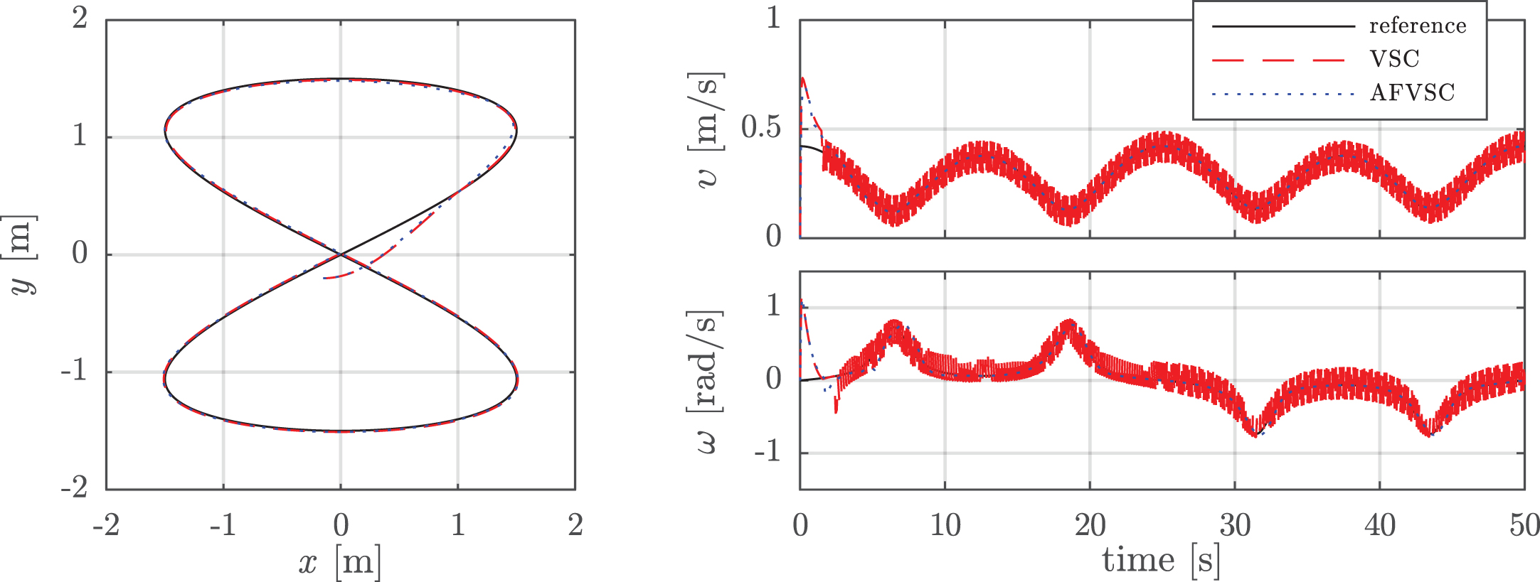
Trajectory tracking, velocities of the DWMR and reference velocities in the ideal scenario for
It is important to emphasize that, under the robustness considerations treated in Subsection 3.2, in the Fig. 4 the auxiliary velocity tracking errors
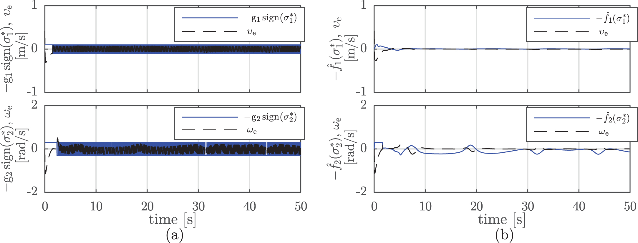
Auxiliary velocity tracking errors and compensations using VSC (a) and AFVSC (b) in the ideal scenario for
In Fig. 5, it is verified that both sliding surfaces (VSC and AFVSC) converge to zero without chattering phenomenon.
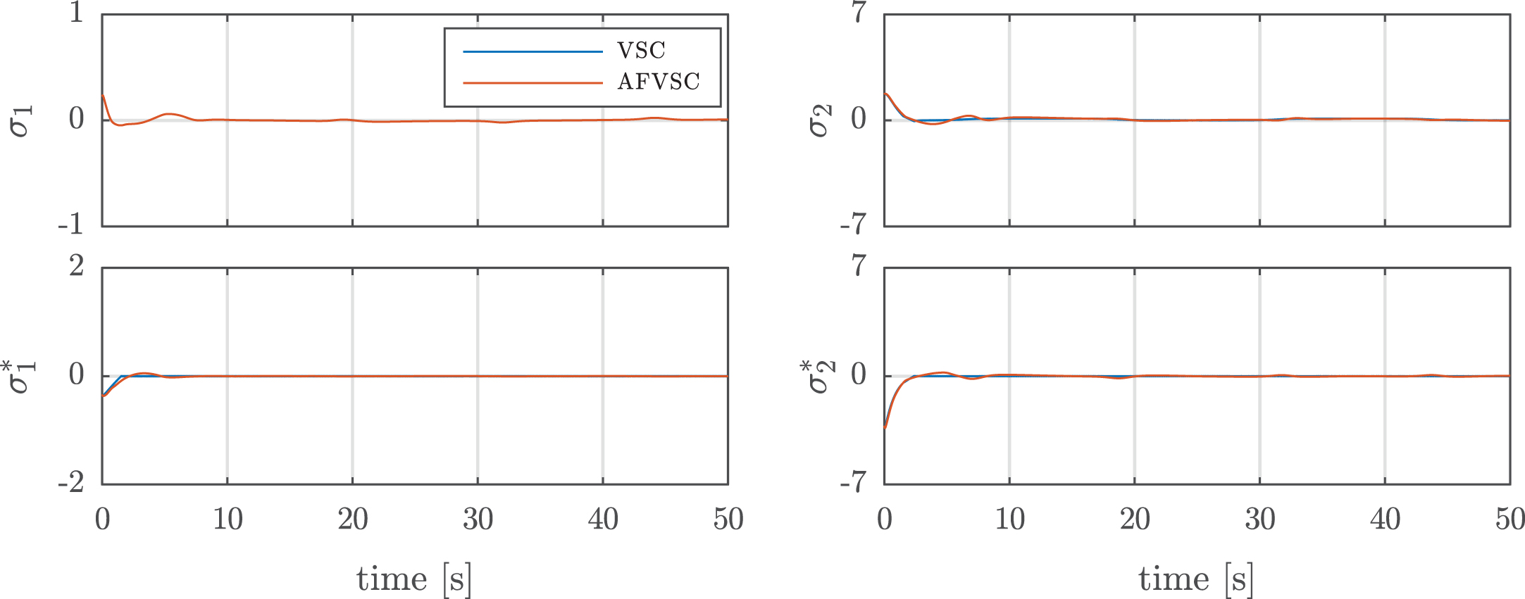
Sliding surfaces σ and new sliding surface σ* in the ideal scenario for
The simulations in the ideal scenario show slightly better tracking results for the VSC at cost of high chattering, recalling that uncertainties and disturbances (e.g., physical limitations, unmodeled dynamics, modeling imprecision and external disturbances, i.e.,
In order to analyze the behavior of the compensator characteristics of kinematic controllers (VSC and AFVSC) under the incidence of uncertainties and disturbances (
In both cases, the disturbances that occur under the kinematic model of the DWMR are provided by the auxiliary velocity tracking errors (Fig. 7), so that the compensation terms of these controllers need to eliminate or compensate such influence. Moreover, the DWMR can perform the trajectory tracking (Fig. 6), consequently the posture tracking errors converge to zero, and both the desired trajectory and the performed by the DWMR tend to be equal. In addition, the sliding surfaces (Fig. 8) and their derivatives, the new sliding surfaces (Fig. 8) and their derivatives, in the sliding mode phase should converge to zero ensuring the robustness of the control. Observing the Figs. 6 to 8, it is verified that AFVSC meets the requirements described above in relation to VSC. Moreover, for this case, the RMS of the errors obtained from simulation results in ideal scenario were xye = 0.1507, θe = 0.1982 for the VSC, and xye = 0.0423, θe = 0.0440 for the AFVSC.

Trajectory tracking, velocities of the DWMR and reference velocities in the ideal scenario for

Auxiliary velocity tracking errors and compensations using VSC (a) and AFVSC (b) in the ideal scenario for

Sliding surfaces σ and new sliding surface σ* in the ideal scenario for
The realistic scenario, instead of using the kinematics Equation (1), dynamics Equation (2) developed to represent the behavior of the PowerBot DWMR and dynamic controller Equation (5) provided by the manufacturer of PowerBot DWMR, is used the MobileSim simulator and ARIA to make the simulations, as presented in Fig. 9. MobileSim is a software designed to simulate the behavior of MobileRobots/ ActivMedia platforms produced by Mobile Robots Inc. for debugging and experimentation. To establish communication between the controller in Matlab/Simulink, and the MobileSim simulator, ARIA is used. ARIA (Advanced Robot Interface for Applications) is a library for all MobileRobots/ActivMedia platforms capable of dynamically control the velocity, heading, relative heading, and other motion parameters of the DWMRs. ARIA also receives position estimation, sonar readings, and all other current operating data sent by the robotic platform.
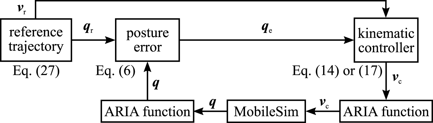
Structure control for simulations in the realistic scenario.
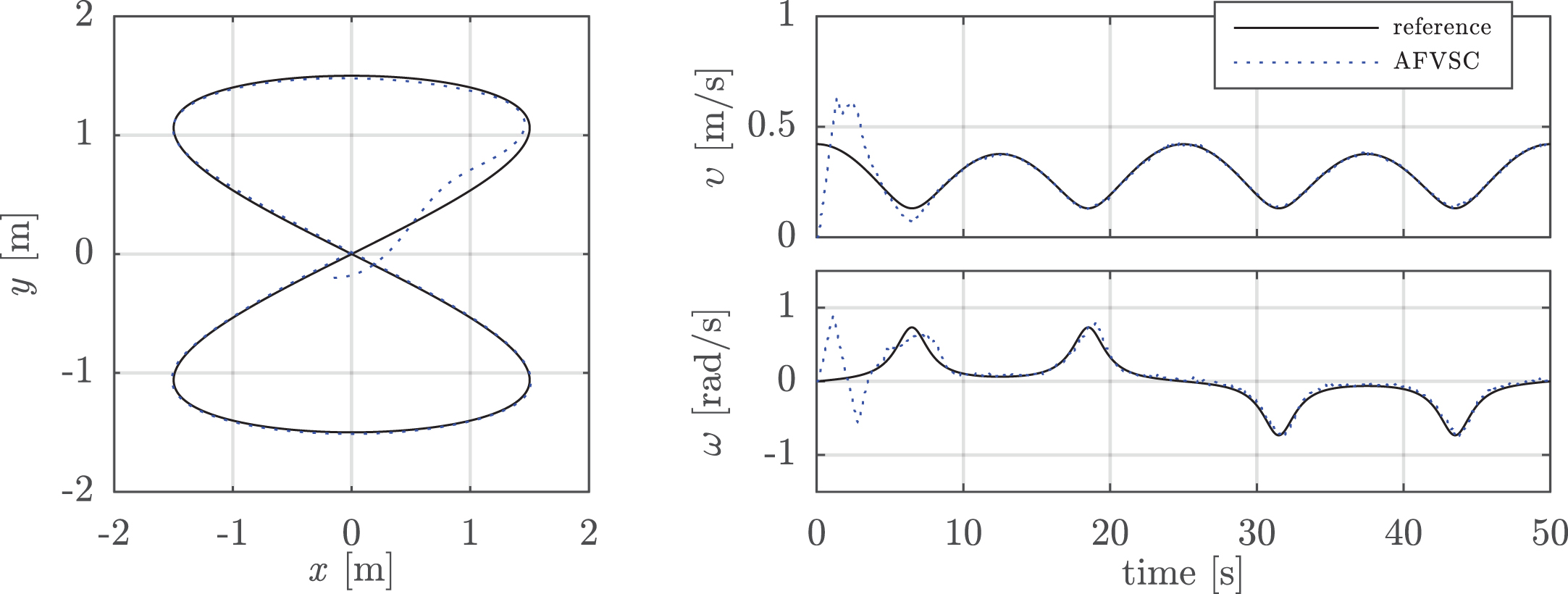
The simulation results in the realistic scenario using MobileSim simulator, whose RMS of the errors were xye = 0.1299, θe = 0.1335 for the VSC, and xye = 0.1252, θe = 0.0940 for the AFVSC, showning that the two controllers can track the trajectory with minumum error even with uncertainties and disturbances considered by the MobileSimsimulator.
The reference trajectory, with respect to realized trajectory by the DWMR using the two controllers, is illustrated in Fig. 10 and it can be verified that the DWMR gets to the trajectory at a similar point and remains near the trajectory during the remaining time, i.e., the DWMR tracks the reference trajectory.

Trajectory tracking, velocities of the DWMR and reference velocities in the realistic scenario.
In the Fig. 10, linear and angular velocities of the DWMR track the reference velocities, being the VSC presents a large chattering, while the AFVSC show smooth control signals. These same behaviors have occurred in the control linear and angular velocities of the two controllers.
Unlike the ideal scenario, in this scenario the Fig. 10 shows how the DWMR can not switch instantaneously the velocities of the DWMR as well as the control velocities, generating large auxiliary velocity tracking errors

Auxiliary velocity tracking errors and compensations using VSC (a) and AFVSC (b) in the realistic scenario.
For the use of the AFVSC, it is verified that the sliding surfaces tend to converge to zero without chattering phenomenon, while for the use of VSC these sliding surfaces present behaviors alternating near zero, as can be in Fig. 12.
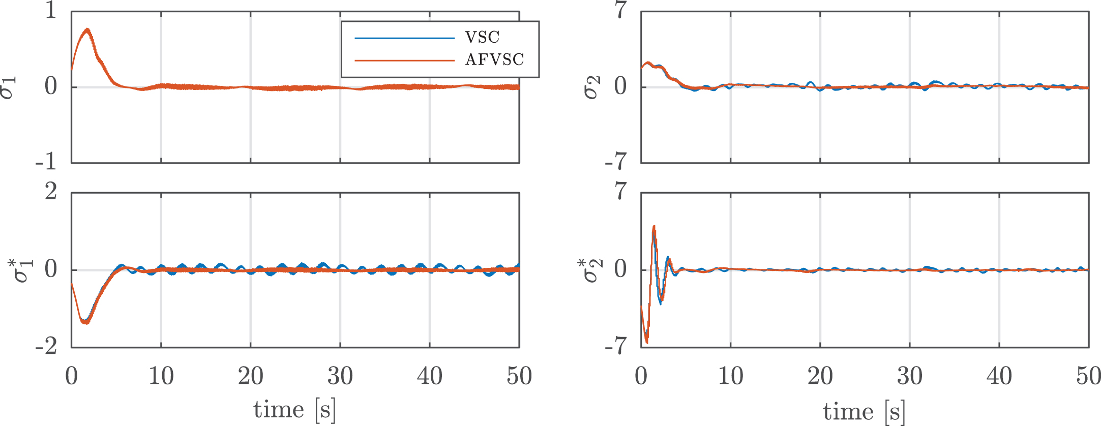
Sliding surfaces σ and new sliding surface σ* in the realistic scenario.
The results show a slightly better tracking performance of the AFVSC when compared to the VSC, recalling that the VSC, as drawbacks, presents high chattering, require the a priori knowledge of the limits of the uncertanties and disturbances to define the gain values
In the experimental scenario, the proposed controller is tested in the PowerBot DWMR to obtain the results. Still, the ARIA is used for the comunication between the Matlab/Simulink and the PowerBot DWMR, which is carried out by a serial port (see Fig. 13). PowerBot DWMR is a high-payload differential drive robotic platform for research and rapid prototyping. It is an ideal platform for laboratory and research tasks involving delivery, navigation and manipulation. It is an automated guided vehicle, specially designed and equipped for autonomous, intelligent delivery and handling of large payloads. Also, PowerBot DWMR is a member of MobileRobots Pioneer family of mobile robots, wich are research and development platforms that share a common architecture, foundation software and emply intelligence based client-server robotics control. The parameters of the PowerBot DWMR provided by the manufacturer are: mass of the body = 120 kg; maximum payload = 100 kg; radius of the drive wheel = 0.135 m; length = 0.9 m; width = 0.66 m; height = 0.48 m; moment of inertia = 15.0656 kg. m2; maximum linear velocity = 2.1 m/s; maximum angular velocity =

Structure control with PowerBot DWMR in the experimental scenario.
It must be emphasized that the practical implementation of VSC was not carried out in the PowerBot DWMR for determining the chattering phenomenon, which causes performance degradation, as well as to verify the occurrence of impossibility of the ideal switching in high frequency required by the control signal, because the switching in high frequency causes reduction in the useful life of the actuators as well as to prevent further damage to PowerBot DWMR.
The AFVSC was tested in the PowerBot DWMR for the eight-shape trajectory and the RMS of the errors obtained in experimental scenario where xye = 0.0892 and θe = 0.1176.
For the AFVSC, Fig. 14 shows how the DWMR reaches the reference trajectory, and holds on it for the remaining time.
Trajectory tracking, velocities of the DWMR and reference velocities in the experimental scenario.
In Fig. 15, by using AFVSC, it is observed how the posture tracking and orientational errors tend to zero and stay there for the remainder of the experiment. The variation of the orientational error has a behavior similar to that obtained during the simulation in MobileSim simulator (realistic scenario).
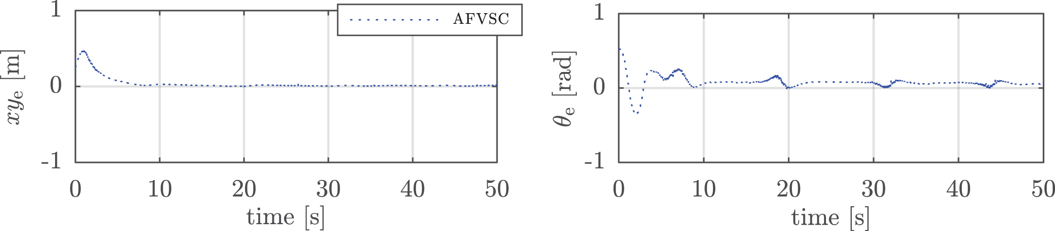
Posture tracking and orientation errors in the experimental scenario.
The control velocities generated by the AFVSC have smooth control signals, as illustrated in Fig. 16. With respect to the velocities of DWMR, it can be observed in Fig. 14 that these velocities track the reference velocities.
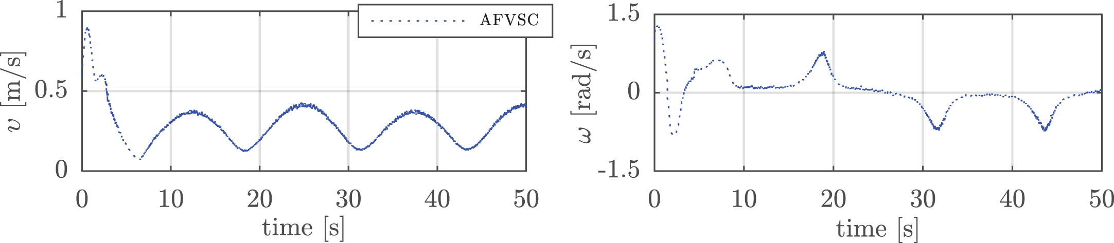
Control velocities in the experimental scenario.
From the observation of Fig. 17, it can be verified that the sliding surfaces and the new sliding surfaces tend to converge to zero and are free from chattering, for the AFVSC.
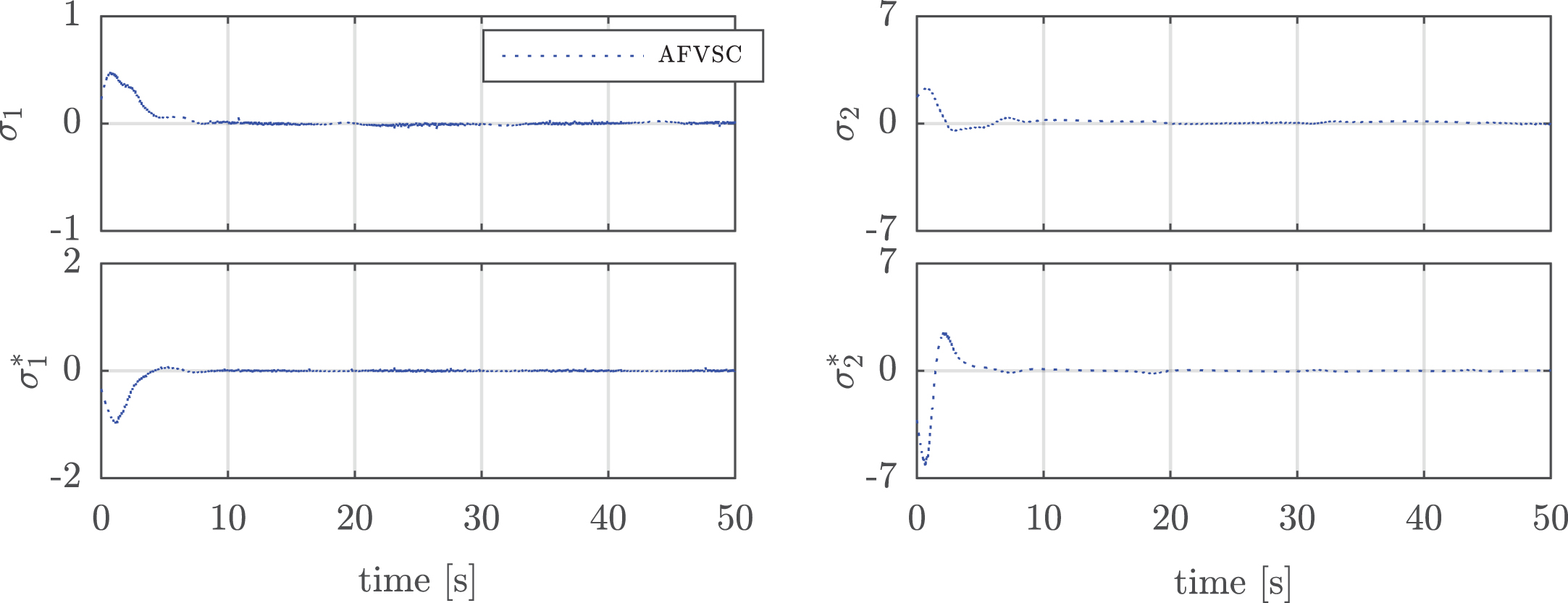
Sliding surfaces σ1, σ2 and the new sliding surfaces
The AFVSC, Fig. 18, present auxiliary velocity tracking errors and compensations, whose magnitudes have opposed behaviors in absolute terms with the aim of annulling or cancelling, i.e., the difference between auxiliary velocity tracking errors and compensations tends to converge to zero. Under the robustness considerations, this tracking error occurs due to uncertainties and disturbances (e.g., parametric variations, unmodeled dynamics and physical limitations), and again the AFVSC demonstrates to be robust to matched uncertainties and disturbances by using function
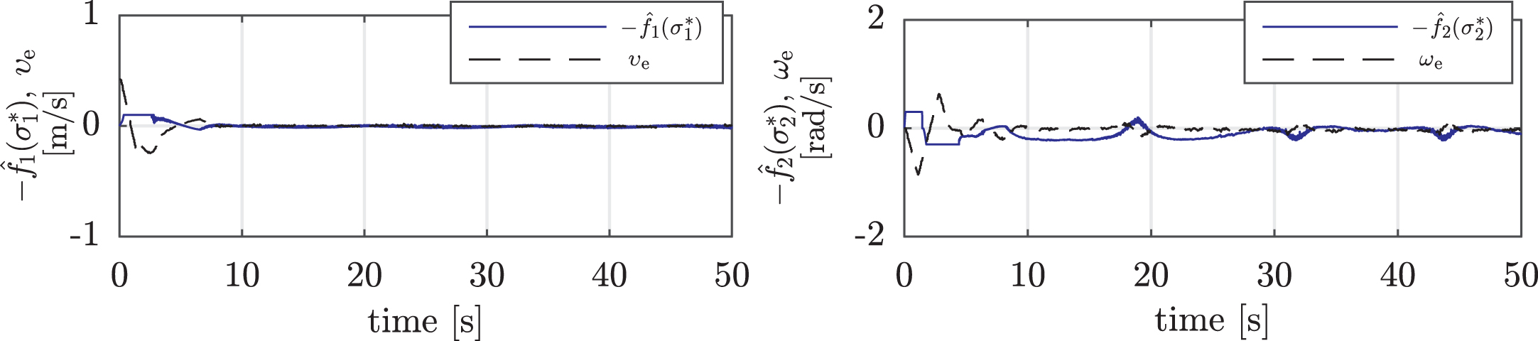
Auxiliary velocity tracking errors and compensations using AFVSC in the experimental scenario.
For the AFVSC, the results in the experimental scenario are coherent with the results obtained in the realistic scenario. Moreover, based on the simulation and experimental results, it is verified that Remark 2.1 provided in [29], i.e., the realization of the invariance requires that switching between the reaching phase and the sliding phase is ideal, which is impractical. Therefore, the invariance is ideal and has little practical meaning.
In this paper, the integration of a kinematic controller (AFVSC) and an dynamic controller (PD control) as a solution to the trajectory tracking problem applied to DWMRs was proposed. For purposes of performance comparison with the AFVSC, a VSC, as a kinematic controller, was also integrated to the PD controller, demonstrating that the incidence of uncertainties and disturbances produces auxiliary velocity tracking errors. The results obtained in realistic and experimental scenarios have shown that: the AFVSC has better performance than the VSC, indicating that the invariance has little practical meaning, the robustness is ensured and a smooth control signal is achieved; the advantages of the AFVSC in comparison to the VSC were verified, making it more suitable for implementation in real wheeled mobile robots when compared to the related works in the literature; the stability analysis of the closed-loop control system with the adaptation law of the fuzzy system were proved using Lyapunovtheory.
In future works, the comparison of AFVSC to other existing chattering reduction approaches (incluing other fuzzy controllers). Another work in progress regards the use of AFVSC in the formation control of DWMRs.