
Abstract
A key radiation sources during the laser-cutting process is sparks, the spark jet angle is closely related to the quality of laser-cutting. A new approach to extract the angle of laser-cut spark jets in industrial metal-cutting processes is presented based on an established machine vision platform. This research demonstrated the algorithm and key theory of PCA and its use in image-processing. The laser-cutting experiment carried out on an St12 steel, the spark images captured during real-time operation are analysed by using the proposed algorithm to obtain the angle and shape of spark jets: the cutting kerf is analysed by optical microscope to acquire the kerf width and associated features. The quantifiable link between sparks angle and kerf width is testified by tests on 1.8-mm thick St12 steel plate, and the results conform to the rules associated with the laser-cutting of metal.
Introduction
Laser-cutting has become the most advanced, and important, material cutting method due to its advantages of high quality, flexibility, and efficiency: it is the most widely used laser processing technology in industry. Laser-cutting accounted for more than 70% of the entire laser processing industry and has developed into a competitive technology [1–3].
With the development of manufacturing and the application of new technology, the shape of parts has become more complex, thus demanding higher cutting quality and imposing more onerous requirements on cutting process parameters. To meet the requirements of material cutting quality, the laser-cutting parameters were limited to within a narrow technological range, and optimisation of cutting processes by traditional manual selection imposed significant limitations, which hindered the application and development of laser-cutting. The different types of light and sound signals generated during laser-cutting can reflect the stability of the cutting process and the quality of the cutting surface [4–7]. By measuring these signals and comparing the signal characteristics under different conditions, the on-line monitoring of laser-cutting quality is possible [8–10]. Therefore, obtaining information about the cutting gap from on-line spark-jets formed during the cutting process, and analysing the characteristic signal corresponding to the optimal cutting quality can help to select optimal cutting parameters. The optimal cutting quality and the highest cutting efficiency were guaranteed under certain technological conditions, which would improve laser-cutting quality and expand the industrial application of the method.
Laser-cutting vision detection is a method used to obtain a cutting-edge vision image directly by CCD and other visual detection equipment. As the method can detect the geometric shape, temperature, and other information in the cutting process, it is a fast-developing research method. Huang et al. developed an intelligent adaptive control system for laser-cutting using photodiodes and CCD cameras, and the light radiation at the incision and conical sparks at the bottom of the incision were monitored by photodiode and CCD camera, respectively. The relationship between the shape of conical sparks and cutting quality was established [11]. Hufflesz measured the cutting edge temperature field on-line by a thermal imager and compared it with the stored optimised cutting temperature field: results indicated that the temperature distribution during cutting was strongly dependent on machining quality [12]. Poprawe established a detection system, and observed the cutting edge by coaxial CCD [13]. In addition, Takashi et al. observed the cutting process by a high-speed camera and studied the cutting edge details and formation mechanism thereof [14, 15].
By analysing the results of cutting edge visual inspection, it can be found that the visual inspection method can obtain more information than the photoelectric tube inspection method, which can measure the cutting gap width, the phosgene coincidence state, changes in surface condition, and laser beam mode information. Roughness detection, when used on a cutting face, can only obtained roughness information about the upper part thereof.
The discharge spark generated in the cutting process originated from the cutting edge and contains abundant information about the cutting edge. The quality of a laser-cut surface could be reflected by photocell sensor detection of the thermal radiation from the spark-jet. Hansmann measured the heat radiation signal at a certain distance from the spark-jet by using a behind-the-cutting-direction device; the signal was focused on the photocell by a convex lens and translated into electrical signals for detection and recording [16]. An Italian team used a CCD device [17, 18] to capture five sets of parameters (jet, its presence, combustion, spraying direction α, width of core injection β, and full injection angle γ) of a spark-jet generated on the back of the cut sheet, and completed the monitoring of cutting quality therewith. The results show that the spray direction α was strongly related to cutting speed and material thickness. The core injection width β was related to the collapse angle at the bottom. The significant difference in the width of core injection β and total injection angle γ indicated a change in cutting parameters. Here, the image of a cutting spark-jet in a laser-cutting sheet was captured by colour industrial camera in real time. According to the characteristics of the spark-jet image, a laser spark angle detection algorithm based on PCA was proposed. Firstly, the colour RGB images were converted into HSV images, and then we extracted the image of the brightness channel. The maximum contour of the spark shower image was obtained by threshold segmentation and the contour direction was calculated by PCA algorithm. The experimental results indicated that the algorithm was efficient and suitable for on-line monitoring of laser-cutting quality.
Laser-cutting spark-jet angle
The cutting edge and spark-jet were two important radiation sources in laser-cutting, which were related to the temperature of the bottom edge of the cutting surface. Due to the high temperature at the cutting edge and thermal radiation interference, it was necessary to study the spark-jet behaviour independently. As shown in Fig. 1, the lower edge of cutting surface was taken as the physical boundary in the laser-cutting process (the upper part of the boundary was the melting layer, and the lower part was the spark-jet). Under the effect of air flow and gravity, the molten metal and its oxides lost the physical support of the cutting edge and formed a spark-jet.
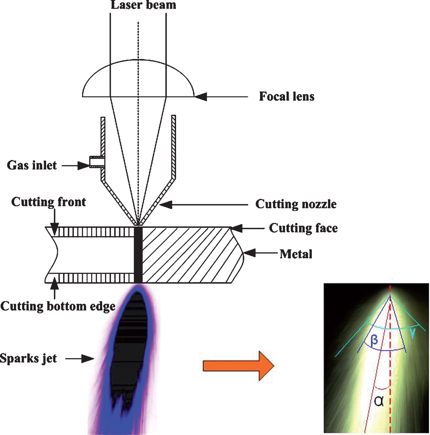
Radiation sources in the laser-cutting process.
Laser-cutting quality and spark-jet angles vary with cutting speed, therefore, obtaining the parameters of laser-cutting spark-jet angle can allow real-time monitoring of cutting quality. As shown in Fig. 1, the laser-cutting sparks angle parameters mainly contained spark jet deflection angle α (strongly correlated with cutting speed and material thickness), and core jet width angle β (strongly correlated with bottom collapse angle): the difference in maximum jet angle γ and core jet width β indicated that the cutting parameters were changing. To obtain quantitative data, α was defined as the angle between the spark-jet centreline and the vertical, and the forward inclination angle was positive (pointing to the uncut part of the workpiece), and the backward inclination angle was negative.
Image acquisition
To avoid interference from thermal radiation at the cutting front, as shown in Fig. 2, a spark shower side detection system was established.
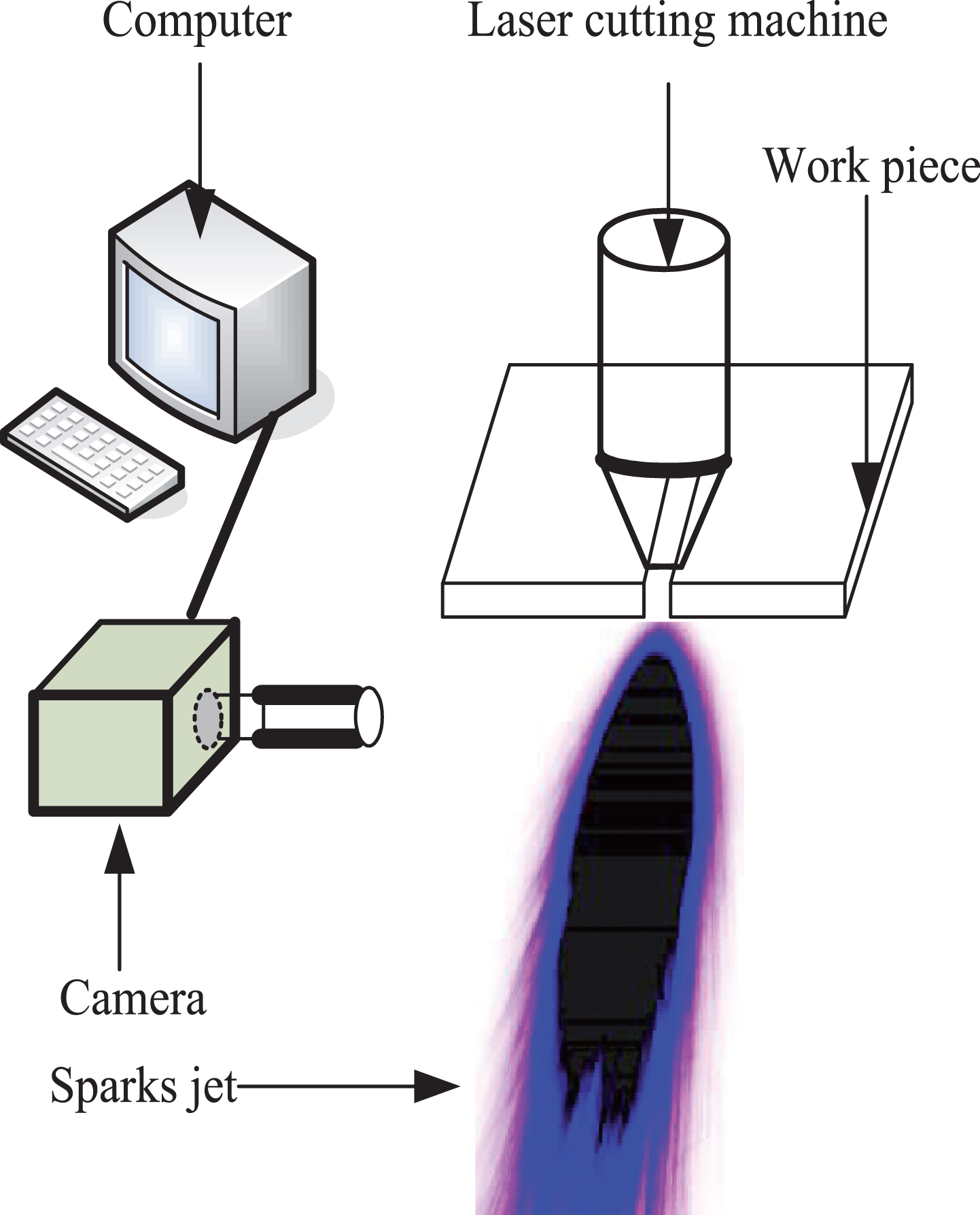
Laser-cutting sparks: real-time detection.
The CO2 laser focused on the upper surface of the workpiece and the CMOS camera was placed on the side of the workpiece. The main axis of the lens was perpendicular to the plane determined by the laser beam and the direction of cutting, and was slightly lower than the cutting surface.
Meanwhile, the cutting front edge radiation is blocked by the cutting surface, and the spark radiation reaches the CMOS camera through the filter. The aperture and exposure time were adjusted to keep the camera image unsaturated, and the optical parameters fixed, throughout the experiment. A spark radiation image free from cutting edge interference can be obtained by this device.
The purpose of PCA [19] is to define an optimised characteristic sub-space so that the observed data can be projected under this sub-space and the components of the maximum variance can be obtained, in other words, to find an orthogonal transformation matrix W that makes the new components uncorrelated with each other after orthogonal transformation of multi-dimensional data. If an n- dimensional random vector X is X is (x1, x2, . . . , x
n
)
T
, its average can be expressed as:
The components obtained by processing with PCA can be expressed as

Principal component diagram of two-dimensional random data.
In fact, a few principal components are enough to express the data information, and the principal component Y = (y1, y2, …, y p ) can be get only if p in the orthogonal transformation matrix W is (w1, w2, . . . , w p ) is less than or equal to n in the orthogonal transformation vector {wi|i = 1, 2, . . . n}. After PCA processing, although only a few independent principal components are obtained, the main information of the data is retained, and data compression and the removal of second-order redundant data are realised.
The covariance matrix C - E [XX T ] is usually a positive definite matrix for natural data, and there must be singular value decomposition C = UVU T , where U is the orthogonal matrix composed of the eigenvectors of the covariance matrix, and V = diag (λ1, λ2, . . . , λ n ) is the diagonal matrix composed of the eigenvalues corresponding to the eigenvectors.
The projection of the observed data in the direction of the optimal projection matrix of PCA composed of the basis vectors of U constitutes non-correlated data and the variance of each component is equal to the corresponding eigenvalue when the eigenvalue satisfies V = (λ1 > λ2 > . . . λ
n
). The minimum mean square deviation of the reconstructed data can be expressed as
Image feature extraction is shown in Fig. 4.
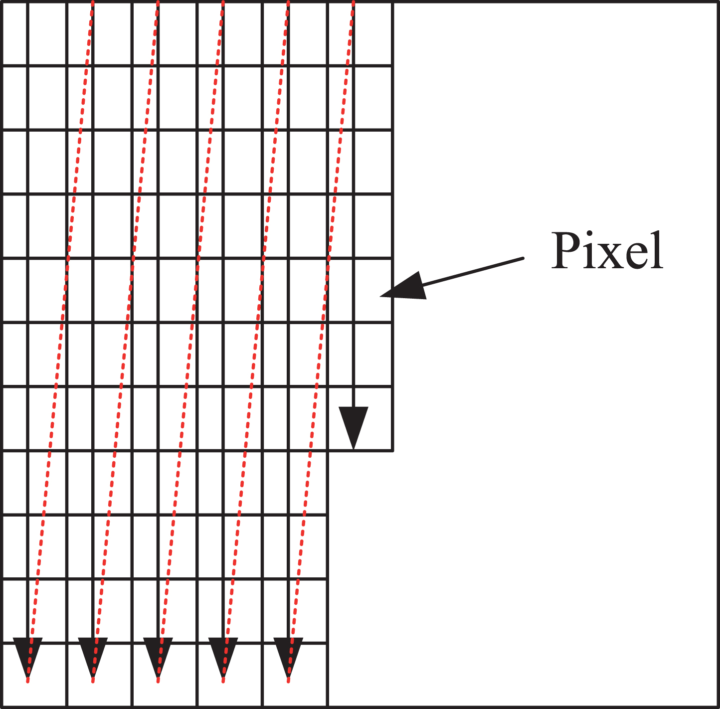
Vectorisation diagram of image matrix.
First, the image needs to be vectorised. Then, the pixels of the image f (x, y) with size m×n are connected from head to tail to compose vector χ. It is assumed that the number of training samples in image training set is M, which is vectorised to get {
χ
i
|i = 1, 2 . . . , M} and the average vector of M images is
Then the covariance matrix of the training image set can be expressed as:
Since the size of XX
T
is mn × mn, for example, the image size is 112×92, the high dimension of XX
T
makes the calculation of the characteristic vector of the covariance matrix complicated, while the size of X
T
X is M × N, usually the number of samples is less than 1000. It is supposed that λ and η is an eigenvalue and corresponding eigenvector of XX
T
, then X
T
X η = λη, and multiplying by X on both sides of the equation gives
The algorithm steps of PCA are summarized by the example of m × n dimension data as follows: Matrix X of n rows m columns is obtained by arranging the original data in columns. The zero mean of X each row is done by subtracting the mean of this row. Calculation of the covariance matrix Calculation the eigenvalue and eigenvector of covariance matrix The eigenvectors are arranged into matrices from big to small according to the corresponding eigenvalues, and the first k rows are taken to form matrix P. The data are transformed into k -dimensional data.
The angle of laser-cutting sparks jet is related to the laser-cutting process parameters, which are closely related to the quality of laser-cutting plate. To establish the quantitative link between laser-cutting quality and laser-cutting sparks, it is necessary to obtain the quantitative angle parameters of laser-cutting. The steps in the angle vision detection algorithm are shown in Fig. 5. Image of laser-cutting sparks captured by CMOS camera with optical filter input the computer by using kilo-mega bps ethernet interface. The original images are pre-processed by Gaussian filter to weaken the effect of noise, light, and contrast. The colour field is transformed the BGR image into HSV image, thus highlighting the brightness channel. The HSV colour space model [20, 21] defines colours on the basis of Hue, Saturation, and Value. H, S, and V are three components of the HSV model and are mutually independent, in which H represents the position of a colour on the visible light spectrum and is measured by an angle from 0° to 360°, S denotes the purity of a colour and its value ranges from 0 to 1, and V denotes the brightness of a colour and its value ranges from 0 to 1. To simplify the operation, OpenCV (open source computer vision library) has transformed the three components to the following formula, in which H0, S0, and V0 represent the original value of the image in HSV space and H1, S1, and V1 represent the values after conversion. The brightness channel (V channel) of HSV image processed by Step 3 is extracted because the V channel is most obvious spark-jet characteristic. By threshold segmentation, the image whose α is strongly correlated with cutting speed is obtained. Estimating whether the maximum contour of the image is obtained: if the answer is yes, the algorithm will go to Step 7, if not, it will return to Step 1, input the image again and continue the process. The PCA algorithm was run to obtain the direction of the maximum contour. The angle calculated by the result from Step 7 is output. Is the image the last one? If so, go to Step 10, if not, return to Step 1 and continue the process. Display angle results End.

Laser-cutting spark-jet angle detection algorithm.
Experimental data description
The experimental CO2 laser-cutting machine (laser power, 1 kW) was defocussed by 2.5 mm, cut the 1.8 mm thickness of the St12 steel plate under oxygen at 0.6 MPa at a rate that changed from 70 mm/s to 130 mm/s. The laser sparks were captured by CMOS camera MV-EM500M/C with a pixel size of 2.2 um×2.2 um at a frame rate of 15 fps. The lens was a type-AFT-1614MP and its focal length was 16 mm. Image data were acquired and processed on a hardware system based on a ThinkPad T470p computer (CPU, Intel®Core™ i7-7700HQ with eight core-processors and 8 Gb RAM). The chosen operating system was MS-Windows 10 (64-bit architecture). Cutting experiments and experimental results are shown in Fig. 6 in which the numbers labelling the workpiece from 1 to 7 are the laser kerf corresponding to laser-cutting speeds from 70 mm/s to 130 mm/s.

St12 experimental steel plate, (a) Laser-cutting steel plate process (b) Back kerf of laser-cutting steel plate.
The machine vision detection algorithm for laser-cutting spark jet angle is testified in two aspects that are algorithm accuracy and applicability verification during the process of laser-cutting metal.
Algorithm accuracy verification
The laser-cutting spark-jet images were acquired using the experimental platform (Fig. 2) and input into the algorithm as original data: Fig. 7 shows the results thereof. The spark-jet angle changed with the cutting speed (the yellow line indicates the direction of the spark-jet, the blue line indicates specific angle data).
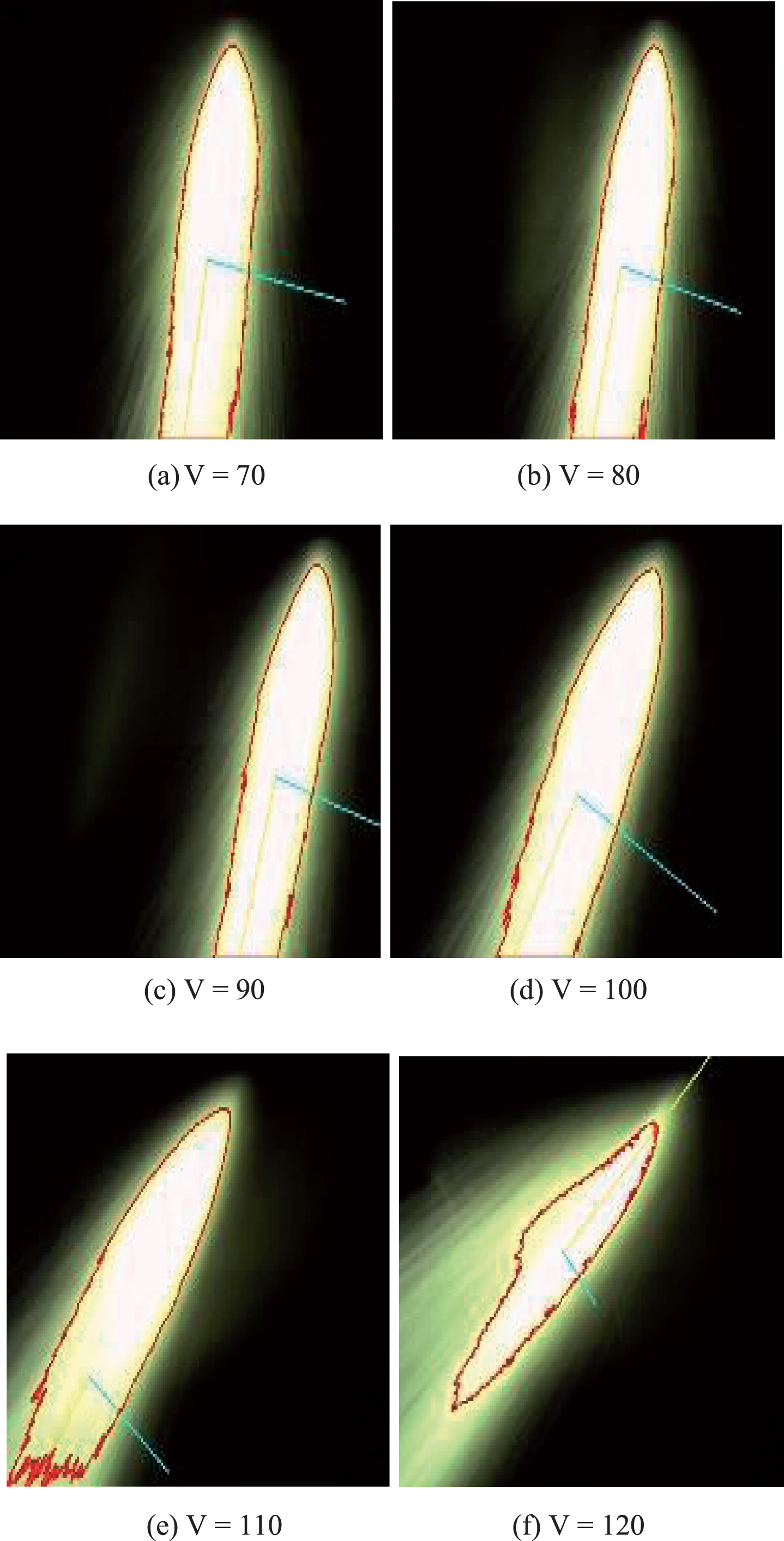
Algorithm-processed images of laser-cutting spark-jet angle (a) Laser-cutting steel plate process, (b) Back kerf of laser-cutting steel plate, (a) V=70 (b) V = 80, (c) V = 90 (d) V = 100, (e) V = 110 (f) V = 120.
The specific angle data acquired by the algorithm and measured by protractor are shown in Table 1.
Angles of laser-cutting spark-jets at different cutting speeds
Figure 8 compares calculated and measured spark-jet angles. The root mean squre error (RMSE) [22] is used to evaluate the pricision of the algorithm:
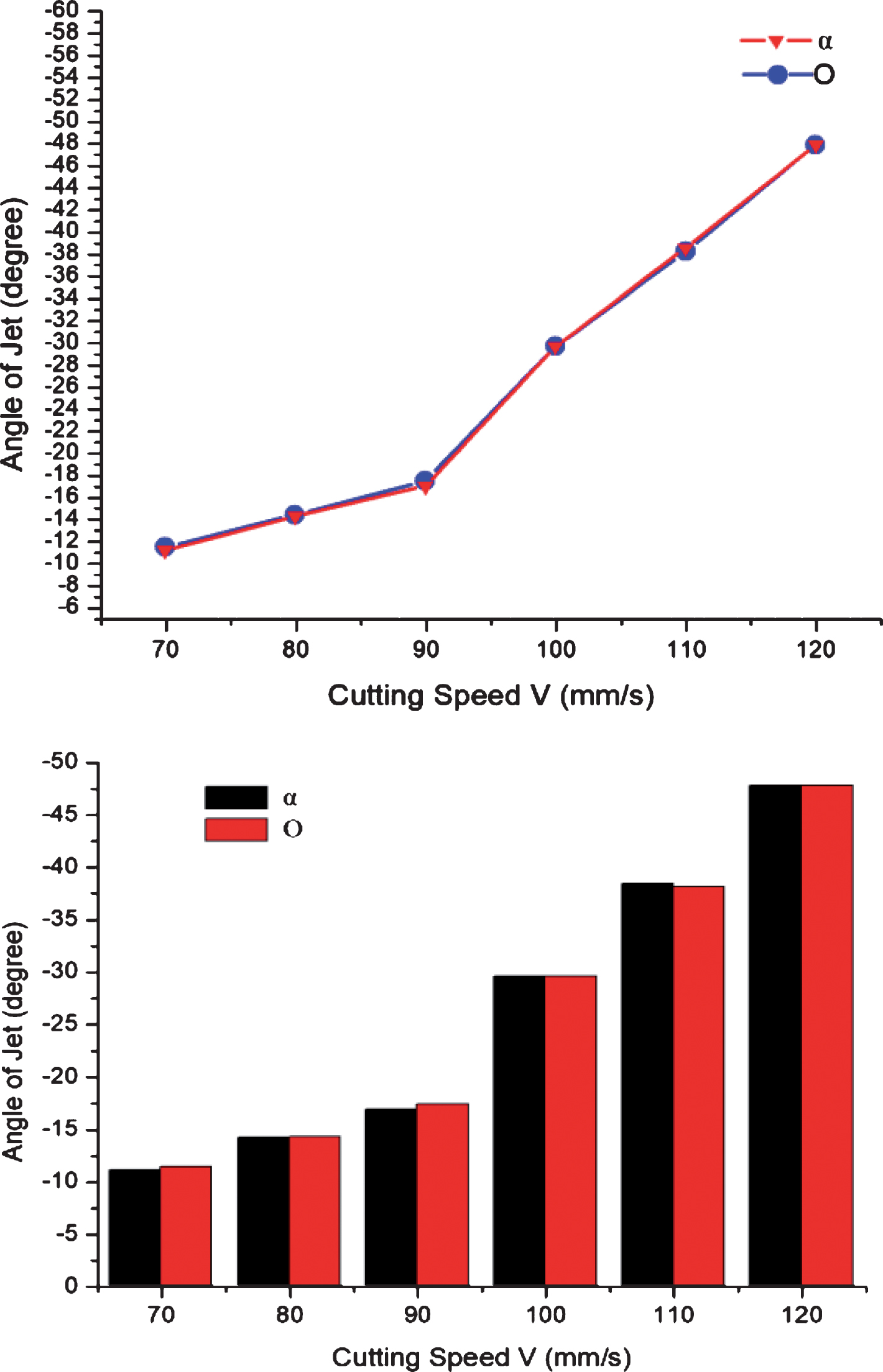
Calculated, and measured, data.
Kerf width at different laser-cutting speeds
One of the important evaluation indicators is laser-cutting kerf width size, and the metal kerf width changes with the speed of laser-cutting, in addition, laser-cutting spark-jet angle also changes with the speed of laser-cutting, so the link between the laser cut quality and laser spark-jet parameters can be found through trial laser-cutting runs to optimise the process and predict the final cutting quality. We used a microscope to observe a sample cut at 70 mm/s (kerf widths are shown in Fig. 9). Figure 9(a) shows the top edge of the cut metal and Fig. 9(b) shows the bottom edge. The kerf widths at different cutting speeds were measured by microscope and are listed in Table 2.
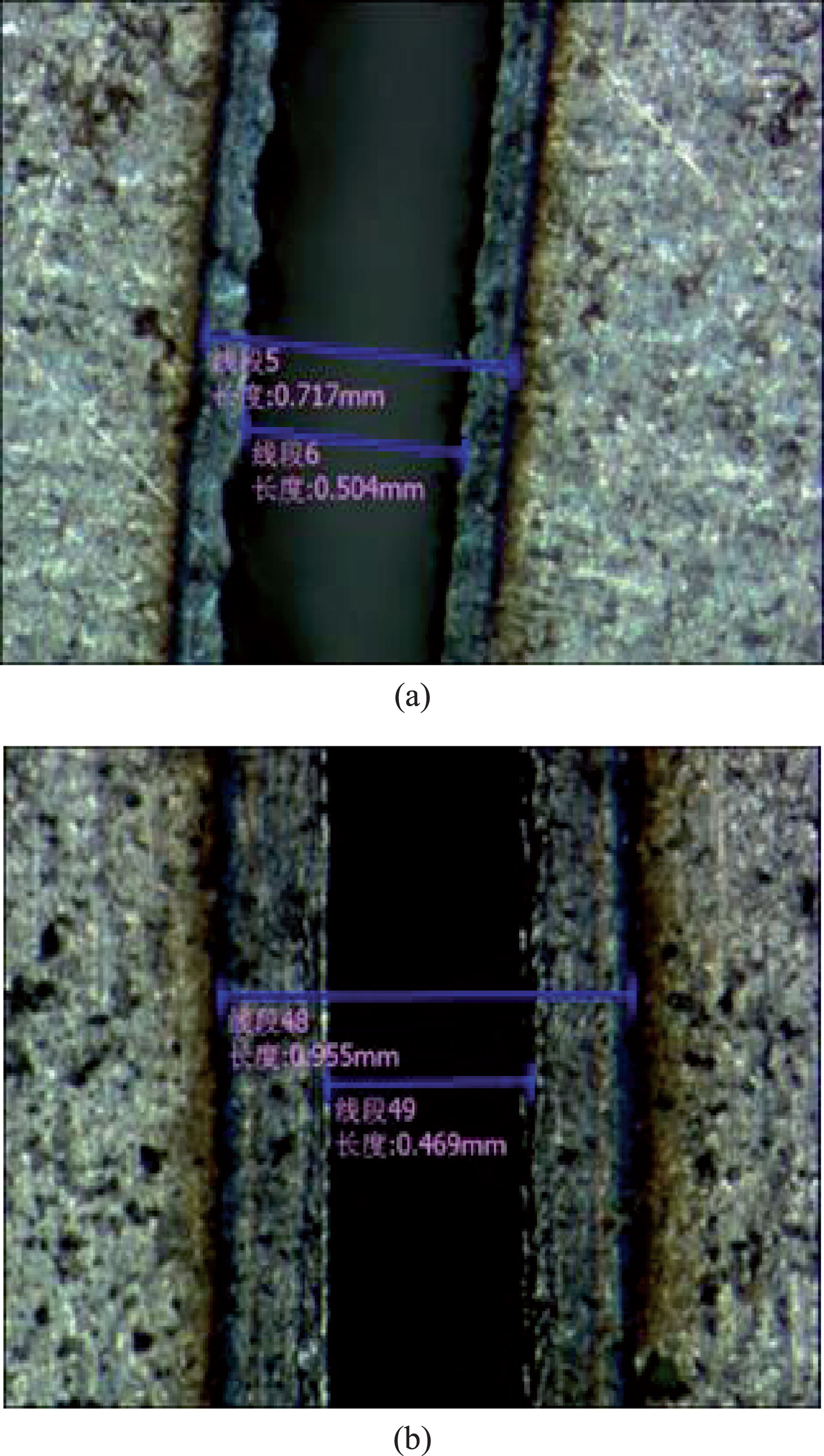
Microscopic image of sample kerf.
The relationship between kerf width and laser spark-jet angle can be deduced (Fig. 10).
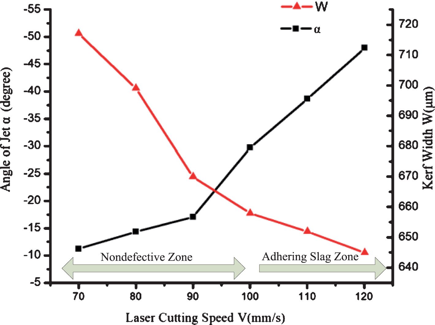
Spark-jet angle v. kerf width at different cutting speeds.
When the laser-cutting process parameters were set, the spark-jet angle α increased, but the kerf width decreased with increasing laser-cutting speed, a finding consistent with known laser-cutting behaviours. The reason for this was that, at faster cutting speeds, the coupling of the metal plate and laser energy in the cutting area was weakened, the heat input reduced, the amount of molten metal decreased, and the width of the cutting kerf decreased. When the cutting speed was too fast, the metal cutting kerf at the bottom edge produced slag and could not be cut due to dissipation of heat energy therein (this occurred here at laser-cutting speeds greater than 100 mm/s).
The conclusions derived from the present experiment are listed as follows: first there was a corresponding relationship between the laser machine cutting quality (kerf width) and the angle of the laser-cutting spark-jet, at the same time the algorithm was shown to be accurate when measuring laser-cutting spark-jets. Secondly, the accuracy of angles calculated by the proposed algorithm allowed us to garner critical kerf-related information from the laser-spark jets, and furthermore, optimise the laser-cutting parameters.
We presented a machine vison algorithm for laser-cutting spark-jet angle analysis and measurement. The combination of Principal Component Analysis and OpenCV allows the algorithm to achieve good accuracy and offer real-time performance. The angle-extraction algorithm was tested by using Visual C++on a multi-core processor system (IntelCore i7) and cross-validation evinced its excellent accuracy. Experiments involving measurement of laser-cutting quality and spark-jet angle were performed: the proposed algorithm was used to establish a quantifiable link between spark-jet angle and laser-cutting kerf quality. The link was not intuitive, however, a mathematical model of laser cut kerf quality, as evaluated by spark-jet angle will be established: the quality information pertaining to a given laser cut can automatically be acquired from its spark-jet angle and cutting parameters can be optimised with a view to automation in future research.
Conflict of interest statement
The authors declare no conflict of interest. There is no professional or other personal interest of any nature or kind in any product, service or company that could be construed as influencing the position presented in the manuscript entitled “A machine vision detection algorithm for laser-cutting spark jet angle”.
Footnotes
Acknowledgment
This work is supported by the Large Engineering Equipment Detection and Controlling Key Construction Laboratory Opening Project of Jiangsu Province, China(No.JSKLEDC201311), and Xu Zhou Sci-tech Plan Project, China(No. KH17011).This research was also supported by China Xuzhou Yiyang electrical equipment co. LTD.