
Abstract
To solve the problem of harmonic distortion generated by the output AC of inverters without considering the relationship between carrier switching frequency and carrier frequency, by analyzing the influence of carrier switching frequency on random carrier signal, it was concluded that the phase mismatch between the front and back carriers was the fundamental reason for the distortion of the output voltage of inverters when the preset carrier was switched randomly. And the switching frequency was randomized by switching the preset carrier, i.e., an improved kind of random carrier frequency modulation (RCFM). The simulation and experimental results showed that the proposed random PWM method could not only suppress the high-order harmonics of the output voltage more effectively, but also have better sinusoidal waveform than the conventional random PWM method.
Introduction
With the continuous emergence of high-speed switching devices, pulse width modulation (PWM) technology had been widely used in power electronic equipment. In the general PWM method, the power switch of the inverter was turned on and off in a “certain” manner. Although this control mode could well suppress the lower harmonic in the output waveform, it was not possible to suppress those higher harmonics related to the switching frequency, which might cause problems such as electromagnetic interference (EMI) and mechanical vibration [1–4]. In addition, the noise of the motor system powered by the PWM inverter was 5–15 dB higher than the noise in direct power supply of power grid, which greatly affected the quality and working environment of motor products, therefore, reducing the audio noise of inverter-fed motor was an important issue that people pay close attention to at present. Although the noise reduction could be achieved by increasing the switching frequency to above 20 kHz to avoid the sensitive range of human hearing [5], increasing switching frequency would increase switching loss of power devices and bring adverse effects on heat dissipation of devices. Another solution was to add a primary filter between the inverter and the motor, which obviously increased hardware costs and also reduced the efficiency of the motor drive system.
In order to solve the problem of electromagnetic compatibility and noise pollution of inverter, American scholar Trzynadlowski A. M. proposed a new PWM technology, i.e., random pulse width modulation [6]. The random pulse width modulation technique was to make the original periodic switching signal become non-periodic signal by adding random signals distributed according to a certain probability law to switching signals and to distribute the energy concentrated on the switching frequency and its harmonic frequency in the whole frequency domain, so as to reduce the amplitude of discrete harmonics and to make the power density spectrum show continuous spectrum characteristics, which suppressed high-frequency noise and conducting EMI existing in power switching circuits [7–9]. In addition, random pulse width modulation (RPWM) did not need to change the topology of the main circuit of the system, so its appearance provided an economical and effective solution to the problems of audio noise and electromagnetic compatibility of inverters [9]. And then we used a random method of switching preset carrier, i.e., an improved kind of random carrier frequency modulation (RCFM), to realize randomization of switching frequency and carried out simulation and experimental analysis.
Basic principle of random pulse width modulation
It was well known that the essence of PWM was the control of the duty cycle, which was determined by the ratio of the on time of the switch to the switching period. For the traditional deterministic pulse width modulation, the pulse width, pulse position and switching frequency remained unchanged. The key of random pulse width modulation (RPWM) was to change the on and off time of the switch randomly without changing the duty ratio or the average duty ratio, so that the switching action of the power device becomes uncertain.
Figure 1 showed the definition of the modulation function Fm (t) and three modulation parameters (Tk, ɛk, αk) for controlling the switching device of the power converter. In principle, these three modulation parameters could be changed randomly, i.e., the frequency and position of the pulse within a switching period were independently variable, and the pulse width was also variable under the constraint condition. However, the duty ratio αk determined the output voltage of the converter, and for DC/DC converters, the αk should remain relatively constant if a stable DC output voltage was to be obtained. For DC/AC converters, αk should vary sinusoidally over a fundamental period. In general, the duty ratio αk could not be changed arbitrarily. Therefore, in random pulse width modulation, only two modulation parameters of the switching period Tk and the pulse delay coefficient ɛk could be changed independently at a random rate [11].

Random PWM modulation function and parameter definition.
At present, there are three kinds of random pulse width modulation methods, i.e., random pulse width modulation (RPWM) [6], random pulse position modulation (RPPM) [12] and random carrier frequency modulation (RCFM) [13]. And RCFM had the best ability to weaken the higher order harmonic, and it produced the lowest order among the three methods [14], so RCFM was the most widely used random pulse width modulation method
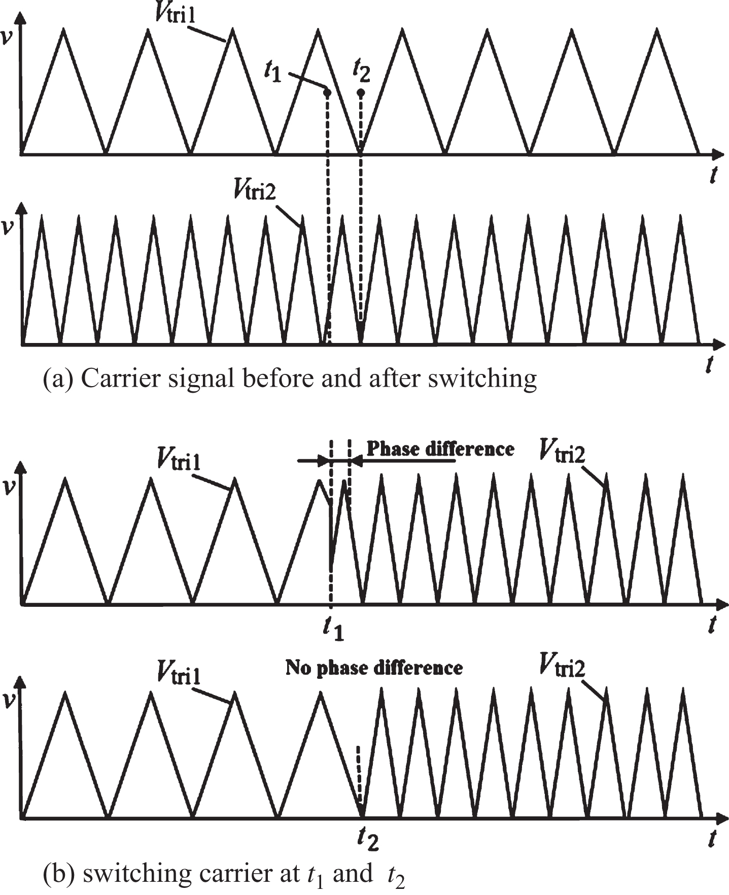
Random sequences generated by RCFM method in existing literature [7, 15] contained relatively large and uncertain values [16, 17]. Although these values were switched at a fixed frequency (clock signal frequency), there was no correlation between the two random numbers before and after switching, and correspondingly there was no relationship between the two carrier frequencies before and after the switching. For convenience of description, this kind of randomization method was called carrier numerical randomization. The effect of clock signal frequency on carrier switching was shown in Fig. 2.
Influence of clock signal frequency on carrier switching.
From Fig. 2, it could be found that if the carriers were switched at time t1, the phases of the front and back two carriers (Vtri1 and Vtri2) were not synchronized, therefore, the phase convergence error would appear before and after the switching of the two sine pulse sequences. In contrast, the two carriers were in a phase synchronization state at time t2, so that switching the carrier at that time did not produce a phase difference, and there was no waveform distortion. In short, the frequency of the clock signal (carrier switching frequency) and the frequencies of the two carriers before and after switching must meet a certain relationship to avoid the above problems.
Overall programme
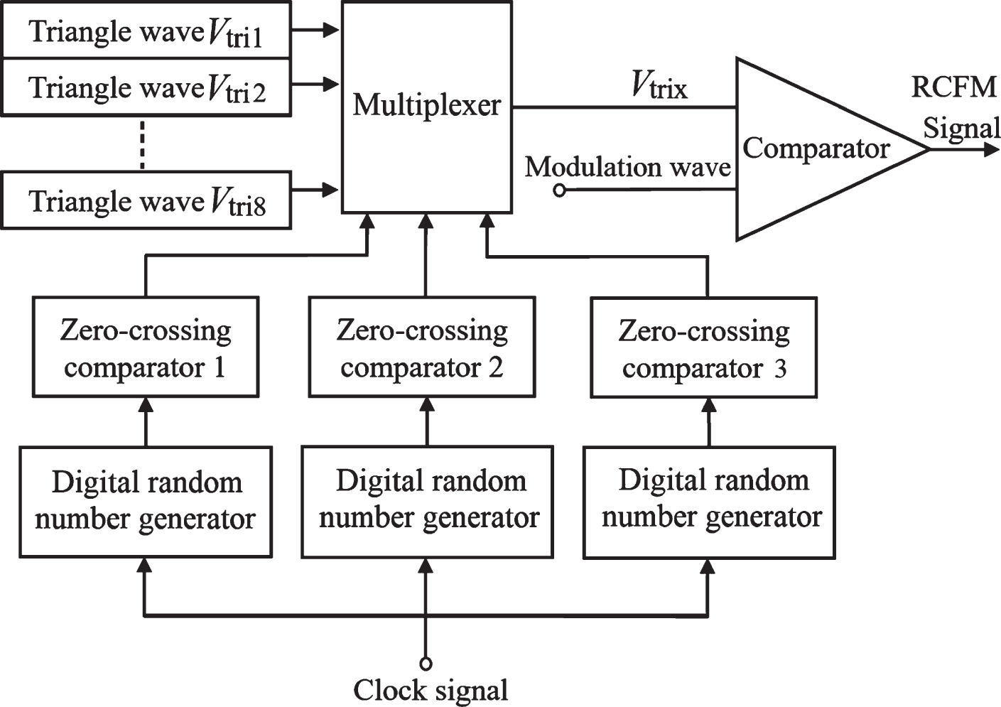
Since the relationship between the carrier frequency and the clock signal frequency needed to be satisfied certain relationship to avoid the aforementioned phase convergence error, this paper proposed a method based on the preset carrier to realize the randomization of the switching frequency (RCFM). The implementation principle of this method was shown in Fig. 3.
Implementation principle of RCFM method based on preset carrier wave.
It could be seen from Fig. 3 that several carrier signals of different frequencies were set in advance and then connected to a multiplexer whose gating logic is a random signal generated by a digital controller. It should be noted that the random number generated by the random number generator could be either positive or negative, so that its probability of generating positive or negative random numbers was random. Comparing the random number (actually random positive or negative potential) with a zero-crossing comparator, the results of the comparison, i.e., the “ 0” and “ 1” states, were also random. The random result output by the comparator could be used as the strobe signal of the multiplexer. Take Fig. 3 as an example, there were three random strobe signals in the diagram, which could generate eight strobe states, so that the carrier signals with eight preset different frequencies were randomly selected, and then compared with the modulated signals to generate RCFM signals. Different from carrier numerical randomization, RCFM was implemented by carrier sequential randomization, in other words, random switching of carrier frequencies was achieved by relying on a small number of deterministic values and by randomly changing their output order. Since the number of preset carriers was relatively small, and the frequency could be manually set, the relationship between the preset carrier frequency and the clock signal frequency could be adjusted as needed, thereby avoiding the aforementioned phase convergence error. On the other hand, the scheme of preset 8 channel carrier was only given in Fig. 3. If better random modulation effect was to be obtained, the number of preset carrier should be increased. However, with the increase of the number of preset carriers, the hardware cost of the system would increase accordingly, which required designers to make a compromise between the random modulation effect and the hardware cost.
In the RCFM method proposed herein, the random frequency generated by number generator, i.e., the frequency of the clock signal, was fixed. Obviously, the higher the frequency of the clock signal was, and the higher the gate randomness of the multiplexer was, the lower the amplitude of the high harmonic obtained after modulation was. However, as previously analyzed, the frequency of the clock signal and the preset carrier needed to satisfy a certain relationship, otherwise harmonic distortion would be introduced. Therefore, clock signal frequency was not the higher the better, but depended on the frequency of the preset carry wave.
From Fig. 2, it could be found that the time t2 was just the end of a period of two carriers. In order to avoid the phase convergence error during carrier switching, it should contain an integer number of carrier cycle in a clock signal period, namely f
tri
and
Where, fCLK was the clock signal frequency; N1 and N2 were natural numbers. By simplified Formula 1, Formula 2 was available.
Where,
In conclusion, when selecting the frequency of the clock signal and the preset carrier frequency, the highest frequency of the clock signal should be selected as far as possible under the premise of satisfying Formula 2, so that a smoother harmonic spectrum could be obtained, and the distortion of the output waveform of the inverter could not be caused.
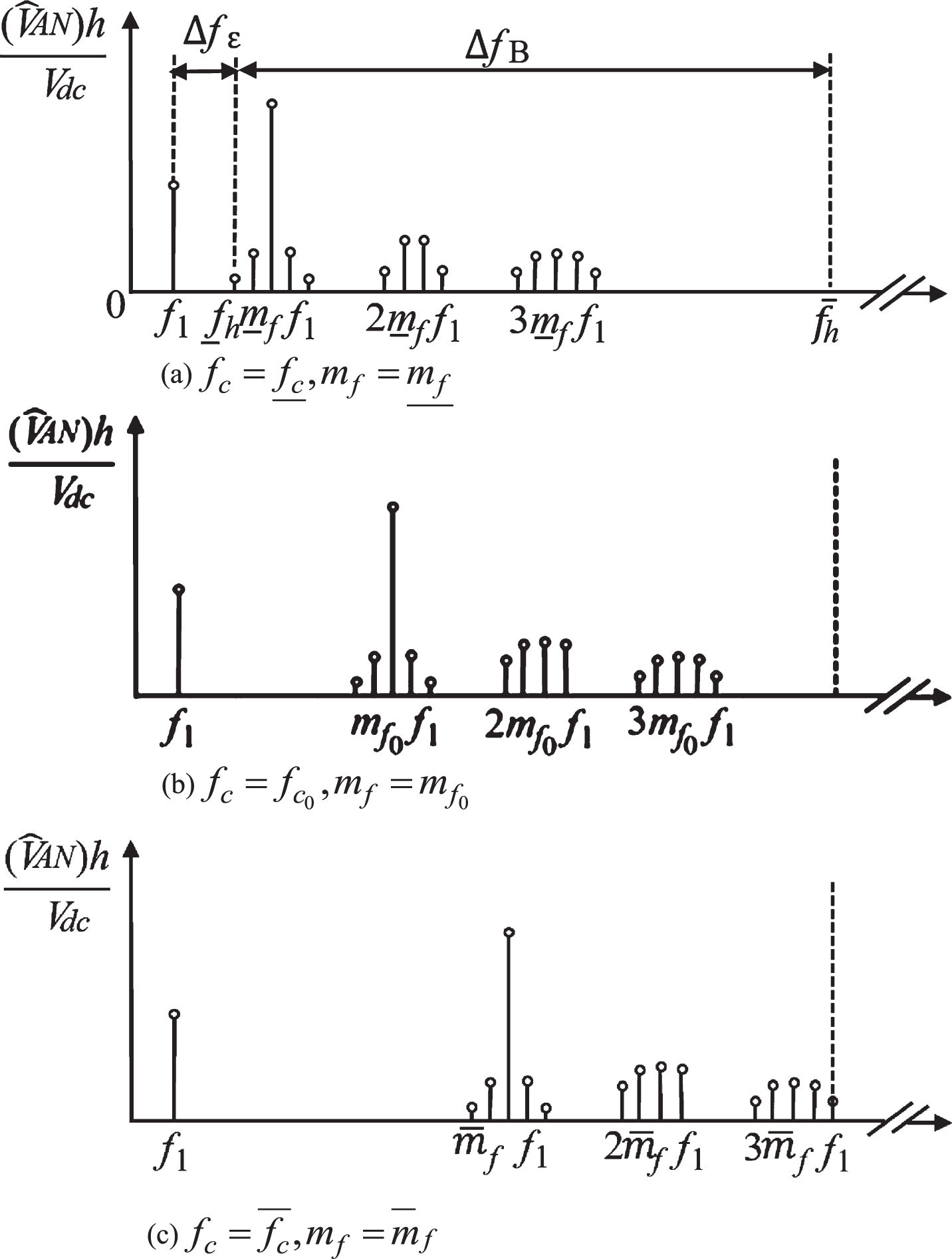
If the carrier ratio m f = f c /f1 was defined, where f c represented the carrier frequency and f1 represented the modulation wave frequency, the effect of RCFM control on power density spectrum of the inverter output phase voltage was shown in Fig. 4. As can be seen from Fig. 4, if the frequency of the preset carrier wave was too low, the lower harmonic component would be increased, which would not only cause the distortion of the output waveform of the inverter, but also cause mechanical vibration of the motor. Meanwhile, if the frequency of the preset carrier was too high, higher switching loss would occur. Therefore, the preset carrier needed to be designed according to certain principles.
Influence of RCFM control on power density spectrum of inverter phase voltage.
When the triangular wave signal of the lowest frequency (
Where,
We could receive
In the formula, the selection of Δf
ɛ
needed to consider the response frequency characteristics of the mechanical system and the maximum fundamental frequency
When the triangular wave signal of the highest frequency (
To solve the Formula 6, we could get Formula 7.
According to the above analysis, if the highest fundamental frequency If the highest working frequency of selected switching device was fmax, then The high switching frequency meant producing a higher frequency conduction EMI. If the highest frequency of EMI allowed for was fEMI, then
Simulation results
In the following, PWM of the fixed frequency method and the switching frequency randomization method proposed in this paper were simulated and analyzed, and the simulation parameters were shown in Table 1. Among them, the switching frequency adopted by the fixed frequency PWM was 13 kHz, and the four on-off frequencies preset in the random PWM method were 10 kHz, 12 kHz, 14 kHz and 16 kHz. The carrier switching frequency was selected as 2 kHz according to Formula 2. Since the frequency of the carrier signal adopted by the conventional PWM method was fixed, the energy of the high-frequency signal was concentrated on the switching frequency and the doubling harmonic frequency of the frequency spectrum obtained by Fourier transform on the output signal of the inverter, as shown in Fig. 5, wherein the signal amplitudes of Vds and Vab close to the on-off frequency ratio were 125 V and 82 V.
Experimental parameters of two-level three-phase inverter
Experimental parameters of two-level three-phase inverter
Inverter spectrum by conventional PWM control.
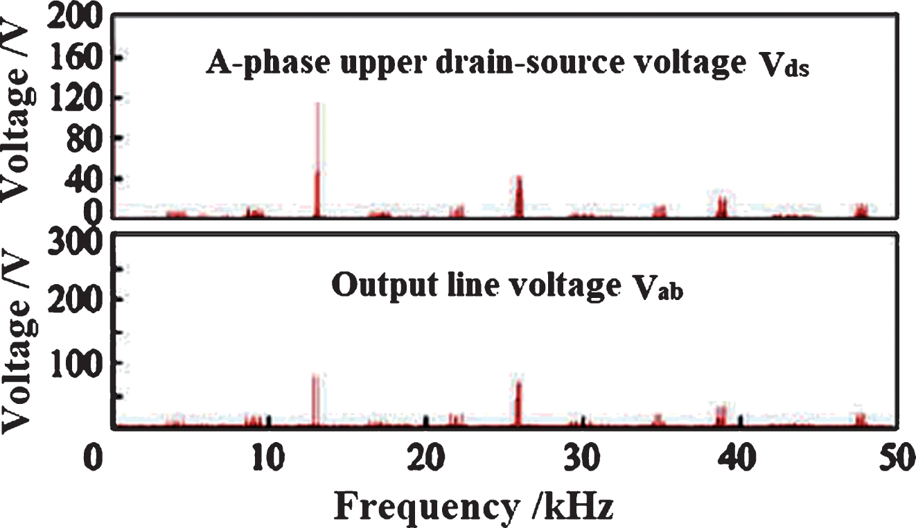
After using random PWM control, the energy near the original switching frequency was evenly distributed to the preset four switching frequencies, as shown in Fig. 6. The signal amplitudes of V ds and Vab near the switching frequency were reduced to 37 V and 24 V respectively, and it could be seen that random PWM effectively reduced the amplitude of higher harmonic.

Inverter spectrum by random PWM control.
In addition, in the random PWM method proposed in this paper, the influence of the clock signal frequency on the output phase voltage was simulated and analyzed in Fig. 7. From the figure, when the clock signal frequency was 1 kHz and 2 kHz, since both frequencies satisfied Equation 2, no obvious harmonic distortion was found from the simulation waveform of phase voltage. When the frequency increased to 3 kHz, although the randomization degree of the random signal increased, the modulation process produced a phase error and a visually discernible distortion of the phase voltage waveform due to not satisfying Equation 2.

Effect of different clock signal frequencies on the output phase voltage of inverter.
In order to verify the correctness of the simulation analysis, a two-level three-phase inverter prototype was built in the laboratory. The detailed parameters of the experimental system were shown in Table 1. The experiment mainly analyzed the harmonic spectrum of the leakage source voltage waveform of the switching tube with the help of the Fast Fourier analysis function provided by the oscilloscope itself.
The harmonic spectrum of the tube-drain source voltage on phase A of the inverter bridge under different PWM control were shown in Fig. 8. The harmonic spectrum of conventional PWM control was shown in Fig. 8a. It is obvious from the figure that the higher harmonic components in the waveform were distributed discretely, and the harmonic amplitudes at the switching frequency and frequency doubling frequency were higher.
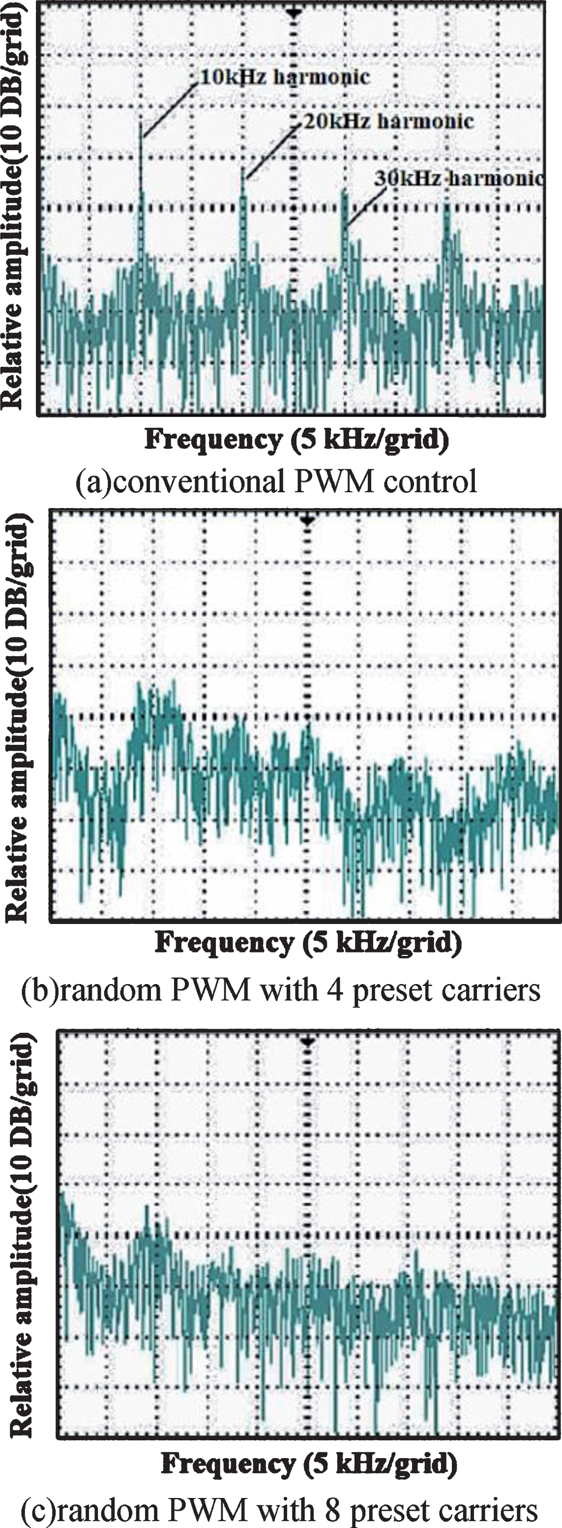
Leakage Source Voltage Spectrum of Switch Tube under Different PWM Control.
By using the random PWM control method proposed in this paper, four carrier waves were preset at first, and the frequencies were 9 kHz, 9.5 kHz, 10.5 kHz, 11 kHz. The clock signal frequency was set to 500 Hz, and the experimental results were shown in Fig. 8b. It could be seen from the graph that the dispersion of the frequency spectrum was basically eliminated, and the energy of the higher harmonic was evenly distributed over the entire frequency range, in which the harmonic amplitude around 10 kHz was reduced by 10 dB compared with the amplitude in Fig. 8a, and the harmonic amplitudes around 20 kHz and 30 kHz were weakened more significantly. The experimental results verified that the random PWM had a good ability of suppressing the higher harmonic.
Because there were only four preset carriers, the degree of randomization was not high enough, so that the harmonic amplitude near 10 kHz still had a small sharp front. Therefore, eight carrier waves were preset once more, and the frequencies were respectively 8 kHz, 8.5 kHz, 9 kHz, 9.5 kHz, 10.5 kHz, 11 kHz, 11.5 kHz, 12 kHz, and clock signal frequency was still 500 Hz. The experimental results were shown in Fig. 8c. As shown in Fig. 8c, obviously, the more the number of preset carriers were, and the higher the degree of randomization of the switching frequency was, the better the suppression effect of the higher harmonic was. It could be seen from the figure that the harmonic amplitude at the switching frequency was reduced by 5 dB compared with the case of using four carriers, and the harmonic spectrum became smoother.
The experimental waveforms of the inverter bridge input voltage V dc and three-phase voltage adopting the RCFM method proposed in this paper were shown in Fig. 9. As could be seen from the figure, the phase voltage waveform of the inverter under the random PWM control did not have obvious distortion, which proved the superiority of the RCFM method based on the preset carrier in improving the output waveform quality of the inverter.
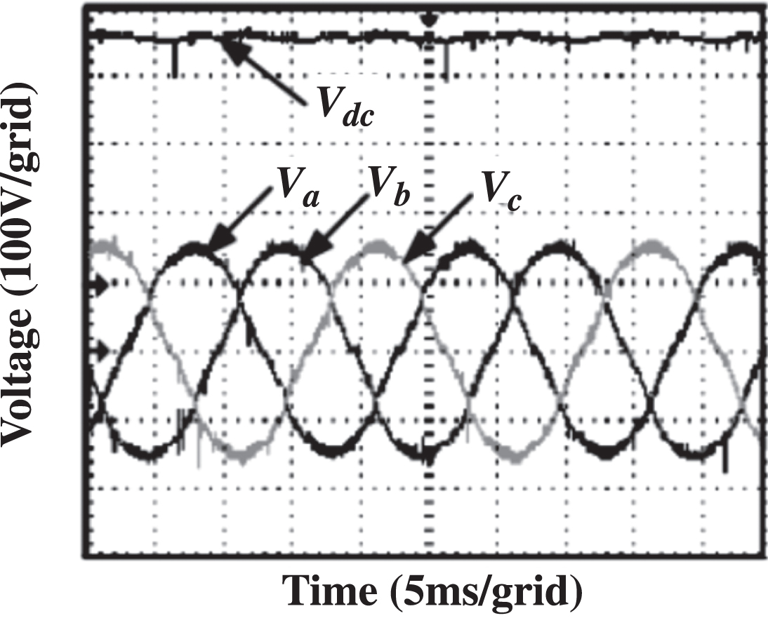
Experimental waveform of input and phase voltage of inverter bridge using random PWM method.
In this paper, the effect of clock signal frequency on carrier switching was analyzed. The results showed that when the carrier was switched randomly, the phase mismatch between the front carrier and the back carrier was the root cause of the inverter output voltage distortion. In order to solve this problem, the relationship between the clock signal frequency and all the preset carrier frequencies which must be satisfied was analyzed quantitatively, and the random switching of the preset carrier was proposed to realize the randomization of the switching frequency. In the proposed randomization scheme, the higher the number of preset carriers was, and the higher the degree of randomization of switching frequency was, the better the suppression effect of higher harmonic was. However, with the increase of the number of preset carriers, the hardware cost of the system would increase correspondingly, therefore, designers should make a compromise between the random modulation effect and the hardware cost.
Footnotes
Acknowledgments
The authors acknowledge the painstaking efforts of the research team members.