
Abstract
Traditional soybean seeders are driven by land wheels, which are easy to slip in complex operating conditions, resulting in the increased miss-seeding index and row-spacing coefficient of variation, etc. In order to solve these problems, a soybean electrical-control seeding system was designed in this paper. For improving the control accuracy of the electrical seeding system and achieving precise control of soybean seeding, the closed-loop control was adopted in the electric-driven Soybean Seeding system, the motor model of the electric-driven soybean seeding system was established and the transfer function of the motor was obtained. The PID control parameters were obtained by the Ziegler-Nichols PID tuning method, and the corresponding parameters were substituted into the control system simulation model established in MATLAB/SIMULINK. The conventional PID control system and the fuzzy PID control system were simulated respectively. Field trial results show that seeding with fuzzy PID control is better.
Introduction
With high speed development of the national economy in China, the farm mechanization level is getting higher and higher, and smart agricultural devices are the main features of farm mechanization in the country. Seeders are a major part of the agricultural equipment. Smart seeders do not save a lot of labors but show advantages of high seeding quality, high seeding efficiency, even row spacing, and seeds saving. Now mechanical seeders are always used in precision seeding, but they are driven by land wheels, which are easy to slip in field operating conditions, resulting in the increased miss-seeding index and row-spacing coefficient of variation [1–3]. Most of the domestic and foreign studies for soybean seeders are performed on structural design and performance parameter optimization of seeders [4–6]; pneumatic seeders feature complex structure, large product size, high power consumption, and high operating costs. In recent years, in agricultural mechanical seeding systems, Programmable Logic Controllers (PLCs) have been used as core controlling devices and fuzzy control algorithm (PID) used as control strategies. However, most of the studies are performed on row crop controllers and precision fertilization controllers, and the ones on precision control of soybean seeders are few [7–12].
In this paper, the fuzzy PID control method is used to optimize the control of the metering motor, and the comparison experiment between fuzzy PID control and conventional PID control is carried out. Fuzzy control is an intelligent control method based on fuzzy set theory, fuzzy linguistic variables and fuzzy logic reasoning. The purpose of fuzzy control is to make the three parameters KP, KI, KD in the PID controller self-adjustable with the variation of the deviation e and the deviation change rate ec.
In this paper, Section 2 research the principle of the seeding control system including some vital equations and parameters, Section 3 introduce the mechanism of motor fuzzy PID control, Section 4 present the design and simulation of the fuzzy PID controller through Matlab, Section 5 tell the experiments and results analysis including tests design, comparison, analysis.etc. Finally, it is concluded the full paper in Section 6.
Related work
S. Kamgar et al. designed a wheat planter with a seed control device. The encoder wheel mounted on the ground wheel and the seed shaft is used to detect the ground wheel speed and the seed shaft speed. A closed-loop controlled data processing system is used to control the operation of the motor to control the seed volume. The designed wheat planter equipped with the seed control device can effectively improve the uniformity of seeding and achieve precise seeding at high speed [14]. Hadi Karimi et al. used a signal detection technique to design a wheat planter for performance evaluation. The detection technique determines the amount of seed discharged by the seed meter based on the relationship between the strength of the falling seed impinging on the sensor and the change in the generated voltage value. An online determination procedure for seeding uniformity was prepared to evaluate the seeding performance of the wheat planter [15]. The electric drive type seeding system developed by Precision Planting in the United States replaces the traditional chain drive drive metering device. The speed measuring radar is used to obtain the working speed of the seeding machine, and the seed meter and the v Drive clutch form an electric drive type seed metering device. The seeding system does not require maintenance of the chain drive system, which simplifies the structure of the planter. During the operation, the user can independently control each row of seeding conditions to achieve precise seeding [16]. Gong Linong and others developed a community seeding electrical control system. The electronic control system is mainly designed for the cone tray type seeding mechanism.
The stepper motor and the DC motor are used to control the grid seed meter and the centrifugal distributor respectively. The system can adjust the rotation speed of the dispenser according to different kinds of seeds, can meet the requirements of different seeds for the rotation speed, and improve the accuracy and working efficiency of the plant sowing breeding test [17–19]. Shi Linyi and others designed an electric drive type corn film on the cornice. The motor-driven differential drives the whole machine to travel and provides power to the forward speed compensation mechanism. The optimized design of the forward speed compensation mechanism causes the displacement duckbill to move in a vertical direction relative to the ground. The linear electric push rod is used to adjust the rear wheel height to ensure that the front wheel and the rear wheel of the hole-drilling machine are at the same level, and the depth-limiting mechanism is used to adjust the depth of the hole. Experiments were carried out under different design sowing conditions. The results show that the electric drive type seeding machine can meet the basic requirements of seeding corn sowing and improve the mechanization degree of the seed corn [20–22]. The above scholars have carried out related seed control research, but did not carry out the research on the effect of fuzzy PID control applied to soybean grain control.
Operating principle of electrical-control seeding systems
When the electrical-control seeding system operates, a Hall-type speed sensor collects real-time operating speed of the system, and then the theoretic seeder speed is calculated out by PLC with row-spacing calculation formula; with fuzzy control strategies, the real-time seeder speed collected by a coder is used for PID parameter optimization based on genetic algorithm, in order to yield the best seeder speed. Then the motor driver is adjusted to output a corresponding PWM duty cycle in order to regulate motor speed for increased seeding precision.
Relationship between seeding speed based on row spacing and seeder speed
In order for precision seeding and even row spacing, seeders need to be controlled in a precision manner, i.e. when the seeder traveling speed is high, the speed of stepping motor driving the seeders shall increase accordingly; when the seeder traveling speed is low, the speed of stepping motor shall decrease accordingly. This requires a function to represent the relationship. In the test in this paper, an indented seeder was used for precision seeding of each seed in each hole, so:
Where l: row spacing; S: seeding distance; M: number of seeds
V1: traveling speed; T1: travelling period
N: seeding number in unit time; T2:seeder revolution time;
The seeder speed V2 is dependent on the pulse X received by the stepping motor to control its speed. By substituting the steps setting of stepping motor, seeding number, etc. as a constant A, it yields:
The main purpose of the electric driven soybean seeding system is to control motor speed. Assuming that the motor operates in ideal conditions, its differential equation based on motor theories is [13]
Td ——Electromagnetic time constant, s
Tm ——Mechanical time constant, s
n _ 1——Motor speed, r/min
K e ——Motor back-EMF constant, V⋯/rad
U0——Armature voltage, V
After Laplace transform, it yields the transfer function of the stepping motor:
Electromagnetic time constant refers to the time that the armature current reaches 63.2% steady current with applying voltage at the armature input, equal to the ratio of armature inductance to the total resistance of the armature circuit.
L a ——Armature inductance, H;
R m ——total resistance of the armature circuit, Ω;
Mechanical time constant refers to the time that the motor speed reaches 63.2% of the stable speed from 0 r/min when the motor is rated excitation and the step voltage is applied to the armature input.
n:number of seeder revolutions; K:number of indents in the seeder;
At a given row spacing, the seeder traveling speed, seeder speed, and pulse equivalent of stepping motor have the following relationship:
J a ——Rotational inertia of motor, kg·m2
K t ——Torque constant, N·m/A
The back-emf constant is the back-EMF value per unit speed. The ratio of the open circuit voltage to the speed of the generator is the back EMF constant when the motor operates in the generator situation. Back-EMF constant and torque constant are both functions of the air gap flux and armature conductor numbers, so they can be converted to each other, K t = K e .
This test was performed with brushless DC motors, with its main parameters of inductance L
a
= 0.0218H, R
m
= 2.384Ω, J
a
= 0.002 kg m2, K
e
= 0.085 V⋯/rad, so
Fuzzy control is an intelligent control method based on fuzzy set theory, fuzzy linguistic variables and fuzzy logic reasoning. The purpose of fuzzy control is to make parameters KP, KI, KD self-adjust with the deviation value e and deviation rate ec. The fuzzy controller includes the fuzzification interface module, the knowledge base composed of database and rule base, the fuzzy reasoning module and the deblurring interface module. In nature, the fuzzy PID control combines the fuzzy controller and the PID controller to control the controlled object together. Fuzzy PID control system as shown in Fig. 1.
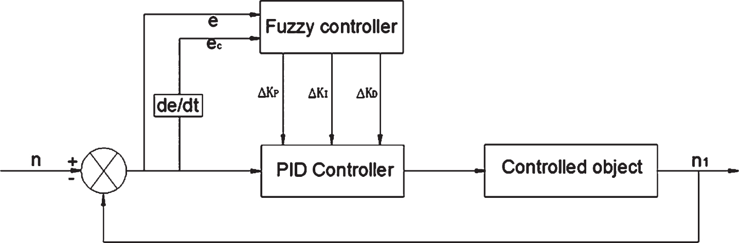
Fuzzy PID control system.
PID closed-loop control, the regulator control algorithm, is the most widely used in engineering practice. In order to achieve the purpose of regulating control, it corrects the response of the system by liner combination computation of proportion, integral and differential from the deviation between the expected input value and the actual output value of the controlled objects. A complete closed-loop control system consists of three elements: measurement, comparison and execution. Its basic principle is to compare the expected value with the actual output value so as to calculate the system response deviation.
e(t) ——Deviation of system response
r(t) ——Expected value
y(t) ——Actual output value
According to the setting of each parameter in the PID regulator, the deviation value e(t) is processed, and the output signal is adjusted to realize the control of the controlled object. The control principle diagram as shown in Fig. 2.
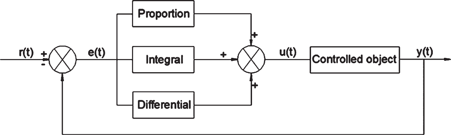
PID control system principle.
The relationship of each parameter in the PID regulator as shown.
u(t) ——Output signal of regulator;
e(t) ——Deviation signal of regulator;
KP ——Proportionality coefficient
TI ——Integral time constant
TD ——Differential time constant
Control law of PID regulator as follows
KP ——Proportionality coefficient
TI ——Integral coefficient
TD ——Differential coefficient
e(t) ——Speed deviation
ec(t) ——Speed deviation rate
According to the function and formula (14) of each control parameter, It is essential to select appropriate PID parameters to control motor accurately. The tuning of PID parameters is one of the most important parts in the design of the PID regulator. For the purpose of realizing better control effects, It is necessary to improve the dynamic and static indexes of the system by changing the parameters of the regulator. However, PID turning is widely achieved by Ziegler-Nichols at present. This method is based on the system transfer function to adjust the proportionate, integral and differential parameters. Its advantage involves that it does not need to establish any object model, simple and easy to operate, and can quickly and accurately calculate the value of each control parameter. The radical locus of DC brushless motor transfer function can be obtained by the Ziegler-Nichols programme of Matlab. Its radical locus graph as shown in Fig. 3.
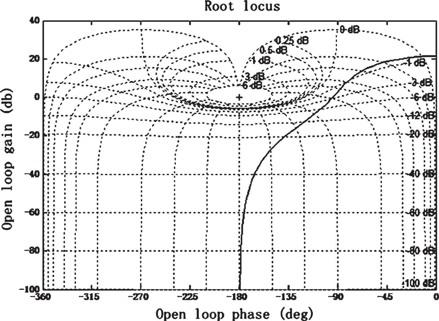
Radical locus of the motor transfer function.
According to the radical locus of the motor transfer function and the point crossing the j
ω
axis, open-loop gain Zm = 17.8 dB and crossover frequency Wm=85.6 Hz of the transfer function can be obtained. Considering the turning formula of PID.
In order to research whether parameters obtained from the PID turning formula can be applied to the electric drive seeding system, it is essential to make simulation analysis. Throw KP, KI, KD into the PID control model established by Matlab/Simulink. The model structure as shown in Fig. 4.
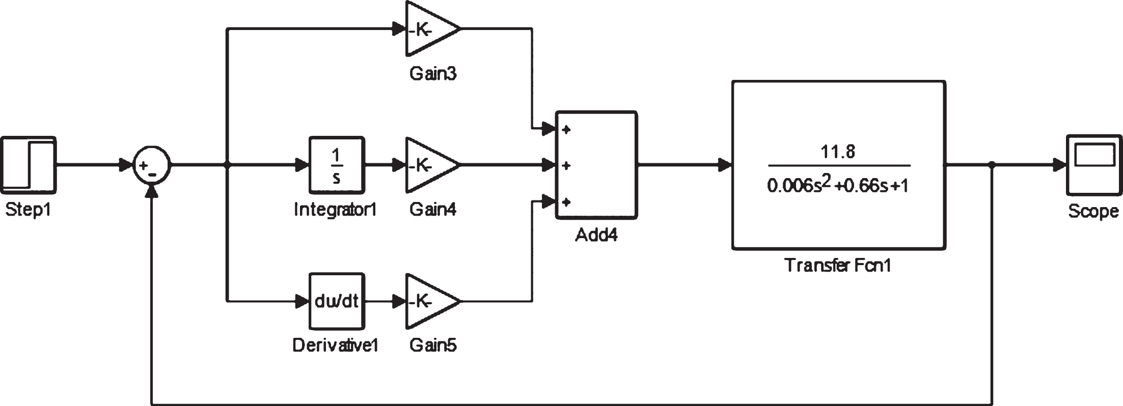
PID control model.
In the Step modular of the model, step time is set to 0.5 s, the initial value is set to 0. Based on the speed requirement of the seeding device, the final value is set to 50, the sampling time is set to 0, simulation time is set to 4 s. A variable step-size ode45 function solver is adapted. The results of simulation as shown in Fig. 5.
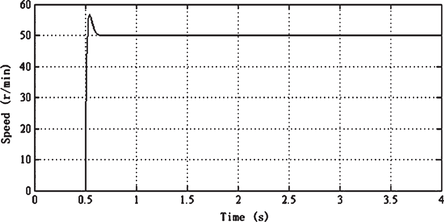
Results of PID control simulation.
After analyzing Fig. 5, There is a larger overshoot although using Ziegler-Nichols frequency response method which has a better response speed and lower steady-state error. So it is necessary to design the fuzzy PID regulator to search a better control effect to reduce the overshoot value and improve the steady-state speed.
Fuzzy control is an intelligent control method based on fuzzy set theory, fuzzy linguistic variables and fuzzy logic reasoning. The purpose of fuzzy control is to make parameters KP, KI, KD self-adjust with the deviation value e and deviation rate ec. The fuzzy controller includes the fuzzification interface module, the knowledge base composed of database and rule base, the fuzzy reasoning module and the deblurring interface module. In nature, the fuzzy PID control combines the fuzzy controller and the PID controller to control the controlled object together. Fuzzy PID control system as shown in Fig. 1.
In this paper, considering the electric driven soybean seeding system, the fuzzy controller input signal is the deviation e and deviation rate ec formed by the motor speed feedback value detected by the driver and the motor speed theoretical value detected by the Hall sensor. During the process of motor operation, the sensor detects e and ec continuously. After reasoning, deciding by the fuzzy regulation rules, ΔKP, ΔKI, ΔKD were obtained by deblurring. The real-time corrected values are are combined with the initial PID parameters KP, KI and KD of the system respectively.
Some new parameters KP,KI,KD are obtained by superimposing the initial value and the revised value so as to adjust proportionate, integral and differential parameters of PID controller. In order to control the electric driven seeding system accurately, PID control parameters were adjusted continuously to meet requirements of deviation e and deviation rate ec.
In this paper, the fuzzy controller was designed by two-dimensional control structure. The input of the fuzzy controller could be used to calculate the control output after defuzzification. The input interface of the fuzzy controller is speed deviation e and deviation rate ec. The FIS inference controller of mamdani type was selected to achieve defuzzification and output PID revised values through gravity method.
According to the actual operating situation of the electric driven soybean seeding system, the discourse universe of e and ec were [–5, 5]. Tuning parameter results were obtained by Ziegler-Nichols frequency response method. The discourse universe of ΔKP was [–2, 2]. the discourse universe ΔKI of was [–10, 10]. The discourse universe of ΔKD was [–0.1, 0.1].
Considering the features of fuzzy control and affection of motor control performance, some control parameters were adjusted, and the control rules base was built by combining expertise knowledge and working experience of operators. According to the membership degree distribution of the established fuzzy variables, the corresponding fuzzy rules are obtained. After editing the fuzzy control rules, the output surface of the PID parameters could be observed through the viewing window of the surface. The output surface of ΔKP, ΔKI, ΔKD as shown in Figs. 6–8 respectively.
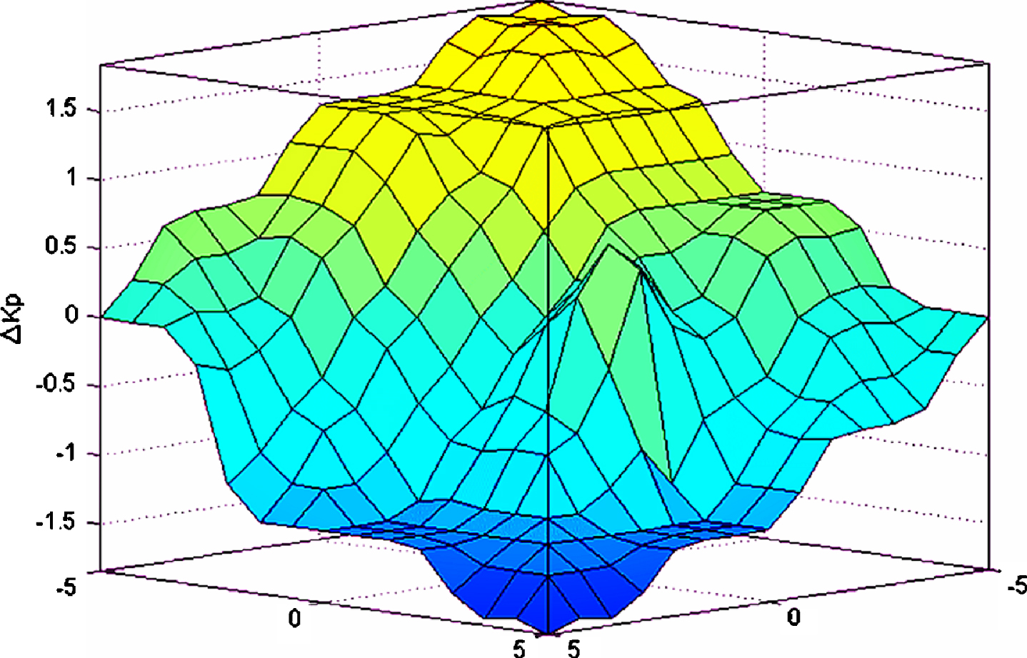
Output surface of ΔKP in the discourse universe.
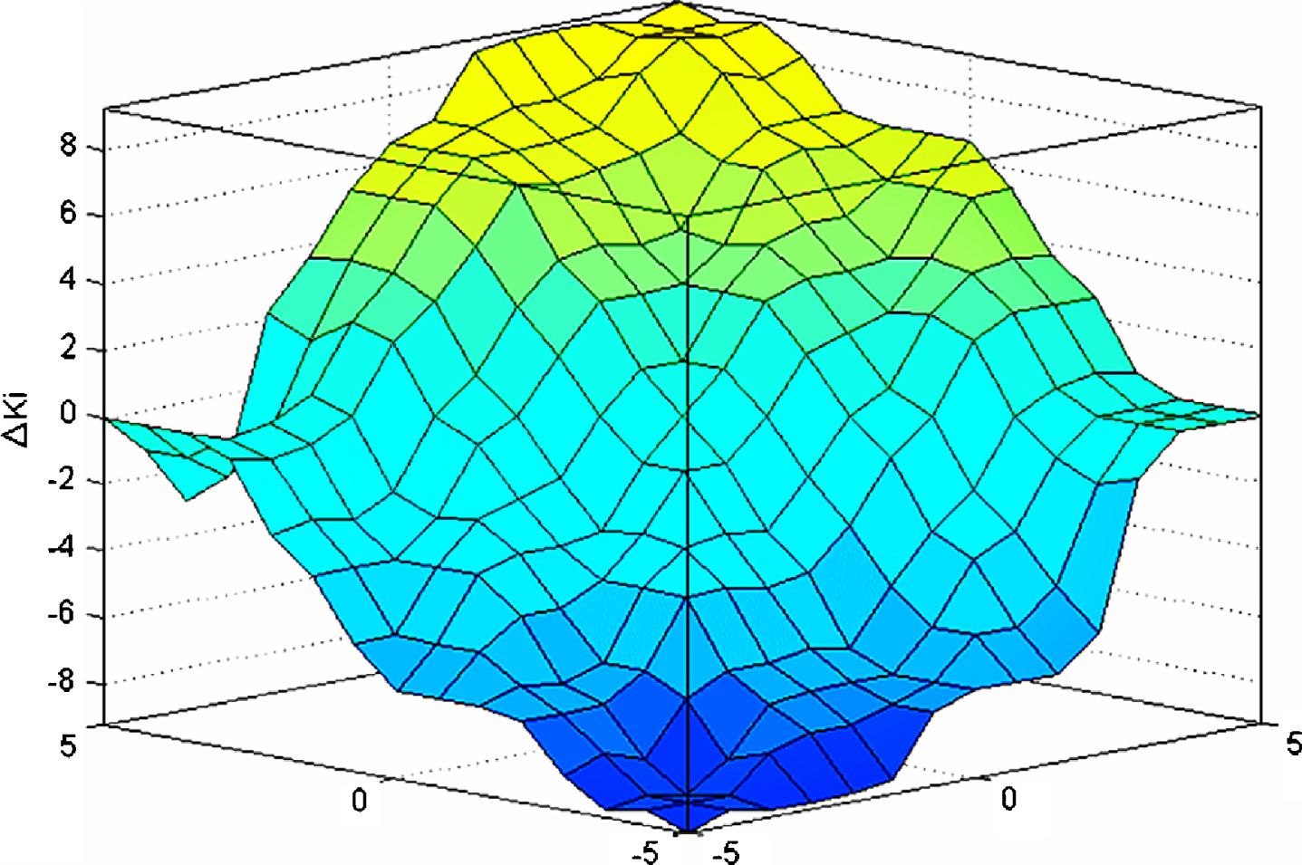
Output surface of ΔKI in the discourse universe.
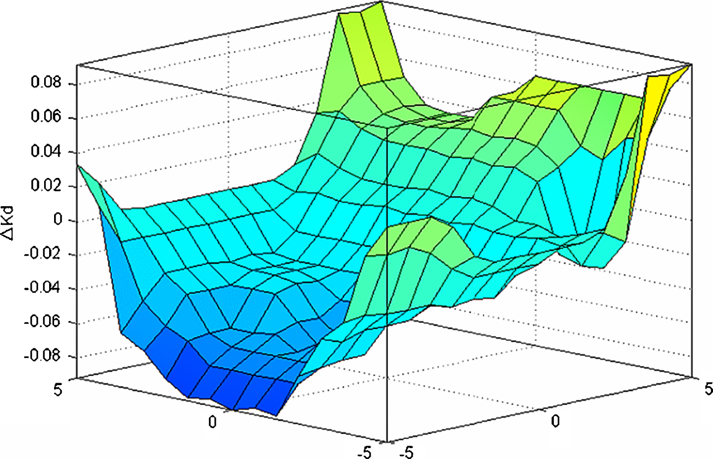
Output surface of ΔKD in the discourse universe.
The parameters obtained by the fuzzy control reasoning in the fuzzy controller were all fuzzy variables, which could not be directly used as the control variables of the electric drive seeding control system. Therefore, it was necessary to convert the fuzzy variables into clear control outputs so as to obtain the corrections of the PID parameters. When tuning the parameters of PID, the exact values of ΔKP, ΔKI, ΔKD in the discourse universe were obtained according to the query results of the fuzzy decision table, and then multiplied by the corresponding scaling factors, finally the corrections of PID parameters could be obtained.
Based on the designed fuzzy controller, the fuzzy simulation control model of the electric driven seeding system was established. The parameters of PID were embedded into regular PID controller by using fuzzy control programme so as to constitute the fuzzy PID control model of the electric driven seeding system. The simulation model as shown in Fig. 9.
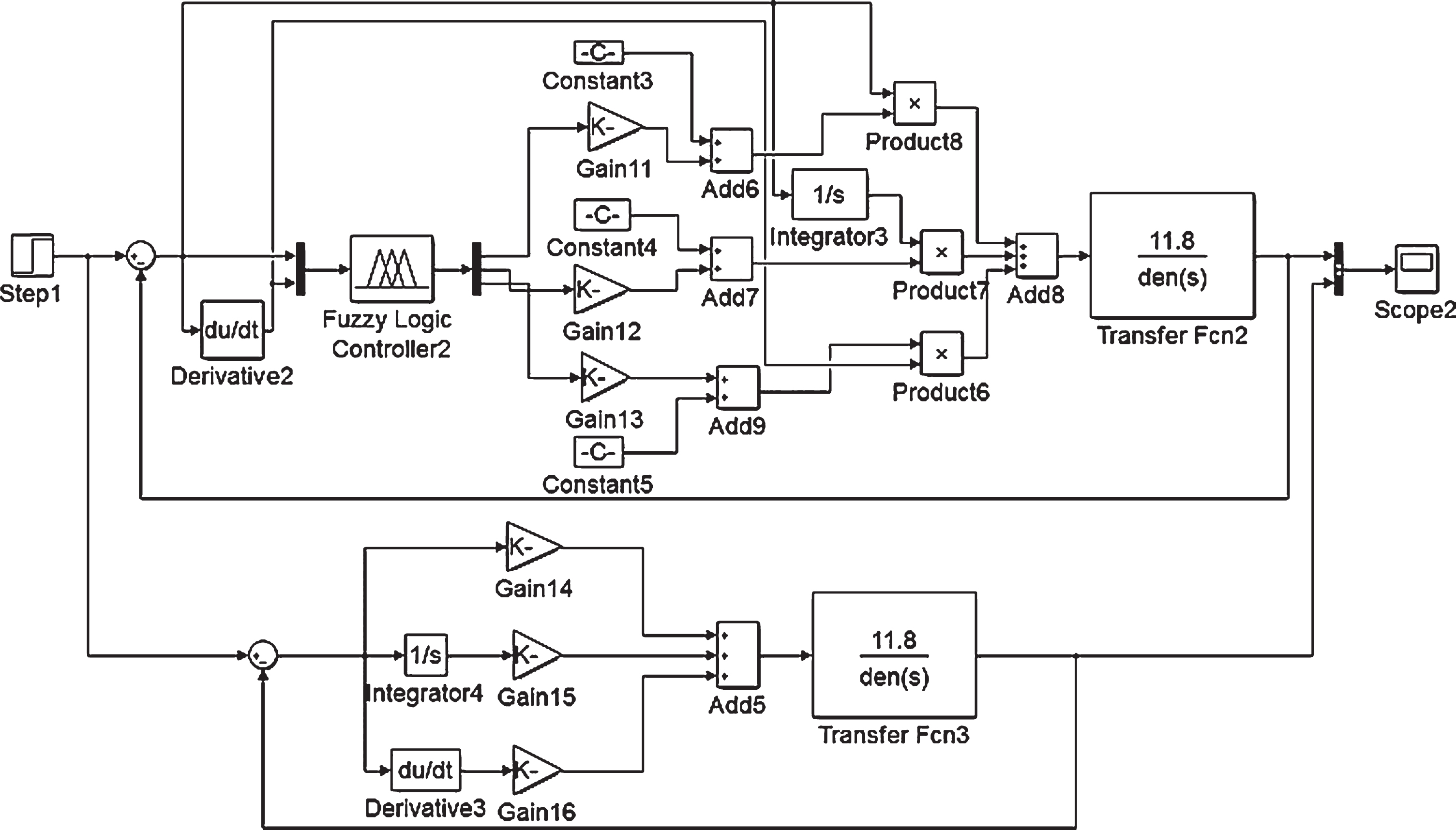
Fuzzy control simulation model.
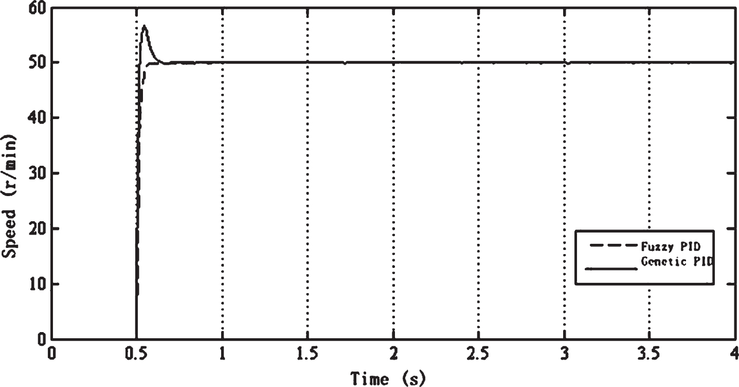
The simulation results of systematic step response comparison between conventional PID control and fuzzy PID control in Fig. 10.
Figure 10 shows that conventional PID control systematic step response curve in the solid line and fuzzy PID control systematic step response curve in the dotted line. The simulation results of the electric-driven soybean seeding system under the two control models were compared.
The results comparison of system simulation.
When the system was simulated with the fuzzy-PID control, the system did not overshoot and the time of reaching the steady-state was shorter than the conventional PID control, and the dynamic response was faster.
Precision test for the control system
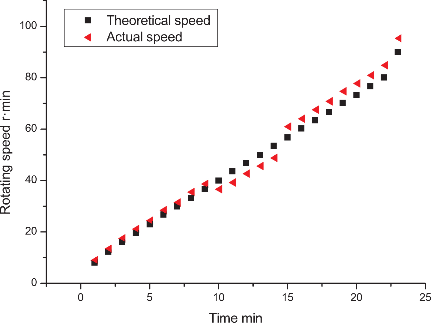
With ZH-39 soybean as test material, the test was performed in a test field of Zhengzhou Rongda Technical Co., Ltd. in Wuzhi County. The test field is 300 m long and 150 m wide. In each test, 100 pieces of data after stable seeding were collected and such collections were repeated three times, averaging test results. By targeting theoretic seeder speed and real-time seeder speed at three seeding speed ranges of 0–3 km/h, 3–6 km/h and 6–9 km/h, their difference was used to represent control precision. The result and relative error of conventional PID control tests were shown in Figs. 11 and 12, while the results and relative errors of fuzzy PID control tests were shown in Figs. 13 and 14.
Speed curve in conventional PID control.
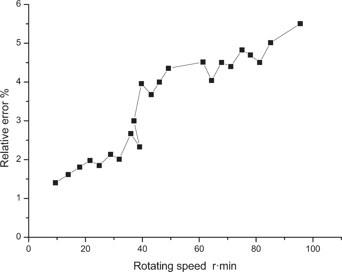
Relative error curve in conventional PID control.
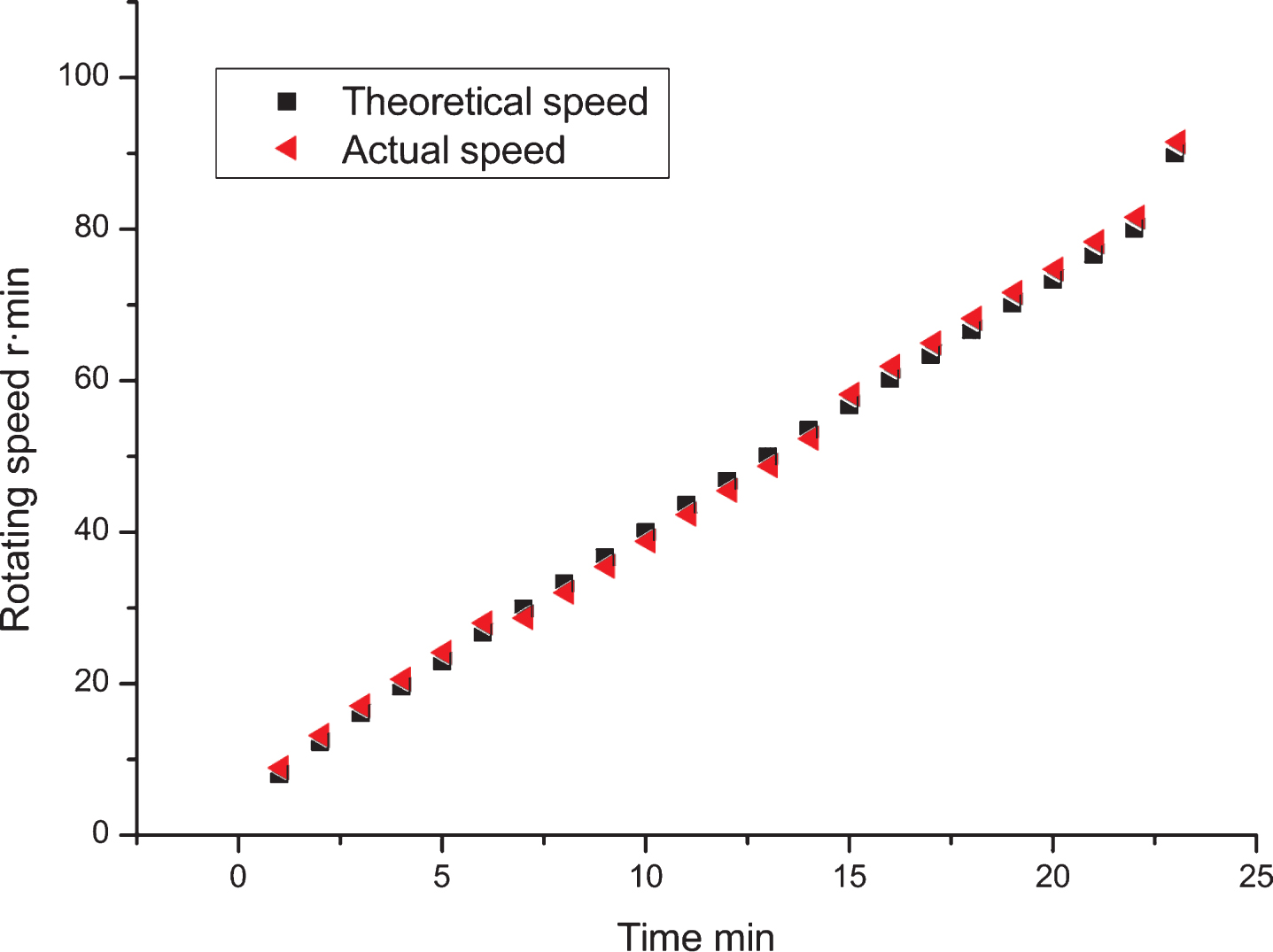
Speed curve in fuzzy PID control.
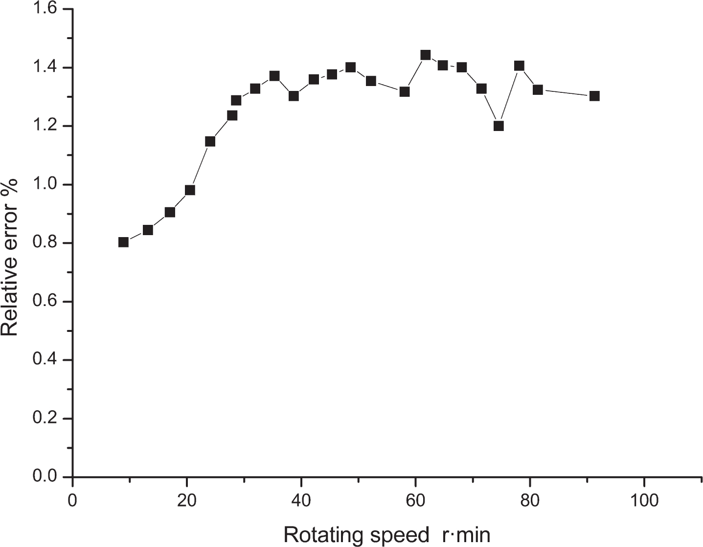
Relative error curve in fuzzy PID control.
In Figs. 11–14, when using conventional PID control, the seeder traveling speed was 0–3 km/h and the corresponding speed of seeder shaft was 0–40 r/min, and the difference between theoretic shaft speed and actual shaft speed was small, with relative error equal to 1.46–2.67%; as the seeder traveling speed became high, the corresponding speed of seeder shaft increased and the difference between theoretic shaft speed and actual shaft speed also increased progressively (the higher the shaft speed, the greater the difference), with relative error equal to 2.33–5.58%.
When using the fuzzy PID control, the seeder traveling speed is 0–9 km/h, and the corresponding speed of the seeder shaft is stable, showing a smaller global error. Especially in the speed range of 0–6 km/h, the difference between theoretic shaft speed and actual shaft speed is very small, with relative error equal to 0.81–1.44%. Compared to conventional PID control, the fuzzy PID control showed a larger stable-control range and better control effect.
According to GB/T 6793-2005 Testing methods of single seed drills (precision drills), parameters of acceptability index, repeated-seeding index, miss-seeding index, and row-spacing variation coefficient were chosen as seeding performance indicators in the test. Test results were summarized in Tables 1 and 2.
Performance indicators of traditional seeding systems at different operating speeds
Performance indicators of traditional seeding systems at different operating speeds
Performance indicators of electrical-control seeding systems at different operating speeds
When a traditional seeding system was used for field operations, the maximum value of repeated-seeding index is 3.36% in high-speed operations, and its minimum value is 2.02% in low-speed operations; the maximum value of miss-seeding index is 4.25% in high-speed operations, and its minimum value is 2.06% in low-speed operations; and the maximum value of row-spacing variation coefficient is 6.48% in high-speed operations, and its minimum value is 3.62% in low-speed operations. When an electrical-control seeding system was used for field operations, the maximum value of repeated-seeding index is 1.35 % in high-speed operations, and its minimum value is 0.92 % in low-speed operations; the maximum value of miss-seeding index is 1.22% in high-speed operations, and its minimum value is 0.98 % in low-speed operations; and the maximum value of row-spacing variation coefficient is 3.69 % in high-speed operations, and its minimum value is 2.15 % in low-speed operations. The electrical control seeding system shows good performance indicators in medium-speed and low-speed operations.
Considering precision farming requirements, an electrical-control seeder system driven by a stepping motor was designed to solve the problem of lower seeding precision of current seeding control systems. Then a corresponding transfer function and Simulink model were created and PID parameters were optimized with a genetic algorithm, in order to improve the control precision. The motor model is established, the motor transfer function is obtained, the fuzzy controller is designed, and the electric drive seeding simulation model is established. The simulation results show that the fuzzy PID controller is designed, the system has no overshoot, and the steady state time is short. Fast response. Field tests showed that, when seeding the soybean with the electrical-control seeding system, the repeated-seeding index averaged 1.17%, less than 1.55 percentage points compared to that of traditional seeding; the miss-seeding index averaged 1.19%, less than 2.12 percentage points compared to that of traditional seeding; and the row-spacing coefficient of variation averaged 2.68%, less than 2.27 percentage points compared to that of traditional seeding. So when seeding with the electrical-control seeding system, all of its indicators met precision seeding requirements, showing good seeding effect.
Footnotes
Acknowledgments
This research was supported by the “thirteenth five-year” positions scientists specific of China Agriculture Research System (Grant No. CARS-04-PS-25).