
Abstract
In order to solve the problem of poor simulation accuracy of the traditional method for the coupled vibration of high-speed railway track, a discrete element simulation method for the coupled vibration of high-speed railway track under load is proposed. Based on the coupled vibration equation of high-speed railway track, the coupled vibration equation of high-speed railway track is built on the basis of determining the vector and parameters. The discrete element model is used to analyze the coupled vibration of high-speed railway track under the action of load, and the results of the discrete element simulation experiment of the coupled vibration of high-speed railway track are obtained. In order to verify the simulation accuracy of the proposed discrete element method, a comparative experiment is designed. According to the experimental results, the proposed discrete element simulation method for coupled vibration of high-speed railway track under load greatly improves the simulation accuracy. In the 100th experiment, the simulation accuracy of this method is as high as 93%. The coupling vibration discrete element simulation method has better simulation effect.
Introduction
The railway transportation mode has the characteristics of large capacity, low operation cost and low energy consumption, which effectively links the whole country and the national economy. No matter in the aspect of medium and long distance passenger and freight transportation with large flow, or in the aspect of medium and short distance passenger transportation with large flow and high density, the railway transportation mode has great advantages and strong competitiveness, which is the most suitable transportation mode for China’s economic form, geographical conditions and people’s income level. China has always attached great importance to the development of railway transportation industry, especially the development of high-speed railway. With the opening and operation of Beijing-Tianjin intercity railway, the first high-speed railway in China, the high-speed railway has developed into a relatively complete technical system and built a number of high-speed railways with the world’s advanced level [11].
There are two types of railway track structure: ballasted track and ballast less track. Ballasted track is the traditional track structure of railway. It has the advantages of good elasticity, low price, convenient maintenance and good noise absorption. However, with the rapid development of high-speed railway, the operation speed of the train is increasing, and the disadvantages of ballasted track are gradually exposed, such as the shorter maintenance period of ballasted track, the increase of maintenance cost, the poor stability of the ballast bed on the bridge and tunnel, and the ballast splash caused by high-speed train. These disadvantages limit the application of ballasted track in high-speed railway. However, in the new high-speed railway, for sections with unfavorable geology and long-span bridges, it is still necessary to lay ballasted track. Compared with ballasted track, ballast less track avoids the splashing of ballast. It has the advantages of good smoothness, good stability, long service life, good durability and less maintenance work. It is an advanced track technology widely used in the world. However, China’s high-speed railway is still dominated by ballasted track. Under the action of load, high-speed railway ballasted track has the advantages of large capacity, high efficiency and low transportation cost. It has gradually become an important way of coal, ore energy and bulk cargo transportation in the world. Increasing the axle load of the train is an effective way to improve the transportation capacity of the heavy haul railway, but at the same time, it will obviously increase the dynamic effect of the train on the track, accelerate the damage of the track structure and the deterioration of the track bed, and finally have a negative impact on the traffic safety. In order to ensure the safety of high-speed railway transportation, the coupling vibration of high-speed railway track under load is studied [16, 17].
The high-speed railway track coupled vibration dynamics simulation method can effectively simulate the force of the coupled vibration process and can accurately simulate the vibration deformation. However, it requires higher experimental conditions and is greatly affected by external influences. The high-speed railway track-coupled vibration mechanics simulation method can classify the force of the vibration process into various directions, but the experimental process is not complicated and the feasibility is poor. The finite element simulation method of high-speed railway track coupled vibration is relatively simple, but the simulation accuracy is poor. These methods are based on the theoretical model of the continuum mechanics method, which cannot reflect the meso-mechanical characteristics of orbit coupling vibration, and the simulation results are quite different from the actual ones. In order to solve the above problems, the discrete element method is introduced into the research of railway track coupling vibration, trying to reveal the track coupling vibration behavior more comprehensively from the macro and micro level by combining the discrete element numerical simulation with the experimental research. The discrete element method was proposed by Cundall in 1971. It is a numerical method to show the solution. This method is similar to other display calculation in time domain, such as the display difference scheme for solving parabolic partial differential equation. The discrete element method, like the finite element method, divides the region into elements. However, due to the control of discontinuities such as joints, the element nodes can be separated in the later movement process, that is, one element can contact or be separated from its adjacent elements. The force of interaction between elements can be calculated according to the relationship between force and displacement, while the motion of individual elements can be determined according to Newton’s law of motion completely according to the magnitude of unbalanced force and unbalanced moment. After the finite element method and computational fluid dynamics, this method is another powerful numerical method used to analyze the dynamics of material system. Discrete element method provides a platform for solving many comprehensive problems involving particles, structure, fluid, electromagnetism and their coupling by establishing a parameterized model of solid particle system to simulate and analyze particle behavior. It has become a powerful tool for process analysis, design optimization and product research and development. Through the application of the discrete element method, the simulation accuracy of the coupled vibration of high-speed railway track under the action of load can be greatly improved, and the performance of the proposed method can be verified by the design of simulation contrast experiment [4].
Basic definitions
Construction of coupled vibration equation for high speed railway track
The coupled vibration of high-speed railway track is mainly caused by the interaction of train, ballast track and bridge. Therefore, based on the principle of the total potential energy of the elastic system dynamics, the coupled vibration equation of high-speed railway track is established [23].
According to the principle of constant value of total potential energy of elastic system dynamics proposed by academician Zeng Qingyuan, the idea of constructing coupled vibration equation of train, track and bridge is as follows: first, consider train, track and bridge as an integral system, and the wheel rail force as the internal force of the system; second, calculate the total potential energy of the system, including the gravitational potential energy, elastic strain energy, damping potential energy and inertial force potential of the system Energy; third, the variation of the total potential energy of the system; fourth, the matrix equation of the coupled vibration of the system can be easily obtained by using the “seat to seat” principle of forming the matrix proposed by academician Zeng Qingyuan [8]. The specific construction process of coupled vibration equation of high-speed railway track is as follows.
Determination of displacement vector
Set 13 independent degrees of freedom for each train of high-speed railway, and the expression is:
Among them, Y c means the vehicle body sway; Z c means the vehicle body sink and float; θ c means the vehicle body roll; ψ c means the vehicle body shake its head; β c means the vehicle body nod; Yt1 means the bogie sway; Zt1 means the bogie sink and float; θt1 means the bogie roll; ψt1 means the bogie shake its head; Yt2 means the wheelset sway; Zt2 means the wheelset sink and float; θt2 means the wheelset rolls; ψt2 means the wheelset shakes its head.
The rail displacement matrix X r of Order (6 × n r + 6) × 1 can be expressed as:
Where n r represents the total number of rail elements.
The displacement matrix X slab of track plate with order (6 × n slab + 6) × 1 is expressed as
Where n slab represents the total number of elements of track plate.
The bridge displacement array X b with order (6 × n b + 6) × 1 is:
Where n b represents the total number of units of the bridge.
The total kinetic energy of train vibration is expressed as:
Among them, M c represents the mass of the car body; J cθ represents the mass inertia around the x-axis of the car body; J cψ represents the mass inertia around the z-axis of the car body; J cβ represents the mass inertia around the Y-axis of the car body; M tj represents the mass of the j bogie; J tθj represents the mass inertia around the x-axis of the car body; J tψj represents the mass inertia around the z-axis of the car body.
The first-order variations of the above formula is carried out, and according to the rule of the general coordinates of the number of the train, the mass matrix, the total spring deformation potential energy, the stiffness matrix and the damping force work of the train are obtained.
Among them, [M] v represents the mass matrix of the train; V represents the potential energy of the total spring deformation; [K] v represents the stiffness matrix of the train; Q represents the work done by the damping force of the train; a2 represents the auxiliary parameter; χ represents the bogie position function.
The track parameters are mainly the mass matrix, stiffness matrix and damping matrix of ballasted track, expressed as:
Among them, M
slab
represents the mass matrix of ballasted track; K
slab
represents the stiffness matrix of ballasted track; C
slab
represents the damping matrix of ballasted track;
The bridge parameters are mainly the mass matrix, stiffness matrix and damping matrix of the bridge, which are expressed as:
Among them, M b represents the mass matrix of the bridge, K b represents the stiffness matrix of the bridge, C b represents the damping matrix of the bridge, N b represents the shape function matrix of the k bridge element, Kb1, Kb2 represent the stiffness matrix of the bridge itself and the stiffness matrix caused by the distribution spring under the track plate, Cb1, Cb2 represent the damping matrix of the bridge itself and the damping matrix caused by the discrete distributed damping on the bridge deck.
By integrating the above vector and parameters, the coupled vibration equation of high-speed railway track is obtained:
Through the above process, the high-speed railway track coupling vibration equation is built, which provides support for the following discrete element simulation of high-speed railway track coupling vibration [12].
Based on the above-mentioned coupled vibration equation of high-speed railway track, the discrete element method is used to build the discrete element model of track [19, 20]. The specific process is as follows.
High speed railway track is constructed by a typical coarse-grained material. In order to build the discrete element model of high-altitude railway track, it is necessary to build the discrete element model of single high-altitude railway track [18]. In consideration of the irregular geometry and sharp edges and corners of high-altitude railway track materials, the 3D laser scanning technology is used to obtain the real geometry of high-altitude railway track materials and build the discrete element model of high-altitude railway track based on it [22]. Figure 1 shows the three-dimensional scanning image and the discrete element model of partial height railway track material samples obtained by this method.
From Fig. 1, it can be seen that the discrete element model constructed can simulate the real irregular geometry of high-altitude railway track material samples more realistically. By using such a discrete element model, the over rotation of the track can be avoided in the simulation of the coupled vibration of the high-speed railway track, so that the coupled vibration of the high-speed railway track can be well simulated on the mesoscopic scale [3].
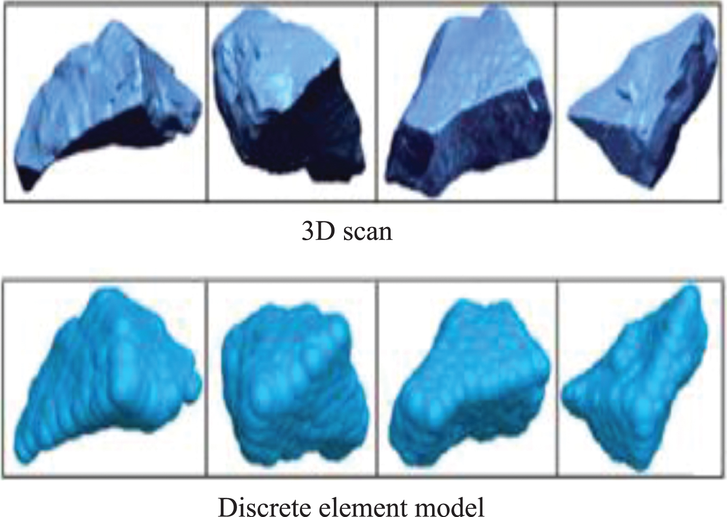
Schematic diagram of 3D scanning image and discrete element model of high rail material sample.
After the discrete element modeling of high-altitude railway track, the sample database of discrete element model of high-altitude railway track is constructed. According to the grading standard of the first level high railway track, the discrete element model of high railway track with different materials is selected randomly from the sample database [14]. These materials are stacked and compacted in the discrete element software to establish the discrete element model of high-speed railway track under the load as shown in Fig. 2.
In the discrete element model of high-speed railway track, the grading curve of ballast particle size is shown in Fig. 3.

Schematic diagram of discrete element model of high speed railway track under load.
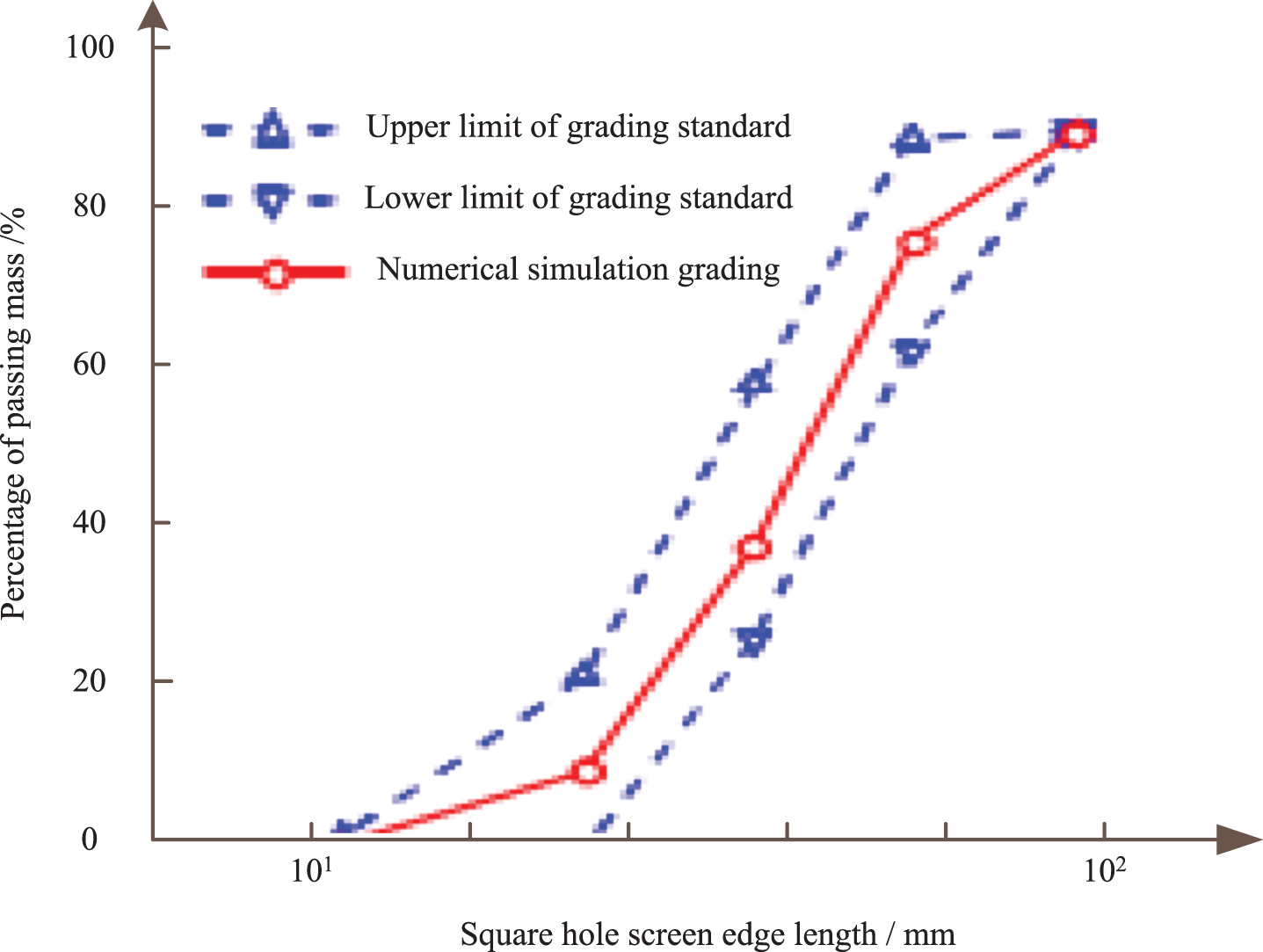
Schematic diagram of ballasted particle size grading curve.
The linear spring damping model is used to calculate the contact force between the track materials. The tangential contact force satisfies the Coulomb friction law. The linear contact model is also used to calculate the contact force between the track and the sleeper and the boundary. The micromechanical contact mechanical parameters of the discrete element model of the track are shown in Table 1.
Parameters of discrete element model of track
Through the above process, the construction of discrete element model of track is completed, which is prepared for the following load input.
Based on the above-mentioned rail discrete element model, in order to obtain the load of the ballasted track when the train is running, the dynamic model of vehicle track coupling is used to calculate the rail fulcrum dynamic pressure when the train passes through. According to the actual track structure in the field test section, the dynamic model of ballasted track is established according to 75 kg/m rail and type III concrete sleeper. Among them, the vertical rigidity of fastener is 120 MN/m, and the fastener spacing is 0.6 m. According to the dynamic model of the train in the actual field test, simulate the dynamic pressure of the rail fulcrum when the train is running at 80 km/h [15]. See Fig. 4 for details.
Figure 4 shows the time history curve of rail fulcrum dynamic pressure when KM98 and C80 high-speed railway trains are running at 80 km/h. It can be seen from Fig. 4 that under the action of KM98 and C80 high-speed railway trains, the maximum rail fulcrum pressure is 51.6 kn and 64.8 kn respectively, and the latter is 25.6% higher than the former. In the field test of railway, when the train speed reaches 75 km/h, the rail fulcrum pressure amplitude of subgrade section under the action of KM98 and C80 high-speed railway trains is 52.7 kN and 67 kN respectively. It can be seen that under similar working conditions, the rail fulcrum pressure amplitude obtained by numerical simulation of vehicle track coupling dynamics is close to the field test result [5].

Dynamic pressure time history curve of rail fulcrum when train speed is 80 km/h.
In Fig. 2, the DEM only includes ballasted track. In order to make the DEM Simulation and test results comparable, it is necessary to determine the equivalent input load of the DEM. Firstly, the input load frequency of the DEM is consistent with the output load frequency of the actuator in the test; secondly, the load amplitude in the test needs to be converted reasonably to get the equivalent input load amplitude of the DEM [9].
Assuming that the output load of the two actuators in the test is borne equally by four supporting bases, and the ratio of the rail fastener fulcrum under the supporting base to the pressure of the supporting base (equivalent to the wheel rail force) is β, the rail fulcrum pressure under the supporting base can be approximately expressed as:
Where, F1 represents the vertical load time history applied by the hydraulic actuator; A represents the load amplitude; f represents the load frequency; t represents the load time.
The rail fulcrum pressure in Equation (10) is transmitted to the ballasted track through the sleeper, and the contact pressure is formed between the bottom surface of the sleeper and the top surface of the track bed. Assuming that the pressure on the bottom of the sleeper is approximately evenly distributed, the average pressure on the bottom of the sleeper with a length of l can be expressed as:
L represents half of the actual sleeper length, which is about 1.3 m.
The length of sleeper in Fig. 2 is 0.3 m, which can be substituted into Equation (11) to obtain the simulation input load time history of the discrete element model. When applying it to the sleeper center of mass in the simulation calculation, it can ensure that the average contact stress of sleeper track in the discrete element model is close to the average pressure under the sleeper in the corresponding ballast area in the test. Table 2 lists the corresponding situations of input load amplitude of DEM and output load amplitude (peak and valley value) of each hydraulic actuator in indoor real scale model test.
Equivalent load amplitude of discrete element model
Through the above process, the input load of discrete element model is determined, which provides support for the following discrete element model analysis of track coupling vibration.
Based on the input load of the above-mentioned discrete element model, the coupling vibration of high-speed railway track under load is analyzed based on the built discrete element model [6]. The detailed analysis process is as follows.
Under the action of the cyclic load of the train, the ballast particles will stagger with each other, and the accumulated settlement and deformation modulus of the ballast bed will increase with the increase of load times, and tend to be stable when it reaches a certain degree of compactness. When the settlement of the track bed reaches a certain value, the elasticity and drainage performance of the track bed will decline, which will lead to the track irregularity and reduce the safety of driving. Therefore, defining the elastic and settlement characteristics of the ballast bed will provide great help to the reasonable maintenance of the ballast track and improve the safety and durability of the ballast bed [13].
In this paper, two kinds of sphere inlaid composite units with different degree of refinement are used to construct crushed stone ballast particles. A three sleeper ballast box model is established to simulate the mechanical behavior of the ballast track bed of high-speed railway under the cyclic load. The change rules of sleeper settlement and ballast deformation modulus are analyzed. The mechanical behavior of ballast bed under the influence of different load size and load frequency is discussed [21].
Analysis of accumulated settlement and deformation modulus of track under cyclic load
As shown in Fig. 5, three sinusoidal functions with the size of 35.5 kN are applied to three sleepers in the form of 90 degree phase difference to realize the load transmission process. This loading method is proposed by Awoleye to simulate the driving process of a train on three sleepers. This loading method distributes 50% of the load on the current sleeper under the axle load and 25% of the load on the two adjacent sleepers [1]. The model simulates about a quarter of 14.2 tons of axle load, and the load distribution in the simulation is consistent with the actual situation.
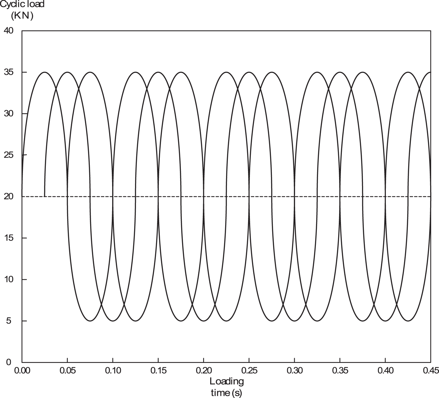
Sinusoidal reciprocating loads.
The fine ballast particle model constructed by inlaid composite particle units is shown in Fig. 6, and each ballast particle unit is composed of 2060 spheres. A three sleeper track broken box model is established by using fine ballast particles, and its dynamic process under cyclic load is calculated by discrete element method [7].
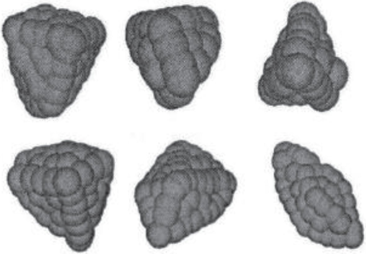
Fine ballast particle model.
As shown in Fig. 7, the relationship between the load on three sleepers and the settlement of sleepers under the action of 35 cycle loads. It can be seen from the figure that the settlement change of ballast can be roughly divided into two stages, namely, the initial settlement stage and the stable compaction stage. At the initial stage of loading, the sleeper settlement produced by the initial several loading cycles is large. With the increase of loading times, the ballast bed is further compacted, and the sleeper settlement produced by each cycle is gradually reduced. After a certain period of loading, the ballast bed reaches a stable and dense stage, that is to say, the sleeper settlement generated by each load is basically unchanged.
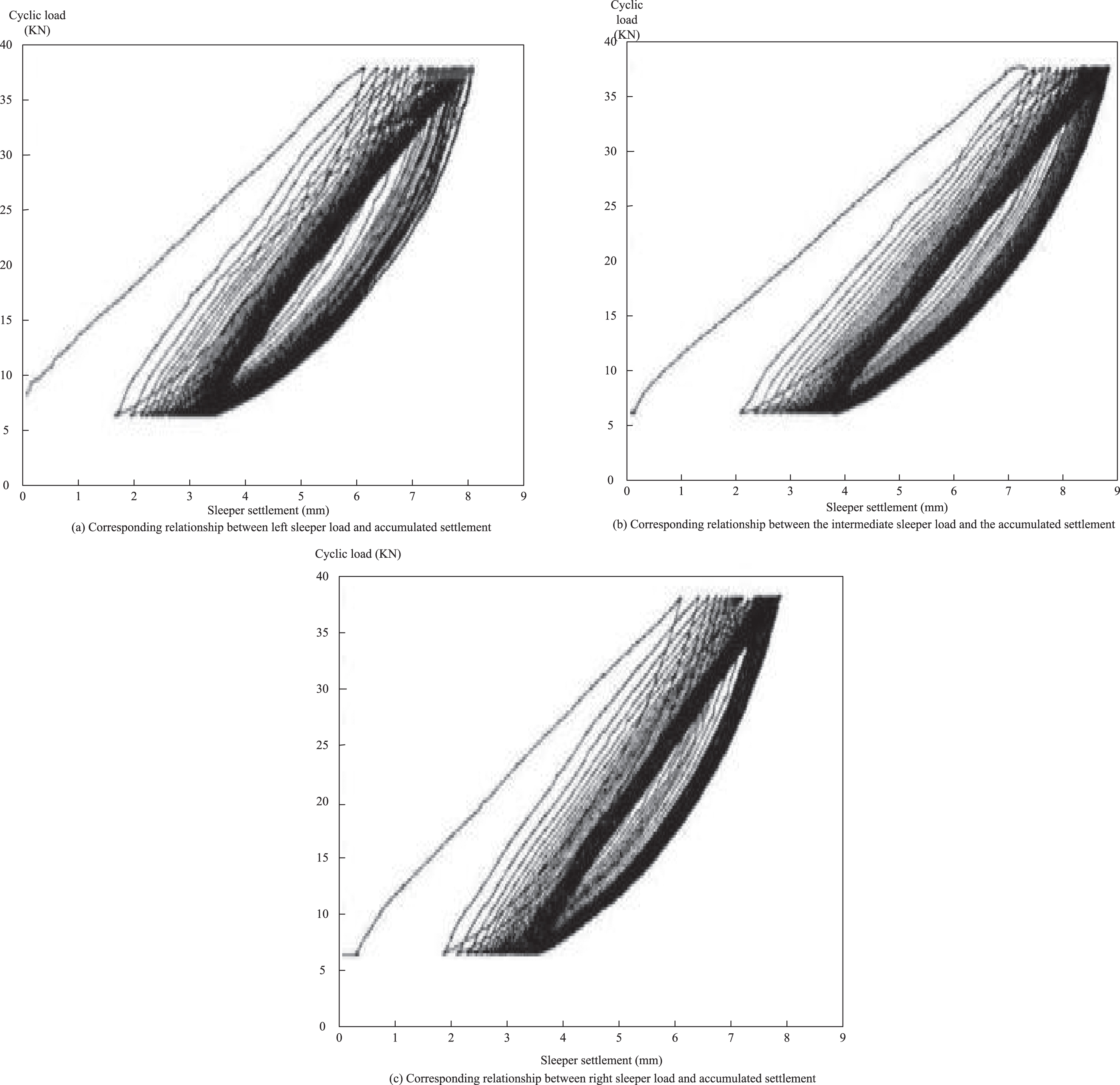
Diagram of load and sleeper settlement curve.
Figure 7 shows the relationship between the settlement of three sleepers and the loading times. It can be found that the settlement of the three sleepers has the same change trend as the cyclic load, showing periodic changes. The cumulative settlement of the three sleepers increases with the increase of the number of cyclic loads, but the growth trend tends to be gradual [10]. This is mainly due to the large gap between particles at the early stage of loading. Under the cyclic load, particles move with each other, the gap becomes smaller and arranged compactly. With the increase of loading times, its internal arrangement is continuously dense, so that its accumulated settlement tends to be stable [2].
The average value of the accumulated settlement u is fitted to the loading times N exponentially, and the change functions of the accumulated settlement of three sleepers are obtained, namely:
Figure 8 shows the final settlement of three sleepers after loading. After 35 cycles of loading, the accumulated settlement of the left sleeper is basically the same as that of the right sleeper, while the accumulated settlement of the middle sleeper is 0.56 mm and 0.44 mm smaller than that of the left sleeper and the right sleeper respectively. This is because the two sides of the ballast box model are rigid side walls, and the ballast on both sides has a squeezing effect on the track under the middle sleeper, which limits the settlement of the middle sleeper.
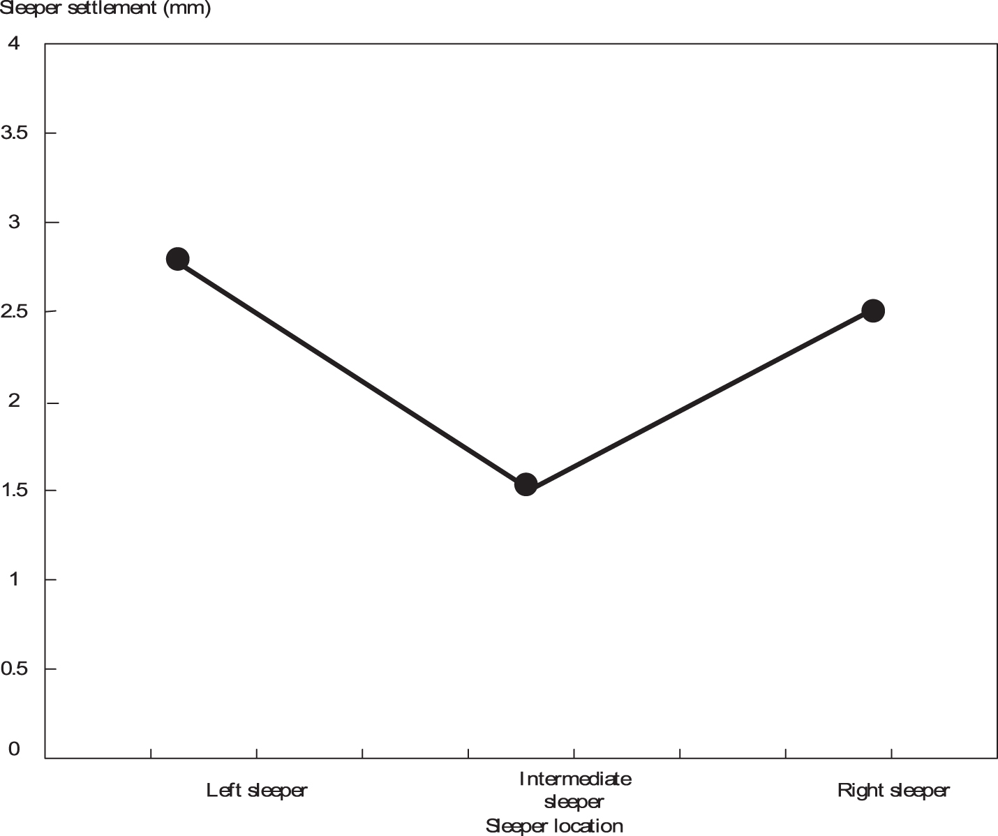
Final settlements of three sleepers.
Through the above process, the discrete element simulation of coupled vibration of high-speed railway track under load is realized, which provides effective support for the operation safety of high-speed railway.
The above process realizes the design of discrete element simulation method of high-speed railway track coupling vibration under load, but whether it can solve the problem of the existing method is uncertain, so the simulation contrast experiment is designed.
Indoor solid scale model of ballasted track
The experiment of coupled vibration and cumulative deformation of ballast bed under cyclic harmonic load was carried out in the rail transit laboratory. The 1 : 1 full-scale model of indoor ballasted track is designed and constructed in accordance with the design code and construction standards of China’s high-speed railway, with a longitudinal length of 8 m and a transverse width of 6 m. 60 kg/m rail, elastic strip V-shaped fastener and concrete type III sleeper are laid, with a spacing of 0.6 m, super ballast is adopted, with a thickness of 0.35 m under the sleeper, a slope ratio of 1 : 1.75, and a thickness of 0.7 m on the surface of the subgrade bed. The cross section is shown in Fig. 9.
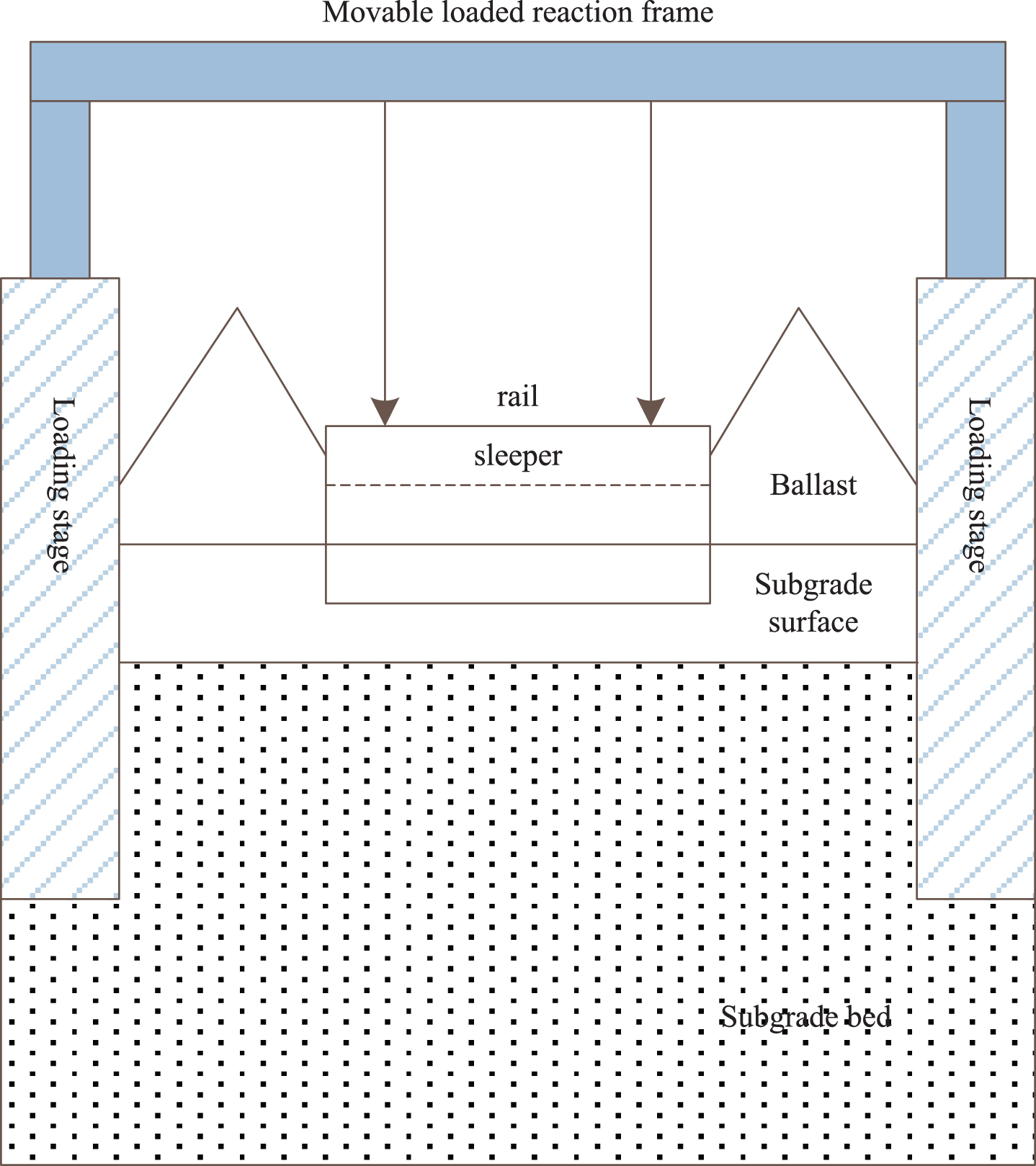
Cross section diagram of full scale model of ballasted track.
Figure 10 is the field diagram of the coupling vibration and deformation experiment of ballasted track. In order to simulate the dynamic load of the train, the loading frame is placed above the rail, and four supporting bases are symmetrically arranged at the bottom left and right of the loading frame. The longitudinal spacing of the supporting bases is 2.5 m (equal to the fixed wheelbase of the bogie of CRH2 EMU). Two hydraulic servo actuators are vertically installed between the loading frame and the reaction frame fixed on the ground. The maximum output load of the actuator is 500 kN. During the test, the output load of the two hydraulic servo actuators is set as the cyclic simple harmonic load with the same amplitude, frequency and phase, which is transmitted to the ballast bed through the loading frame, support base, rail and sleeper, so as to realize the simulation input of the load of the two wheel sets on the same bogie.

Field diagram of coupling vibration and deformation test of ballasted track.
Four measuring points are set on the sleeper and track bed directly below the loading frame support base. Install a displacement meter near the rail on the top of the sleeper to measure the vertical displacement response of the sleeper and record the change rule of the sleeper settlement with the number of load cycles. Three vibration acceleration sensors are respectively placed 50, 150 and 300 mm below the bottom of the sleeper to pick up the vibration acceleration response of the ballast under the simple harmonic load.
Among them, the schematic diagram of sleeper displacement meter is shown in Fig. 11.
Schematic diagram of sleeper displacement meter.
The comparison of simulation accuracy obtained through experiments is shown in Table 3.
Comparison of simulation accuracy
Comparison of simulation accuracy
According to Table 3, when the number of experiments is 10, the accuracy of the coupling vibration dynamic simulation method is 76%. The accuracy of the coupling vibration volume force simulation method is 59%, and the accuracy of the coupling vibration finite element simulation method is 56%. The accuracy of the method is 89%. At this time, the accuracy of this method is the best. With the increase of the number of experiments, the accuracy of the coupling vibration dynamic simulation method is 70% when the number of experiments is 50. The accuracy of the coupling vibration volume force simulation method is 67%, and the accuracy of the coupling vibration finite element simulation method is 51%. The simulation accuracy of the proposed method is much higher than the existing three methods, and the maximum value is 93%.
The experimental results show that: compared with the existing discrete element simulation method of high-speed railway track coupled vibration under load, the proposed discrete element simulation method of high-speed railway track coupled vibration under load greatly improves the simulation accuracy, which fully shows that the proposed discrete element simulation method of high-speed railway track coupled vibration under load has better simulation effect.
In order to solve the problem of poor simulation accuracy of coupled track vibration of high-speed railway by traditional methods, a discrete element simulation method of coupled vibration of high-speed railway track under load is proposed. By establishing a parameterized model of the solid particle system, simulation and analysis of particle behavior are provided, which provides a platform for solving many comprehensive problems involving particles, structure, fluid, electromagnetic, and their coupling. The following conclusions are obtained through experiments. It can be known from the discrete element simulation method that the amount of sleeper settlement caused by the load remains unchanged. The method in this paper can effectively improve the simulation accuracy of coupled vibration of high-speed railway tracks. The method in this paper has the best accuracy in many experiments. The simulation accuracy of the coupled element discrete element simulation method in the 100th experiment is as high as 93%.
When the discrete element simulation method is used to simulate the coupled vibration of a high-speed railway track, the simulation accuracy is greatly improved, but the simulation accuracy still has a large room for improvement, and it will be further researched and optimized in the future.