
Abstract
Gradually, OLED all screen has become one of mainstream mobile display devices. In this technology, the metal wiring in the bending area is prone to breakage, thus forming dead pixels. The yield rate may be affected by it. Therefore, the stress-strain analysis for the bending area in the bending process has become one of the main problems in OLED research. Firstly, the structural characteristics of OLED were analyzed, and the bending technology was introduced and analyzed. Secondly, the test process of discrete element method was analyzed. Finally, the strain analysis model was established through the multi-layer stacking characteristics of bending area. Moreover, the simulation of bending process was completed by quasi-static analysis. Then, the validity of analysis was verified by the test comparison. The results show that the proposed method can not only analyze the mechanical properties of OLED bending area effectively under different cover plate stiffness, and the maximum error rate of the method is only 4.87, which is far lower than the traditional method. Therefore, the content and conclusion provide the further research of mechanical properties of OLED bending area with an important technical foundation.
Introduction
Compared with the traditional screens, the foldable screen has high flexibility. Based on the appropriate interaction mode, different sizes of screens can be adopted according to various needs. At present, the realization of foldable screen is inseparable from the application of OLED technology (Organic light emitting diodes). OLED is ultrathin and self luminous. Meanwhile, it has the advantages of organic material, plane structure, and low temperature manufacturing process. In addition, it is compatible with plastic substrate, which makes the manufacturing of flexible OLED possible [1, 15]. However, there is a big problem in the process of OLED screen application. In the process of bending back the connecting area of panels, in order to increase the occupation ratio of screen, it is easy to lead to the metal wiring fracture and bad points, and thus to affect the yield rate. Therefore, it has great practical significance to research the stress-strain distribution in the bending area for optimizing the multi-layer stacked structure screen and reducing the bad points [18].
At present, there are three commonly used methods to analyze the mechanical properties of OLED bending area, including finite difference method (FDM), boundary element method (BEM) and finite element method (FEM). The former basic principle is to show two or more variables through the form of functions. From the mathematical perspective, the finite difference method replaces the differential equation with the difference, and transforms the differential equation into the algebraic equation, and thus to expand the application scope of mechanical calculation. The finite difference method has unique advantages in solving the problem of regular region. For the component with complex geometry, its calculation accuracy is greatly reduced. The boundary element method (BEM) can reduce the order of the problem to be solved, so as to reduce the space dimension to be processed. Meanwhile, this method can simplify the input parameters greatly and make the mesh division and readjustment more convenient, so that BEM can greatly shorten the calculation time and reduce the workload. Due to low solution efficiency of dense matrix, the solution scale is relatively small. The finite element method divides the continuous medium into some finite elements for numerical analysis. By discretizing the continuum, the difference function is established on each element, so that the function on the whole solution area is established. After that, the stress component is calculated by node displacement. The finite element method has the best generality and highest efficiency in solving problems. Currently, this method is widely applied in the engineering, but its floatability of accuracy is relatively high [4].
To solve these problems, in order to effectively analyze the mechanical properties of OLED bending area and improve the accuracy of stress test results, this paper uses a new method to test and analyze the mechanical properties of OLED bending area [8]. The results show that compared with the traditional method, this method can get the stress distribution of OLED bending area more clearly, which provides an important reference for the design of flexible OLED screen structure, the selection of materials and the solution of mechanical problems in bending process.
Basic definitions
OLED (Organic Light-Emitting Diode) is the abbreviation of organic light-emitting diode, which is called Organic Electro-Luminescence Display. In 1983, Chinese American Professor Deng Qingyun found OLED in the laboratory and then researched on it. In 1987, Professor Deng Qingyun and Van Slyke adopted ultrathin film technology, and used transparent conductive film as the anode and took Alq3 as the light-emitting layer, and used the triarylamine as hole transport layer, Mg/Ag alloy as the cathode, and thus to make the double-layer organic light-emitting device. In 1990, Burroughes discovered OLED taking the conjugated polymer PPV as the light-emitting layer. From then on, there has been a worldwide upsurge in OLED research. Professor Deng is also known as the “father of OLED [13]. OLED is a kind of electroluminescent device based on multilayer organic film structure. It only needs the low driving voltage. These characteristics make OLED very prominent in the application of flat panel display.
OLED bending area is connected with display area and control circuit, which is bent in two when we use it. The OLED display screen of Apple watch after disassembly is shown in Fig. 1.
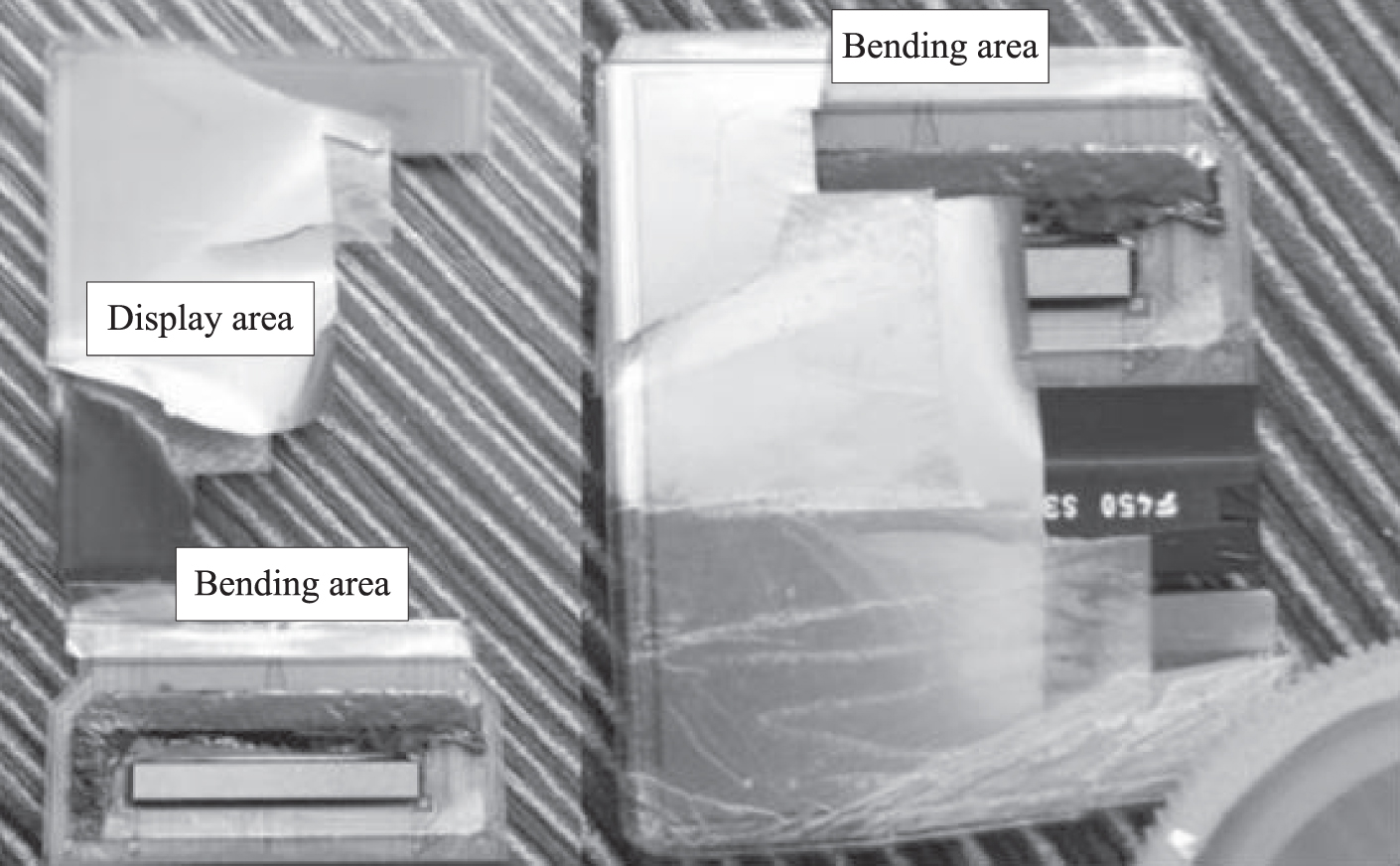
OLED bending area.
In the preparation process of OLED, different film materials are usually produced on the substrate with the help of PECVD, Plasma Enhanced Chemical Vapor Deposition (PECVD), showing the feature of multi-layer stacked “sandwich” structure. That is to say, there is an organic layer between the two electrodes. Indium tin oxide (ITO) is taken as the anode of OLED devices. HIL is the hole injection layer. HTL is the hole transport layer. EBL is the electronic barrier layer. EML is organic light-emitting layer. ETL is the electronic transmission layer. EIL is the electronic injection layer. Generally, the cathode metal is magnesium, aluminum and other metals [12].
In the process of bending, the materials in the bending area are gradually bent and thus to reach the folding state. In the process of increasing bending curvature, the material deformation is also increased, leading to the bending damage. The bending process of OLED bending area is shown in Fig. 2.
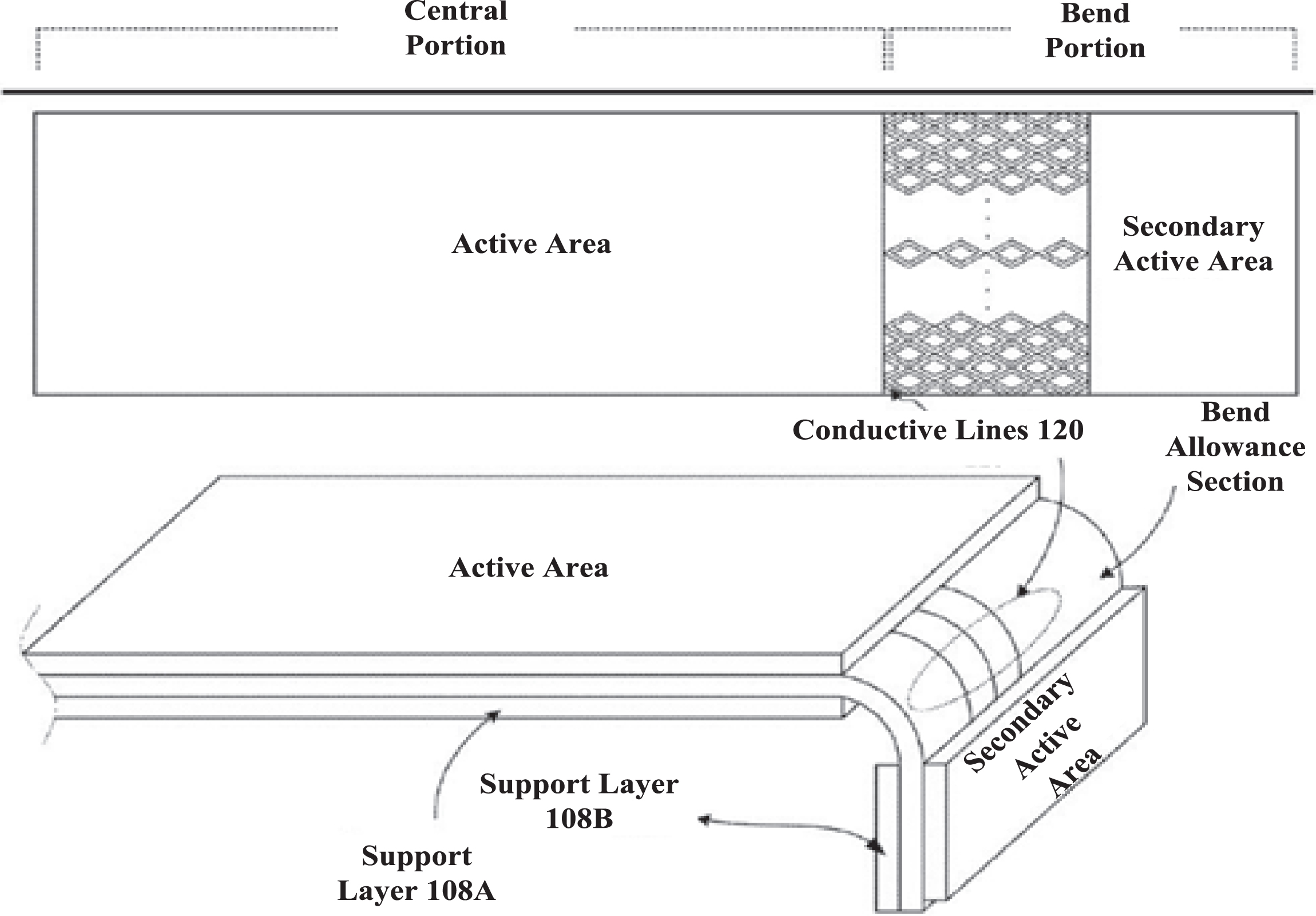
Schematic diagram of bending process in OLED bending area.
The foldable screen is composed of many material layers. When folding, if the materials are extruded, foldable screen is easily cracked by stress.
The stress refers to the internal force per unit area when the material is affected by external force and internal resistance force is generated. In order to realize this technology, it is necessary to prevent the material damage during the panel folding, including the control for stress between material and contact surface (folding area), the selection of appropriate basilar plate, the determination of the ideal stacked structure and the optimization of stripping process. All of them are the key challenges [2].
The discrete element method (DEM) is an effective numerical method to research the structure and mechanical behavior of block elements. Its basic principle is to regard the independent block material as a calculation unit. The relationship between the elements is determined by the contact model with clear physical significance. When the block element is influenced by the unbalanced force from other elements, it will move. According to Newton’s second law, the motion equation of a single element is established. The position of block in the system is updated by tracking the motion state of element [11]. The main feature of this method is the treatment for nonlinear contact between block elements, and the contact between block elements can be freely broken and formed. The specific calculation process is as follows: block element formation and element search in the initial preparation stage, time-step iterative algorithm of motion equation, contact judgment and contact force calculation during the cycle calculation. The program block diagram is shown in Fig. 3.
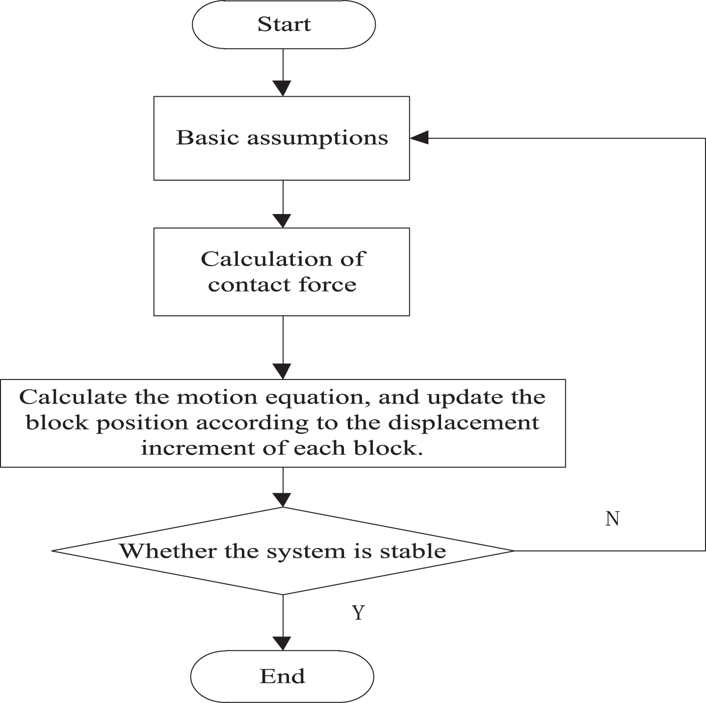
Test program block diagram of discrete element method.
The discrete element method is a numerical method based on explicit solution. This method is similar to other explicit calculations in time domain, such as the explicit difference scheme for solving parabolic partial differential equations. “Explicit solution” refers to the property of algebraic equations used in numerical calculation of a physical system. During the calculation of explicit method, the quantity on one side of the equation is known, while the quantity on the other side can be obtained by simple substitution method. This is different from the implicit method. The implicit method must solve simultaneous equations. When using the explicit method, we can assume that each block element only produces the force on its adjacent block element in each iteration time step, so that the time step must be small enough and thus to make the explicit method stable [5]. Because the matrix does not need to be formed when using the explicit method, large displacement and nonlinearity can be considered without additional time.
The basic assumptions for the discrete element are as follows: one, the block element is an ideal rigid body. The movement of each block is only the translation of space position and the rotation around the centroid. Its shape and size are unchanged; two, the contact between blocks is regarded as the angle-edge contact or edge-edge contact; three, the contact force between blocks is determined by the stiffness of joint surface, the relative displacement of contact point and the relevant damping force; four, when the block moves, the kinetic energy will be converted into the heat energy, and then it is dissipated, the viscous damping is introduced to absorb the kinetic energy, so that the system can be stable and a quasi-static solution can be obtained without any uncertain oscillation; five, the contact conditions between the blocks meet the non-tension and Mohr Coulomb criteria [9].
Basic equations of discrete element method
In the discrete element method, the medium is assumed to be a set of discrete blocks at first, so there is no constraint of deformation coordination between blocks, but the balance equation needs to satisfy:
As shown in Fig. 4 (a), there is a group of forces acting on a block A by edges and corners of adjacent blocks. As shown in Fig. 4 (b), if the gravity is considered, the self weights of Fx
i
, Fy
i
are also added. This group of forces will produce resultant force F and resultant moment M on the center of gravity. If the resultant force and resultant moment are not equal to zero, the unbalanced force and unbalanced moment make the block move according to the Newton’s second law F = ma and
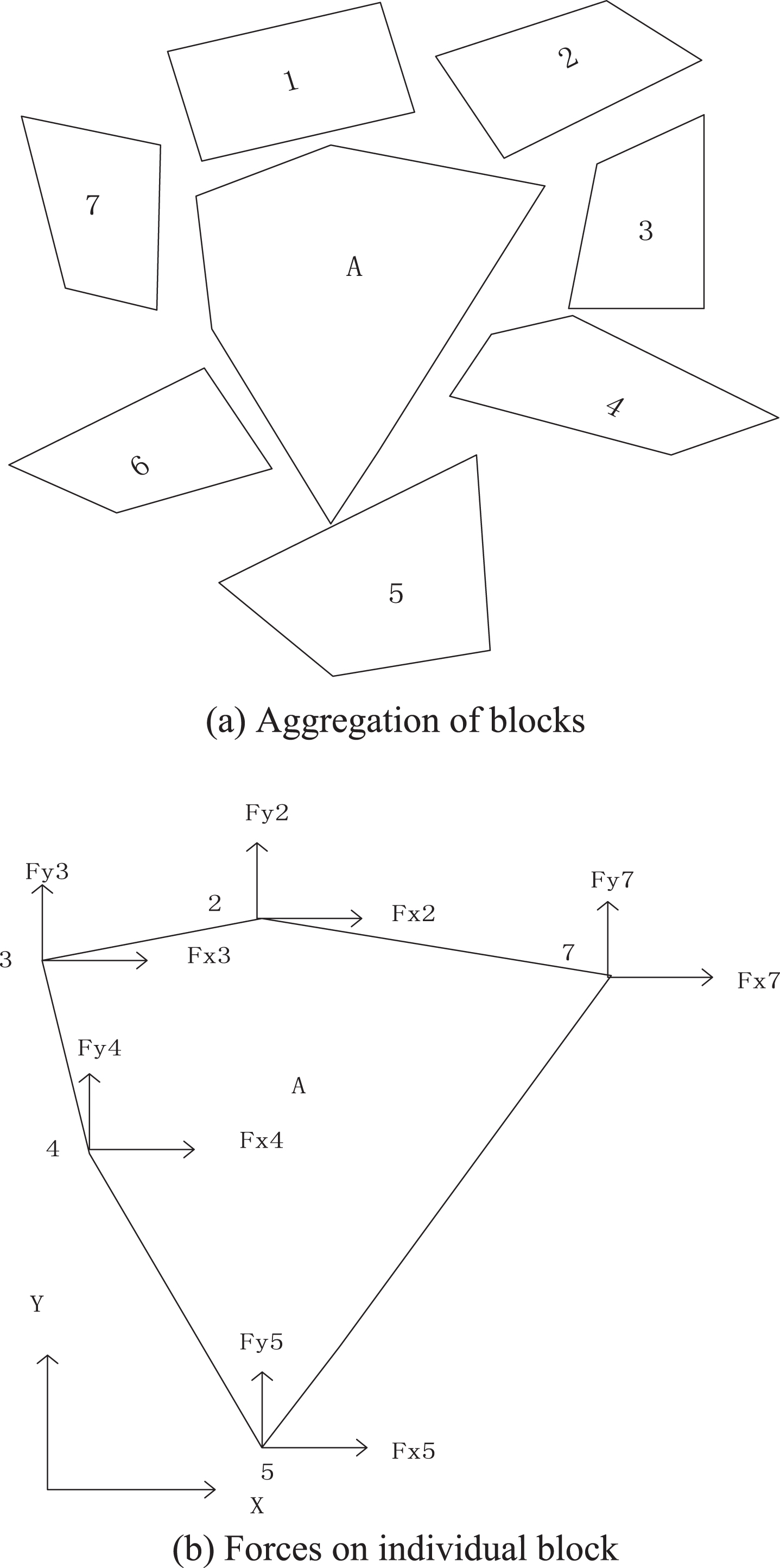
Aggregation of blocks and forces acting on individual block.
Supposing that the normal force between blocks is set as F
n
, this is directly proportional to the normal “superposition u
n
” between them. Thus:
In the formula, d n is the normal stiffness coefficient.
The so-called “superposition” is a quantity assumed in calculation, if it is multiplied by a scale coefficient, we can use it as a kind of measure of normal force. For example, we can increase the value d n and decrease u n to represent the equal normal force.
If the boundaries of two discrete elements overlap, there are two corner points in contact with the interface, and then the force at both ends of interface can be used to replace the force on that interface. Of course, the actual situation of interface contact is far more complex than the two-corner contact mode. It is impossible to determine which points are in contact, so the simplest “interface superposition” mode based on two-corner contact is adopted [10].
Because the shear force of block is related to the history or way of block movement and block loading, the shear force should be expressed by increment ΔF
s
. If the relative displacement between two blocks is Δu
s
, thus:
In the formula, d s is the shear stiffness coefficient of the joint.
In Equation (1) and Equation (2), the relationship between force and displacement is elastic. In some cases, the elastic relationship is not tenable. It is necessary to consider the failure conditions. For example, when the rock block is separated by tension, the normal force and shear force on the surface of rock block disappear immediately. In the case of plastic shear failure, it is necessary to check whether the shear force F s exceeds E + F n tan β in each iteration. E is the cohesive force. β is the internal friction angle. If it exceeds E + F n tan β, there is a sliding between blocks. At this time, the shear force takes the limit value E + F n tan β. That is the Mohr-Coulomb criterion.
According to the geometry of rocks and the relationship with the adjacent rocks, a group of forces acting on a specific rock can be calculated by the above principle. It is not difficult to calculate their resultant force and resultant moment of resultant force by this group of forces. Meanwhile, the acceleration and angular acceleration of the mass center can be determined according to Newton’s second law, and thus to determine the velocity, angular acceleration, displacement and rotation within time step Δt [3].
For example, there is acceleration
In the formula, F x is the resultant force of direction x; h is the mass of rock block.
The velocity
In formulas, t0 is the starting time and Δt is the time step. t1 = t0 + Δt, for the movement and rotation of block along y direction, there are similar formulas.
The discrete element method includes the static relaxation method and dynamic relaxation method. As a method of solving simultaneous equations, the relaxation method has an important application in mechanics. The relaxation method refers to the solution method of block displacement. The fundamental difference between static relaxation method and dynamic relaxation method is that the solution methods of block displacement are different [20]. As everyone knows, the dynamic relaxation method is based on Newton’s second law. The solution format (acceleration⟶speed⟶displacement) makes the introduction of damping coefficient and time factor inevitable, leading to a series of problems such as system oscillation control or accelerating convergence speed. In contrast, the static relaxation rule is relatively simple. According to the force-displacement relationship when the block producing the unbalanced force achieves a rebalancing, the set of balance equations is established, and the displacement of block is implicitly solved by the set of equations [14–16]. The static relaxation method avoids many disadvantages of dynamic relaxation method in solving displacement. Its cost is only to introduce a 6×6 linear equation group. The calculation cycle of the two relaxation methods is shown in Fig. 5.
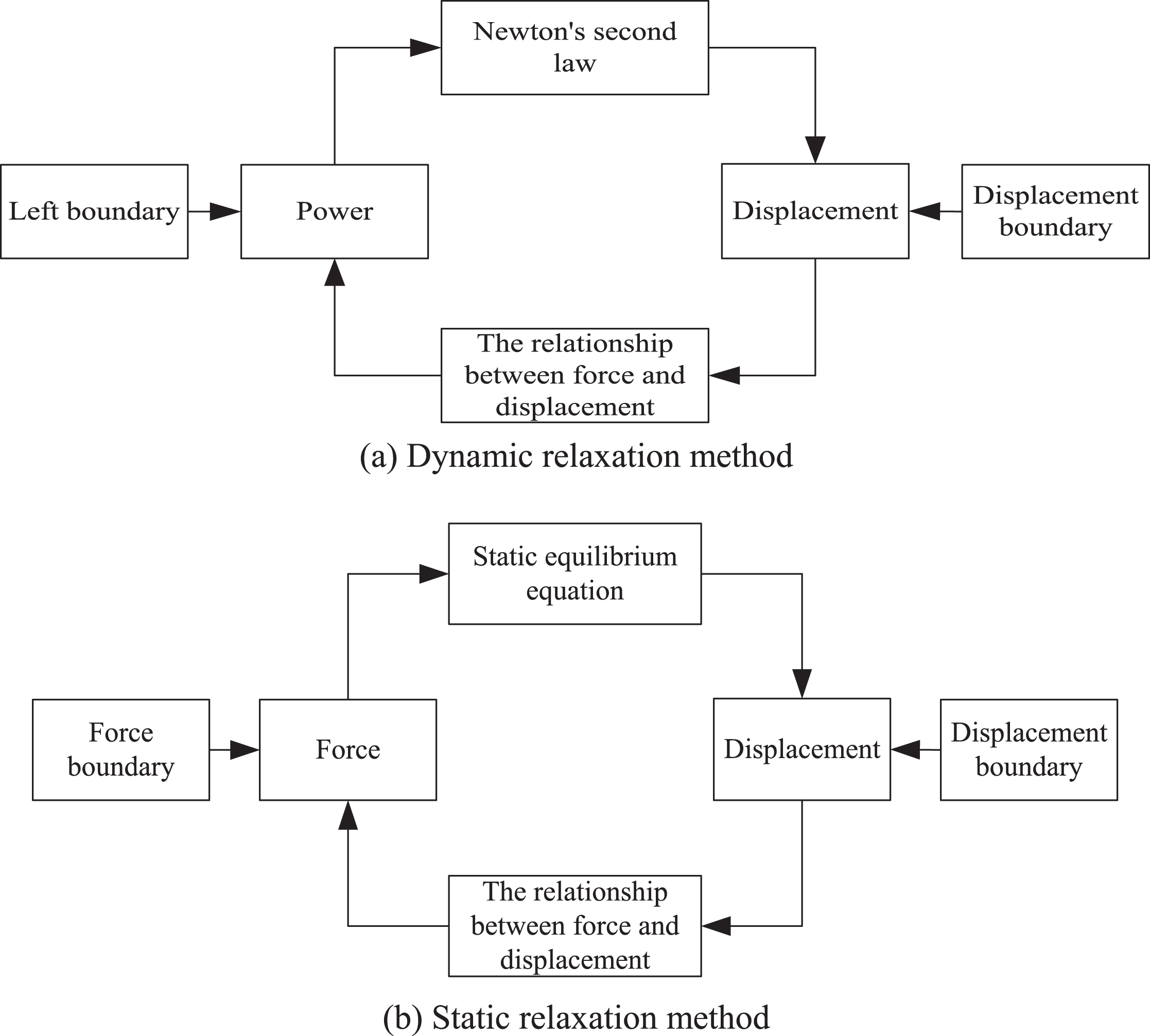
Calculation cycle of the two relaxation methods.
The dynamic relaxation method is a numerical method which changes the nonlinear static problem into the dynamic solution. The essence is to integrate the critical damping vibration equation step by step [6]. In order to find the quasi-static solution, the mass damping and stiffness damping are introduced to absorb the kinetic energy form system. When the damping is less than the critical value, the vibration of system disappears quickly and the block system converges to the quasi-static value.
The basic motion equation of dynamic relaxation discrete element method is:
Where, k is the mass of element; V is the displacement; t is the time; g is the viscous damping coefficient; b is the stiffness coefficient; f is the external load.
The static relaxation discrete element method is to directly find the relationship between force and displacement when the block loses balance, so that the implicit method is used to solve the simultaneous balance equations. Meanwhile, this method takes the complete elimination for the residual force and moment of block as the goal of iterative solution.
The general expression of simultaneous equilibrium equations of the static relaxation discrete element method is:
Where, Δx, Δy and Δz are displacements of the centroid of block unit;
Taking the bending equipment of a Korean OLED manufacturing equipment supplier (AVACO) as an example, the discrete element method is adopted to analyze the stress of OLED bending area. The geometry model of AVACO bending equipment is shown in Fig. 6.
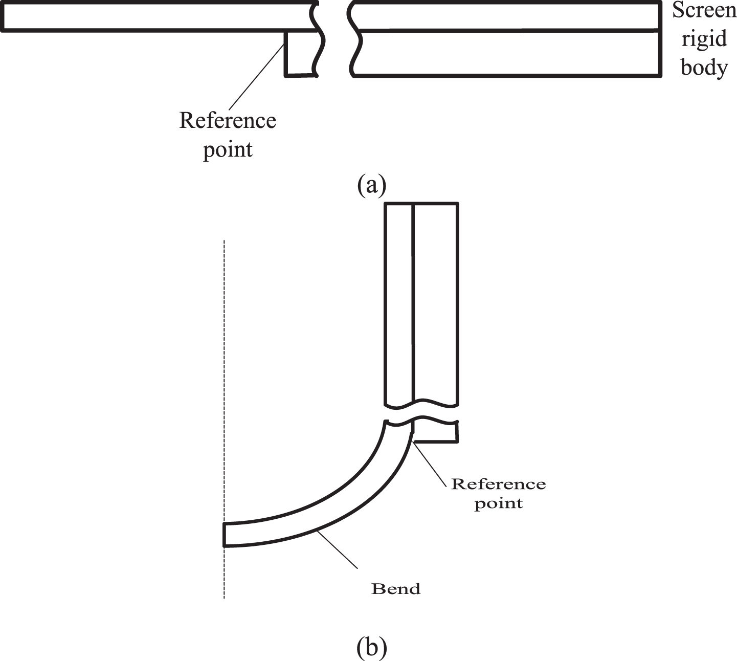
Geometric model of AVACO bending equipment.
When bending, the rotation of rigid body drives the screen to be bent. In order to make the bending part form an arc and thus to minimize the stress, the distance between the symmetry axis and the reference point is set as π4 R. When the radius is 5 mm, the distance is 7.85 mm [7]. In addition, the reference point needs to move to the left (π 4-1) R, 2.85 mm, and finally it reaches the position in Fig. 6 (b). The screen structure is composed of protection cover plate, OCA, touch layer, polarizer, display layer, base plate and back plate. The material information of each layer is shown in Table 1.
Thickness and material information of each layer of screen
In this article, abaqus is used to simplify the simulation model into a problem about two-dimensional plane strain. The boundary conditions are given. In the first 1 s, the rigid body rotates anticlockwise around the reference point. The rotation speed is 1.57 rad/s. At the same time, it moves to the left, and the speed is 2.85 mm/s. Then, it is placed for 300 s and thus to be close to the actual use [17, 19].
In the deformation process of OLED bending area, the two main stages of bending area: (1) bending in half, bending form straight state to semicircle state; (2) pressing down from semicircle to semiellipse state. According to the structural characteristics and loading characteristics of the bending area, 1/4 model of a single metal wire can be adopted. The modeling is completed in Hypermesh 2017. As shown in Fig. 7:
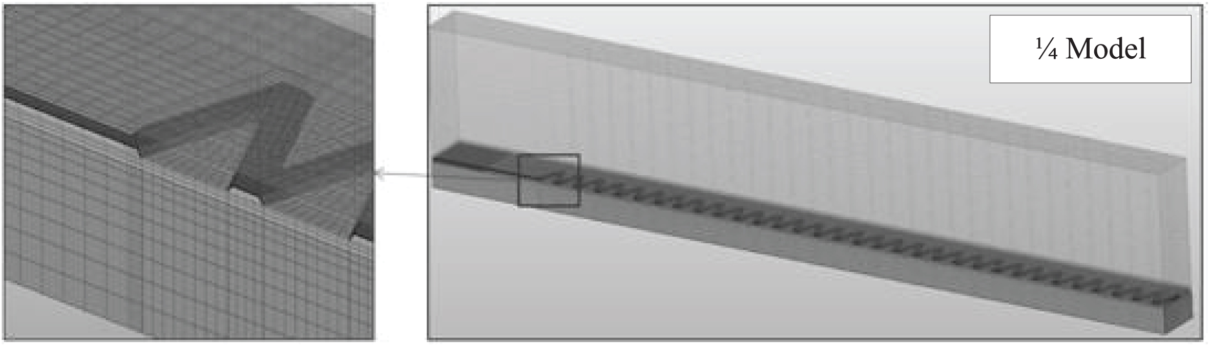
Quarter discrete element model of single metal wire in bending area.
The analysis model is partition by tetrahedral mesh. The length is 0.025 mm. All structures in thickness direction are divided into three layers. The type of grid unit contains the plane strain, the hybrid element and reduced integral element, which are shown in Fig. 8.
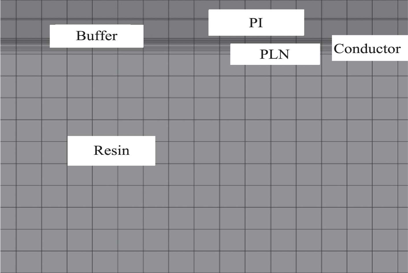
Overlay mesh generation of bending area.
According Table 1 and Fig. 8, the thickness of display layer is 10μm. During the bending analysis, the unit is in a state of bending, and more integration points need to be deployed in the thickness direction, so that more accurate results can be obtained. Generally, it can be divided into three or four parts along the thickness direction, but that will lead to high-density element and low calculation efficiency. Therefore, this paper uses the thick shell element (T-shell) to simulate, so that only one layer can be adopted. Meanwhile, more integration points can be deployed in the thickness direction to give consideration to the calculation efficiency and accuracy. The quasi-static implicit solution is adopted for analysis. The solver is Ansys 19.0. The second end is regarded as the constraint end, which is used to limit the normal displacement (z direction) and vertical displacement (y direction) of bottom node. The first end uses displacement loading method to stiffen the end plane. the point-surface contact is used to achieve MPC connection of Pilot node-surface. Finally, the displacement loading of 90° rotation is added to Pilot node. See Fig. 9.
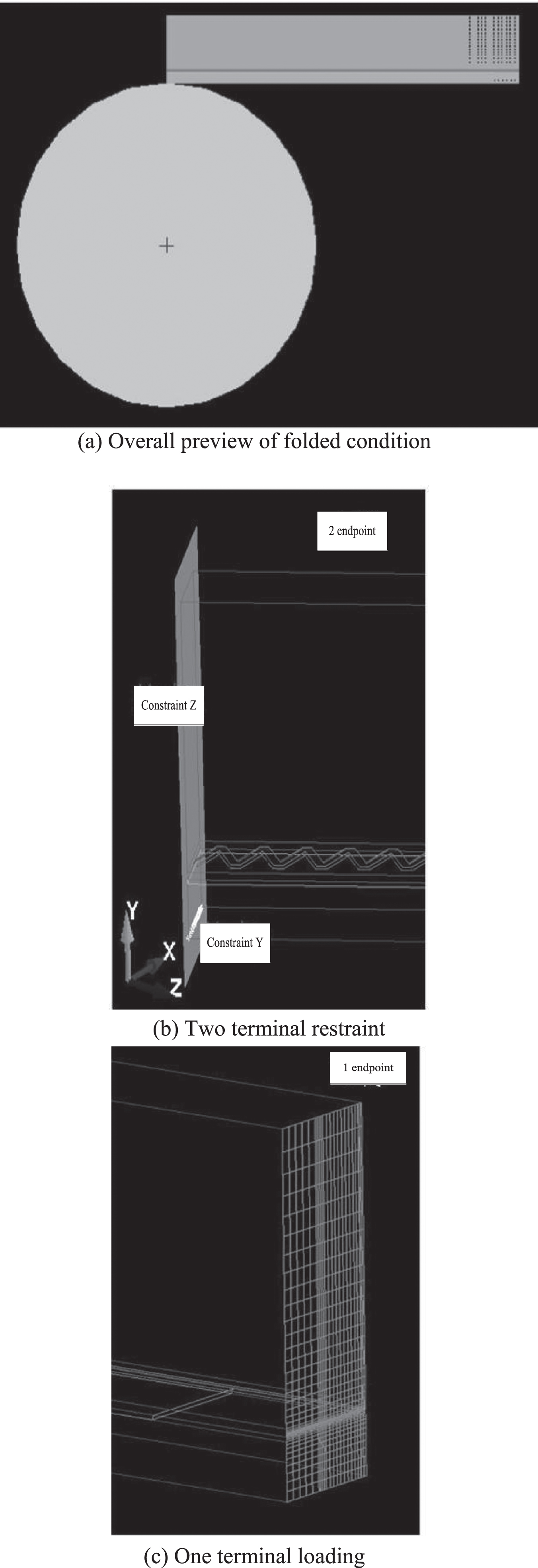
Boundary condition of bending condition.
Stress under different rigidities of protective cover plate
The protective cover plate belongs to the film layer which is easy to be adjusted in the flexible screen structure. On this basis, the material parameters of protective cover plate were adjusted to analyze the influence of its stiffness on the stressstrain. The results are shown in Fig. 10.

Stress under different rigidities of protective cover plate.
Figure 10 shows that when the rigidity of protective cover plate is increased from 2.5 Gpa to 55 Gpa, the stress neutral layer at the display layer is basically unchanged, but the strain of each OCA layer is increased.
Commonly, the backplane is at the bottom of flexible screen, which plays a role in protecting and supporting for optical devices. Therefore, it is necessary to discuss the influence of backplate on the neutral layer at display layer. The back plates with thickness of 25μm, 50μm, 75μm, 100μm and 125μm are chosen for comparative analysis. The results are shown in Fig. 11.

Stress under different thickness of back plate.
Figure 11 shows that when the thickness of back plate increases from 25μm to 125μm, the stress neutral layer of display layer moves down, and the strain of OCA adhesive layer next to it will increase.
The bending radius of flexible OLED screen must be considered during the design. When researching on the influence of bending radius on the screen, the radius of 3 mm, 4 mm, 5 mm, 6 mm and 7 mm are compared, and the results are shown in Fig. 12.
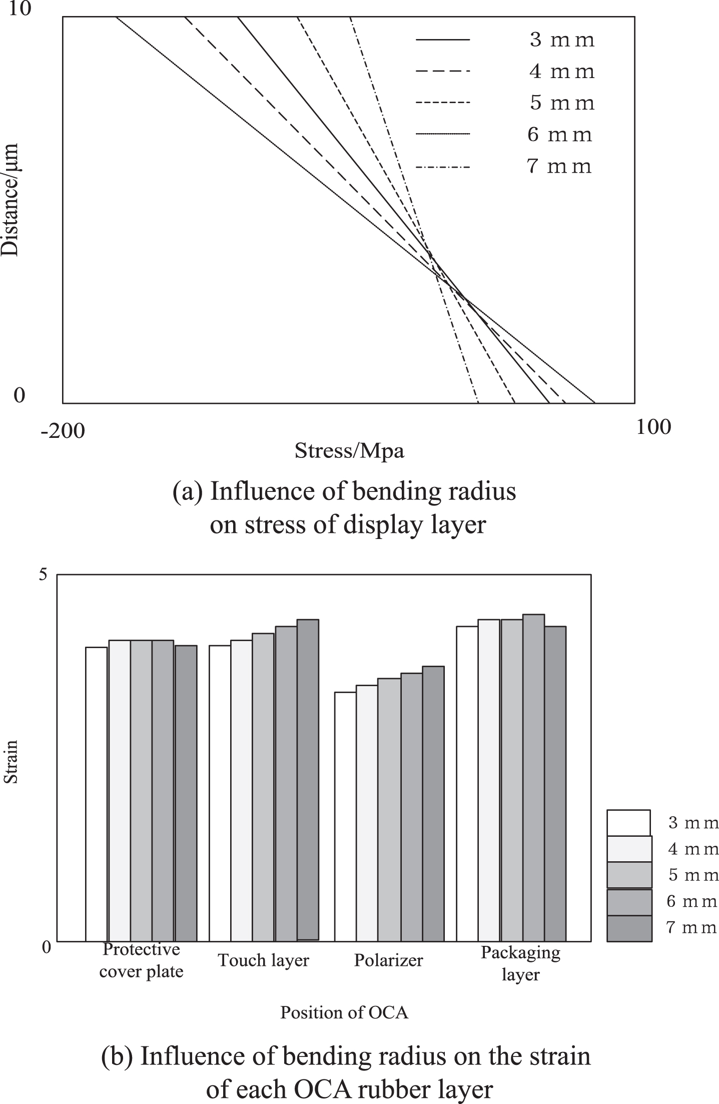
Stress under different bending radius.
When the bending radius increases from 3 mm to 7 mm, the stress of display layer decreases obviously, and the strain change of OCA rubber layer is not significant.
In conclusions, properly reducing the rigidity of protective cover plate and the thickness of back plate is conducive to improving the peeling phenomenon of adhesive layer. Increasing the thickness of back plate is conducive to reducing the tensile stress of display layer. Increasing the bending radius is conducive to optimizing the overall stress of structure, which can play a protective role in the display layer.
The load with 455 torque and 4r/min rotational speed is added to OLED, and then the stress in OLED bending area of is calculated by the proposed method, the finite difference method (FDM), the boundary element method (BEM) and the finite element method (FEM). In order to facilitate analysis, the error rate p is defined as:
In Equation (8), A is the test value, and B is the actual value.
From the Table 2, it can be seen that the error rate of this method after five calculations is within 5%, and the maximum error rate is only 4.87, while the maximum error rate of FDM method is 8.69, the maximum error rate of BEM method is 12.32, and the maximum error rate of FEM method is 6.58. It can be seen from the analysis of the above data that the error rate of the stress analysis result obtained by this method is far lower than that of the traditional method, which shows that the method in this paper is far lower The accuracy of this method is higher and the result is more reliable, which fully verifies the effectiveness and superiority of this method.
Results of stress comparative analysis
When the flexible OLED screen is folded along a central line, the optical transparent conductive resin layer is easy to be peeled off, and each film layer includes the stress neutral layer. That is the position where the stressstrain is zero. The optical components at the display layer are most likely to be damaged. Therefore, this paper analyzes the mechanical properties of OLED bending area based on the discrete element method, and then compares it with three methods such as the finite difference method (FDM), the boundary element method (BEM) and the finite element method (FEM). The results show that the different rigidity of cover plate does not influence the position of stress neutral layer at the display layer. With the increase of thickness of back plate, the position of stress neutral layer at the display layer will move down. If the bending radius increases, the structural stress will decrease. The decrease of the rigidity of cover plate and the thickness of back plate are beneficial to the decrease of strain of OCA adhesive layer. And the contrast result show that the maximum error rate of the method is only 4.87, which is far lower than that of the traditional method. It shows that the method is more accurate, which provides a reference for the mechanical problems in the bending process of the flexible OLED screen. However, this method does not take into account the cost of time, and the test time is long. Next, we will further optimize this method to shorten the test time.