
Abstract
An isolated network with Wind Turbine implemented by Double Fed Induction Generator (WTDFIG) that maintaining different electrical variables in safe ranges following a severe transient condition is always a serious challenge. This paper proposes a control scheme based on Auto-Tuning Fuzzy PI (ATFPI) concept for the Rotor Side Converter (RSC) of the DFIG by online tuning of the output scaling factor of the ATFPI for enhancement the transient behavior of the system under various condition of operation. The scheme includes a coordinator unit which is elaborated to effectively regulate the frequency and active power of the system. The performance of the proposed ATFPI controller is evaluated in a typical network in Matlab Simulink environment. Obtained results show that the control can successfully meet all functions drawn in the scope and easily put behind the conventional competitors like conventional PI and/or fuzzy PI controllers.
Keywords
Introduction
Todays, the need for electrical energy is continuously increased and renewable energy sources such as wind are widely and simultaneously used to generate the electrical energy [1, 2]. The Wind Energy Conversion System (WECS) is more economical and efficient in comparison with other renewable sources. When the input source of energy to WECSs is variable, the variable speed WECSs have higher efficiency compared to constant speed WECSs [3]. However, the dynamic impacts of such generations on the system performances is always a serious concern that must be studied carefully [4]. In the current researches, one of the important subject in this area is addressed to isolated WECS.
Many isolated systems utilize diesel-generator to generate the electrical energy. The use of diesel-generators leads to increase the cost of the produced energy and the pollution of environment [5]. Hence, for reducing the dependency to fuel of diesel-generator the solutions based on wind generation and energy storage have been proposed in the past decade [6]. For using of wind energy as an isolated application, two subjects are needed as follow: i) association of the energy storage into the WECS is an effective factor for reducing fluctuations of the power, therefore, determination of capacity of energy storage system is important in an isolated WECS for a proper and secure operation, ii) the selection of suitable control method is another subject in an isolated system [7, 8] which is the main purpose of this paper. The WTDFIG is widely used for variable-speed wind turbine, and it is one of the most important generators for WECSs [9, 10]. The DFIG is also used for isolated operation such as wind applications. Some published papers are presented in [11], which have concentrated on the DFIG as generator for isolated WECS applications. These documents describe modeling and control techniques used for an isolated WECS with DFIG.
The study of behavior of an isolated system in transient condition and recovery of a system subjected to a disturbance is an important aspect in the operation of the system. Here, for the study of performance of the isolated system in this condition, the analysis tool is used based on the time domain simulation method. The transient operating characteristics of the WECS with DFIG in the grid connected mode have been studied by researchers [12]. Since the rotor speed of the wind turbine and its fluctuations are affected by the wind velocity variations and the pulsating input torque to vertical axis of the generator, hence, there is an amount oscillation in the magnitude and frequency of the generator terminal voltage and current [13]. An efficient and fast scheme for frequency regulation in an isolated WECS is presented in [14] and proposed a scheme consists of four sub-schemes with the main function of compensating for the frequency fluctuations, which is a consequence of wind and load variations. Several papers also attempt to study the impact of the WECS with the DFIG on the power system stability by modelling of all components of a case study system [15–17]. The dynamic behavior of the DFIG will be more important at periods of various transient conditions such load changes, switching operation and fault occurrence in the network. This behavior is properly known and it has been modeled and investigated in transient studies [18].
The isolated WECS with DFIG is a nonlinear system that operates in a continuously changing environment e.g.; loads, DFIG inputs/outputs, topology, and operating key parameters. When it is subjected to a transient disturbance, the stability of the system depends on the nature of the disturbance as well as the initial operating condition may be lost. In this condition, the isolated system must be able to response the load demand satisfactorily. In isolated applications of DFIG, the frequency and voltage of the network must be adjusted by some reliable methods. In such cases, a more complex control is needed in order to reach this aim [15, 18]. So inaccuracy in designing and tuning of controllers may lead to stability problems of the system. Controllers can improve the performance of the isolated WECS in transient conditions. Poorly tuned controller gains of WTDFIG may cause of instability of control modes. It is hard to regulate the gain of controllers so that it provides a suitable damping for the stability of the system. Therefore, in any operating conditions of isolated WECS with DFIG, the Rotor Side Convertor (RSC) controller and Grid Side Converter (GSC) controller can have important role in maintaining the stability of the voltage and frequency of the network. According to nonlinear characteristics of the isolated WECS with DFIG, the performance of a conventional PI (CPI) by fixed gains in RSC and GSC controllers may be poor due to overshoot and oscillation of output parameters of the system [19].
Recently, Fuzzy Controllers (FCs) are considered for process control applications. The FC does not need a detailed mathematical model of the system and its behavior is decided by a set of rules. Therefore, it is easy to implement and the similar performance is expected from FC compared to conventional controller [20, 21]. Among various FCs, the PI-type FC is most common and practical. In [22] the dynamic response of DFIG based wind farm during remote fault condition and after the clearance of fault is analyzed using the proposed fuzzy logic controller. The behavior of the fuzzy logic controller is compared with PI controller. In addition, the Fuzzy Proportional Integral (FPI) control is widely considered in various power systems applications [23, 24]. In [17] a grid connected WTDFIG system is selected for study in transient conditions and the FPI controller is used in the RSC and GSC of the DFIG while the input and output gains of the FPI are assumed to be constant. Since, four FPI controllers are applied in the RSC and GSC of the DFIG, the simulation time would be significantly increased.
The FPI controller can be easily implemented in practical systems [25]. Moreover, it is not sensitive to the variations of the system structure, parameters and operating points. The CPI controller needs adjusting to achieve a fast and dynamically acceptable actions [26, 27]. In common FC, it is usually considered the nonlinear characteristics of the system by limited rules to create the necessary control performances. In such condition, the common FCs with fixed value of output/input Scaling Factors (SFs) and simple membership Functions (MFs) may not be suitable for access the desired control performance [28, 29].
In this paper, an ATFPI controller is presented to manage the transient conditions of an isolated system equipped with WTDFIG. In addition, it is concentrated on the tuning of the output SF (similar to gain of a controller) because of its strong impact on the stability of the system. The initial values of the parameters of ATFPI controller (it is calculated by Ziegler-Nichols method) are modified online by fuzzy rules according to variation of the system parameters. The output SF of the ATFPI controller is continuously tuned in each instance by gain of (k). The ATFPI controller is also able to eliminate large overshoots and excessive oscillations caused by the integral operation in the PI part of the controller, through variable gain of (k). Moreover, the proposed scheme employs a coordinator that manages power consumption of the main load and power generated by the WTDFIG, the Local Energy Storage (LES) and the pitch angle controller. The control strategy and the active power coordinator signals regulate the frequency and voltage of the isolated WECS with the DFIG to improve various transient conditions. Two CPI controllers of RSC of DFIG are replaced by the ATFPI controller in different arrangements. The performance of the ATFPI controller is compared with the CPI from several viewpoints such as Percent of Over-Shoot (POS), Rise Time (RT), Settling Time (ST), Steady State Error (SSE), Integral Squared Error (ISE), Integral Absolute Error (IAE), Integral Time-weighted Squared Error (ITSE), and Integral Time-weighted Absolute Error (ITAE) to show the superiority of the proposed control scheme.
This paper is organized as follows: in Section 2, the description of operation of the WTDFIG in isolated mode, mathematical models of the DFIG, the RSC and the coordination method of active power of the isolated system are presented. The ATFPI control strategy is fully described in Section 3. The isolated WECS equipped with a DFIG based on the purposed ATFPI controller is evaluated in various transient conditions in section 4. Finally, section 5 concludes the main points of the paper.
Isolated system with DFIG wind turbine
A general view of a typical isolated WECS system is shown in Fig. 1. This isolated system includes: WTDFIG unit, Local Energy Storage system (LES), Auxiliary Load (AL), the Diesel Generator System (DGS), and the main load which is assumed to be symmetrical constant impedance. The required reactive power is generated by the GSC whose DC voltage is supported by a LES. The frequency of the DFIG and the direction of the reactive power is governed by the RSC, while the GSC adjusts the DC link voltage [30]. The DGS is connected when the existing resources are not able to provide enough active and reactive powers for the isolated system and activated when the DFIG is rotating at sub-synchronous speeds. On the other hand, if the reactive power supplied by the DFIG is less than the required reactive power then the DGS can operate as a synchronous condenser.
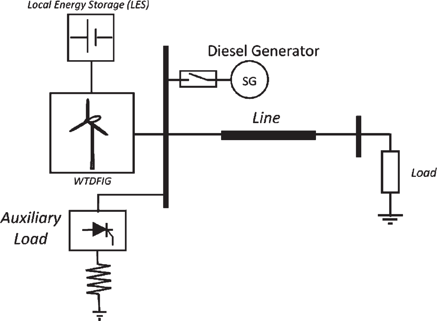
Typical Isolated WCES with DFIG.
The main load depending on its characteristics effects on voltage and frequency changes and vice versa. However, the range of voltage and frequency oscillations of the network depends on the nature of disturbances and characteristics of loads. This issue becomes more important if the network is isolated. The unexpected lack of load often leads to high frequency and voltage conditions and loss of generation and system collapse due to excessive rise of load usually lead to low frequency and low voltage conditions. Moreover, a limited short circuit fault often leads to a severe voltage depressions followed by oscillations in voltages and frequency.
Here, the battery can behave as a fixed voltage load, and it is charged/discharged through the dc link of the DFIG. In low speed condition of wind, the WTDFIG is isolated from the system and the load is fed directly by DGs and the battery through the GSC of the DFIG proportional to their capacity. When speed of the shaft of the WTDFIG is higher than the synchronous speed, the WTDFIG supplies the load and the additional energy is used to charge the battery through the RSC. If the battery being fully charged and the pitch regulation unable to accept this additional energy, an auxiliary load is connected to consume the excess energy. The battery would be discharged according to minimum its capacity, only in the long duration that the wind speed is less than sub-synchronous [31].
In Fig. 2 the relationship between input and output parameters of various component of a typical isolated WCES with DFIG are shown. According to Fig. 2, the role description of effective components in the current study is presented in the following sections, however reader can be study related references about descriptive performance of other component model and input/output parameters of Fig. 2 [12, 16–18]. The coordinator unit is designed to balance the real power of the wind turbine, the main load, the auxiliary load, the DGS and the stored energy in the LES. It also controls frequency of the network by sending necessary signals to these units.
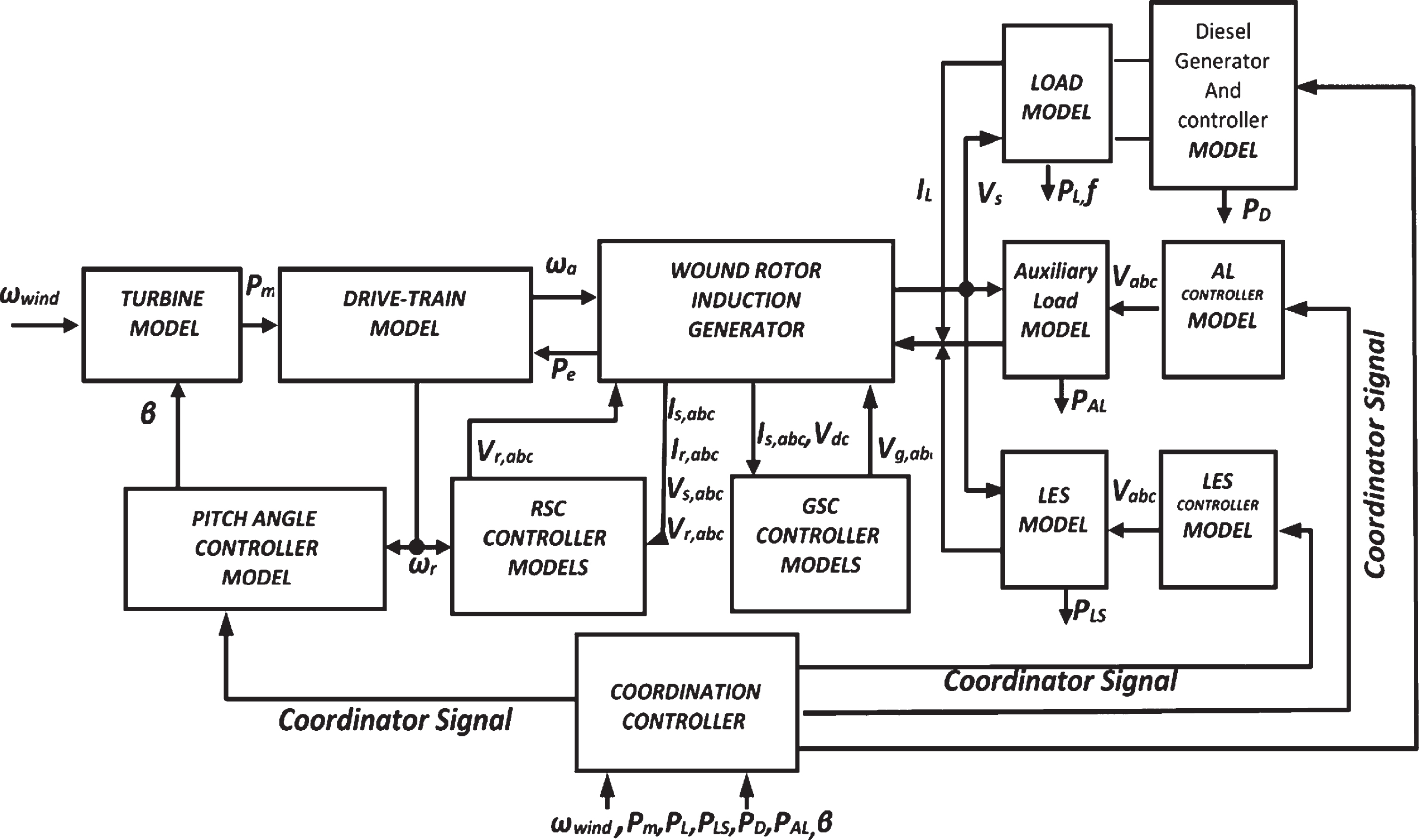
Functional block diagram of components control and the coordinator unit in an isolated WCES.
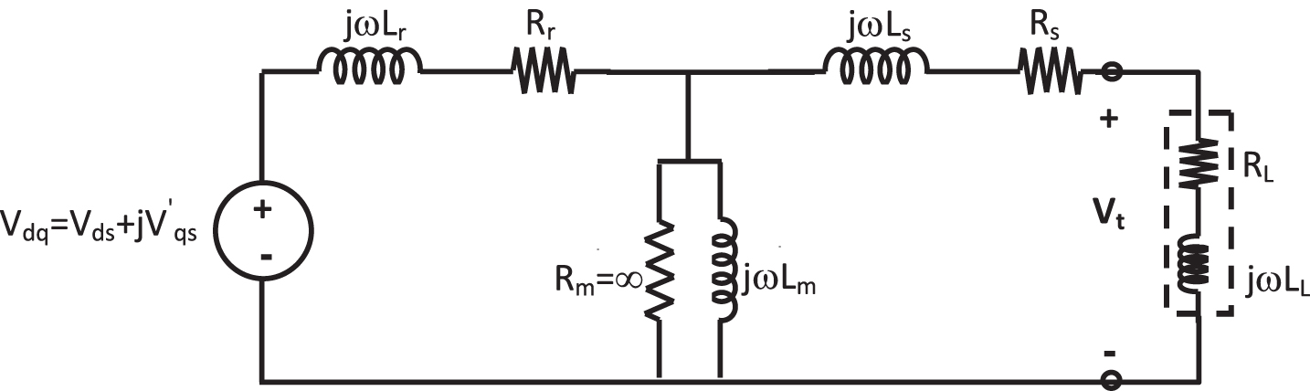
It is clear that the transient studies are carried out by considering the inherent mechanical and electromagnetic characteristics of the generator and other components of the network. The frequency-domain study is applied to determine any mode of oscillation proportional to damping factor. Hence, the frequency-domain methods are suitable for small signal stability analysis, while time-domain methods are more benefit for transient studies. Here, the time frame of interest in transient study of isolated system is limited to 0.01–3 s related to duration of transient conditions. The representation of the rotating generator and related equipment have special importance in transient studies. The classical study simplifies mathematical models of the system in order to reduce computational time of simulation related to more detailed model, whereas todays with fast and efficient simulation software this is not generally a serious concern. The model of DFIG can be implemented with different details and the selection of model is related to such constraints as simulation period, severity of transient conditions, accuracy and computational facilities. Therefore, the DFIG must be properly represented for transient conditions studies. According to Fig. 3, the most common model for DFIG includes of an internal source voltage behind a constant transient reactance [18].

Equivalent circuit of DFIG.
Several control strategies for the DFIG have been extended and studied in isolated wind energy usages from different point of view. By considering the equivalent circuit of the DFIG and the rotor and stator voltage equations in the synchronous coordinates in terms of per unit (pu), the RSC controller of the DFIG can be written as Equations (1)–(8) [32].
In Fig. 4, the control scheme of the RSC is shown. In this paper, due to significant impact of direct and quadratic currents of the rotor on active and reactive powers regulation of the DFIG and for reducing simulation time, the RSC controller is only described. Since, the effect of the ATFPI controller on transient conditions of the isolated system is studied two blocks of the ATFPI controller are placed as shown in Fig. 4. The design description of the ATFPI controller is presented in section 3.
Block diagram of the RSC controller.
For limiting the amount of the input wind energy to the WTDFIG when the rotor speed is increased more than its upper limit speed, the pitch controller increases the pitch angle. The pitch controller works according to limits of the pitch actuator, therefore it cannot vary the pitch angle very fast or over its limits. Hence, the pitch angle control is applied to prevent the absorption of excess energy of strong wind [33]. The pitch control scheme is shown in Fig. 5. According to Fig. 5, the rotor speed and its reference is compared and the error signal is multiplied by a proportional gain and then limited by a limiter block and produces the reference signal for the pitch angle. The required pitch angle is provided by comparing the active power of the WTDFIG and its reference. The coordinator signal regulates pitch angle controller action. Finally, total signals come in two limiters. The first limiter is for linearization the input signal and the second limiter limits the control signal within permitted variations region of the pitch controller.

Schematic of Pitch Angle control.
In an isolated WECS with low inertia, the fluctuating of the input power from wind to the WECS along with variations of the load may cause the system experiences instability during some transient conditions. Frequency oscillations can also be occurred according to generation and demand powers mismatch [34]. The LES system is one of the suitable and promising remedy that can be employed to cope with such problems in an isolated power network. The LES can be act as both source or sink of real power proportional to the network generation and load requirement mismatch. The LES system can effectively provide a very fast control for active power output in the isolated network and hence it is a very valuable means for frequency regulation. In transient conditions such as fault occurrence, the LES system can rapidly act and continue to control the active power. Furthermore, in presence of the LES in an isolated WECS, the oscillations in the variables can be quickly damped out and the amplitude of swings can also be forced to decrease under transient states [35].
A LES could be identified as a long duration energy storage system [36]. For current study, a bi-directional Buck-Boost DC/DC converter (see Fig. 6) is used in LES structure. Under different isolated WECS conditions, the LES operates at charging, discharging or floating modes and the modes are managed by coordinator signals. Hence, the LES is needed to provide the necessary e active power under different operating modes of the isolated network. The control schematic of the ESS is also shown in Fig. 6. The error signal is formed by the battery voltage, voltage reference and the coordinator signal. The error is passed through a PI controller and then a limiter to generate the reference current for the bidirectional converter. The capacity of the LES is determined basis on the system requirements and economic considerations. It is assumed that the LES can provide 20% of the load demand [37].
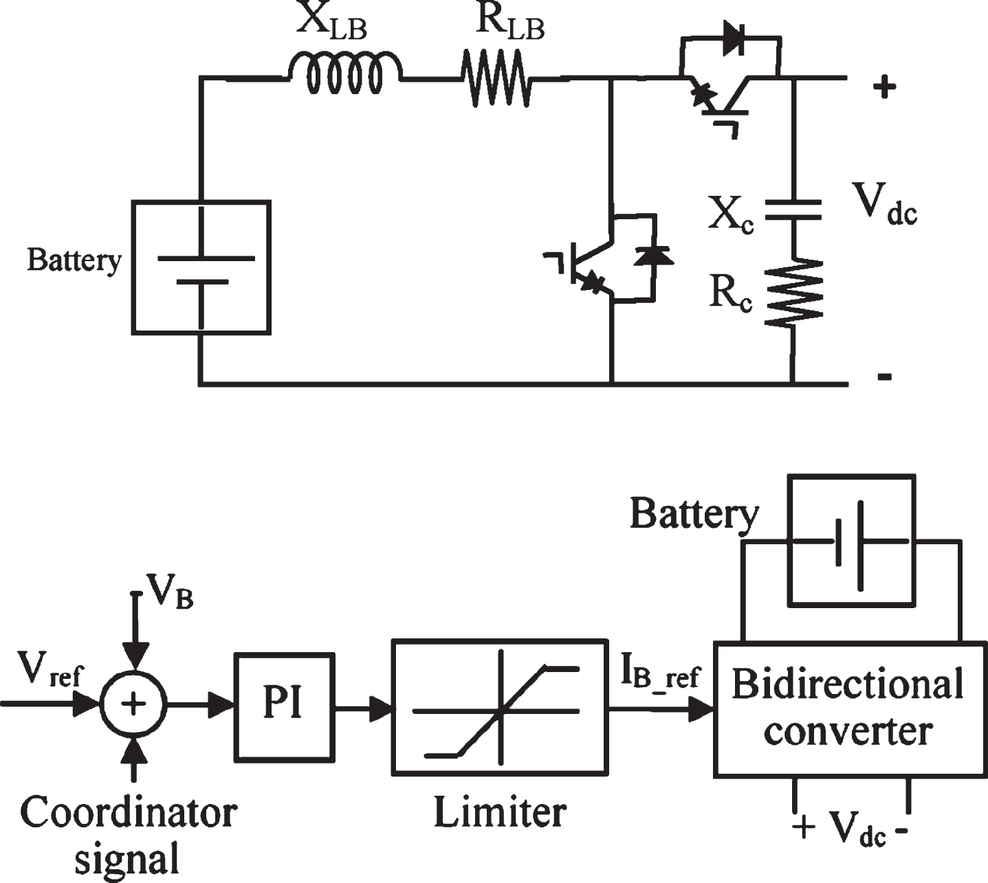
Local energy storage system and control scheme.
The auxiliary load can maintain the power balance by regulating its real power consumption between generation and consumption of active power of the network at any instant [38]. The auxiliary load of the isolated network is coordinated with the LES and the pitch control. The auxiliary load consists of two separated parts, which include a three phase converter and a three-phase resistive load. The auxiliary load starts dissipating the additional power after the LES reaches its rated capacity and pitch angle control still that the LES reaches to maximum rate. The power consumption changing of the auxiliary load will be continued till the frequency error reaches zero. The resistors operate at zero crossings of the system voltage to ensure minimum impact on the system voltage. A simplified control scheme of the auxiliary load controller is shown in Fig. 7 [14], so the coordinator unit attempts to regulate it. The auxiliary load consumption increases when the main load of the network decreases and/or the wind speed increases. The coordinator unit is deactivated when the auxiliary load increased its power consumption and the frequency has reached its nominal value.
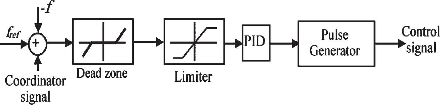
Schematic of Auxiliary Load control.
As it is shown in Fig. 7, the system frequency, the frequency reference and the coordinator signals are added up and passed through a dead-zone block. Limiter block restricts the input signal based on maximum and minimum capacity of the load. The next block is a PI controller with a set input. The analog signal of the PI controller output enters to a pulse generator.
The voltage and frequency of the isolated network are extremely important parameters that must be regulated. Here, a coordinator unit is proposed and elaborated to balance the active power between components of the system; generation and consumption and let the system to be operate in safe rages of frequency which is the most concerns of an isolated system. It becomes more important when a WTDFIG with uncertain generation operates in the system. On the other hand, the operating condition in the system can be arbitrary varied and/or a sever fault can be occurred and leads to the system experiences transient conditions that may increase the risk of instability. Hence, the second important function of the coordinator can be defined as managing such transient conditions especially in a heavy loading. So the coordinator is in fact a two-functional unit. Since, the active power (generation/consumption) of the system should be balanced, at any given moment in order to control the system frequency [38]. It is assumed that if the power flows into the system is more than the load consumption, the system frequency is increased and vice versa. If the input power of system is decreased the frequency will be reduced [33].
The control schematic of the coordinator is shown in Fig. 8 associated with the isolated system. According to the figure, the active power contribution is presented by the different components of the system to tune the frequency. Regulation of the system voltage requires maintaining the reactive power balance of the sources and sinks in the system, therefore, it is supposed that the DFIG and then the DGS are exclusively responsible for providing the reactive power necessary of the system. Therefore, the reactive power of the isolated system is not coordinated for the components of the isolated system. It is completely controlled by reactive power controller of the DFIG and the DGS according to their capacity [39].
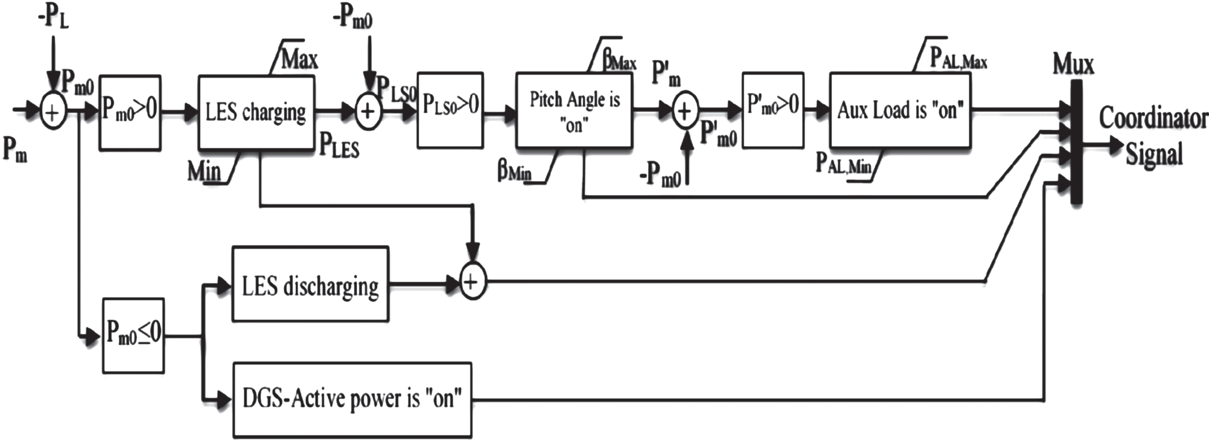
Schematic of Coordinator Unit.
According to Fig. 8, the description of the coordinator unit is as follow. Initially, the active power of the load (PL) and the active power(Pm) of the isolated system is compared, if the output power of the DFIG is more than the active power of load (i.e, Pm0 > 0) then the LES stores the additional power. Otherwise (Pm0 < 0), the LES enters into its discharge mode of operation and the DGS produced active power proportional to additional load requirement. After full charging LES, If the excessive generation of isolated system (i.e, PLS0 > 0) is more than the maximum capacity of the LES then the wind turbine pitch regulation has to be activated to control the active power flow of the system. After pitch regulation stage, if the pitch angle regulation is higher than its maximum rating and the difference of active power of system and load i.e. P’m0 > 0, then the auxiliary load has to consume the additional power associated with the isolated system. The coordination control acts in both transient conditions and steady state operation of the isolated system. The stored energy of LES is mainly charged/discharged in transient conditions because the LES acts very fast and continuous to control the active power for reply to oscillation of system quantities. The produced active power of DGS is also consumed in steady state condition of isolated system in low wind speed state.
In an isolated WTDFIG generation, the change of operating point is always along with the risk of instability in the system frequency. Therefore, transient conditions caused by changing from one operating condition to another, should be carefully monitored and managed to reduce the risk and stablish a reliable control. To do so, a control strategy based on fuzzy set theory is proposed in this section. By employing fuzzy controller, the complexity of the RSC control and the computational burden are reduced. Intelligently selecting the PI controllers in the RSC and replacing with elaborated ATFPI controllers can be certainly improved unavoidable transient conditions. This control strategy is designed to maintain the voltage and frequency in the acceptable ranges and realized by using the ATFPI controller in the RSC controller of the DFIG. For enhancement the effect of the fuzzy controller, speed up calculation time of simulations and reducing of controller errors, two CPI controllers (CPI1, CPI3) of the RSC are redesigned with the ATFPI controller (see Fig. 4). In fact, by introducing the minimum number of fuzzy PI controller instead of PI controller can successfully manage the transient conditions and this means increasing the reliability.
The output SF is tuned online by the Gain Factor (GF). The value of the GF is determined by the rule base with the error and change in error according to input parameters of the RSC controller. The proposed ATFPI controller concentrates on the tuning of the output SF due to its strong impact on the performance and stability enhancement of the system. The ATFPI controller continuously adjusts its output SF in each sampling instance by factor of k as updating gain. The value of k is determined by distinct fuzzy rules. The block diagram of the ATFPI controller is shown in Fig. 9. According to Figs. 9 and 4, yref and y are respectively the reference and measured values of the active and reactive powers of the stator of the DFIG. The ATFPI controller consists of five basic parts including: Fuzzifier, Inference Engine, Defuzzifier, scaling factor and tuning of output SF [28].
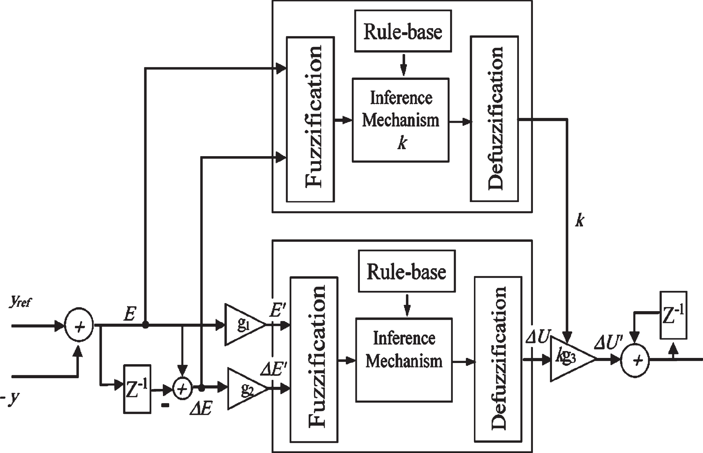
Schematic of the proposed ATFPI controller.
Seven linguistic labels (Large Positive) +L, (Medium Positive) +M, (Small Positive) +S, Zero (Z), (Large negative) -L, (Medium negative) -M, (Small negative) – S, are used by the membership function to decompose the input variables into fuzzy sets and vice versa. All MFs for controller inputs, i.e. E and ΔE, controller output, i.e. ΔU and the MFs for k are also defined on the normalized range [– 1; 1]. The symmetric Trapezoidal is used with equal base for MFs and have an overlap with neighboring MFs as shown in Fig. 10. In the ATFPI controller, the error (E) and its rate of change (ΔE) are normalized, fuzzified, and expressed as fuzzy sets.
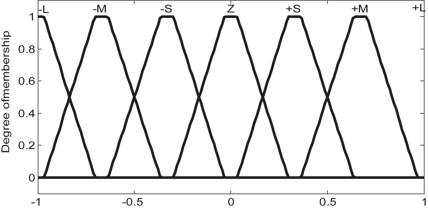
Fuzzy membership function.
The behavior of the controller is managed by a set of rules which relate the input and output variables of the controller. The rules can be designed by an expert. The rule would be:
The set of rules for the ATFPI controller is shown in Table 1. It presents a certain control doing for a given E and ΔE. Considering Table 1, each entrance in the table is a rule and hence 49 rules are generated based on the expert knowledge of the fuzzy controller. These rules are basis to decide the suitable control behavior.
Fuzzy Rules of ATFPI Controller
There are various methods for defuzzification. The Mean of Maxima and the Center of Area methods are mainly used in the defuzzifier section. The center of Area method is commonly applied in control applications. This method is used here in the ATFPI controller [40].
The SF is required to convert the normalized area to specific operating areas or vice versa. An output SF converts the normalized controller output of defuzzifier into a real control output value and act as a gain of a CPI. The SF has an important role in the stability and performance of the controller. The SF is tuned online by the GF whose value is evaluated by the error and change in error of the input controller of the RSC. The input and output SFs are not tune simultaneously because of the complexity of control, increase the time of calculations and failure to obtain the desired result. Therefore, here and in order to achieve a suitable performance, the output gain of the ATFPI controller is updated. The relationships between SFs (g1, g2 and g3) and the input and output variables of the ATFPI controller are as follows:
Similar to conventional PI, the initial values of these parameters are determined by Ziegler-Nichols method and then modified based on trial and error procedure and expert knowledge. The values of g1, g2 and g3 are given in Appendix. The gain of k is computed online by using a separate fuzzy rule-base defined on E and ΔE. The fuzzy rules used for calculating k are as:
In the presented scheme for tuning of the ATFPI controller, the output SF of the ATFPI controller is modified with gain factor k based on error and change in error in dependence on the performance of the closed loop control system. Hence it can be said that the ATFPI controller is similar to a common FPI with a dynamic gain. The gain of k is obtained according to its rule-base (see Fig. 9). Therefore, the output gain of the ATFPI controller is variable proportional to gain of k and it is modified online while the controller is in work and input parameters of the controller is variable depending on the behavior of the system in each time instant. The main reason for online gain variation of the output SF of the ATFPI controller is to create controller response based on specifications of desired behavior of the system. For evaluation of the system performance equipped with the ATFPI controllers, three states are introduced for replacement of the conventional PI controllers (CPI1 and CPI3) with ATFPI controllers. The arrangements may be categorized as: 1) CPI1 is Fuzzy, 2) CPI3 is Fuzzy, 3) CPI1 and CPI3 are Fuzzy.
The Isolated Study System (ISS) is shown in Fig. 11. The main components of the ISS includes: wind turbine unit, local energy storage system, local load, auxiliary load and the DGS. The characteristic of system components is provided in Appendix.

Single line diagram of the Isolated Study System.
As it is shown in Fig. 11, the desired voltage magnitude of the rotor is supplied by using the LES system at the RSC of the DFIG. The stator voltage magnitude and frequency are adjusted by the rotor voltage magnitude. Three distinct operating conditions may be happened in the ISS; 1) the produced wind power is more than the requirement power of the load, 2) the produced wind power of WTDFIG is less than the load requirement, 3) wind speed is less than the cut-in speed of the WTDFIG. The performance of the proposed controller in the ISS is assessed under these triple situations in Matlab/Simulink environment. In this section, the performance of the ISS is investigated under different transient conditions and various arrangements of ATFPI controllers in the RSC. Simulation results for these arrangements are compared with those obtained with CPI controllers. The interval for studying transient conditions is assumed to be 15 ms, longer interval imposes a huge computational burden and it may increase the risk of losing fast swings in obtaining the results. On the other hand, the ISS may be faced to some various events or contingencies which inherently causes transient conditions; i) startup of the ISS, ii) disconnection of the WTDFIG, iii) disconnection of the LES, iv) disconnection of the local load, and finally v) phase to ground fault. Four criterion include Percent of OverShoot (POS), Rise Time (RT), Settling Time (ST), Steady State Error (SSE) are employed to evaluate the proposed controller performances. Moreover, four control measures: Integral Squared Error (ISE), Integral Absolute Error (IAE), Integral Time-weighted Squared Error (ITSE), Integral Time-weighted Absolute Error (ITAE), are chosen to compare the output results of various transient conditions. The Reactive power and frequency at load bus B1 are considered as output results of the simulations under various conditions.
Figure 12 shows the startup performance of the ISS for various arrangements of the ATFPI controller in comparison with the CPI controller. The quantities of POS, RT, ST and SSE of the reactive power and frequency of the ISS with ATFPI1, ATFPI3, ATFPI1 & ATFPI3 and CPI controllers are presented in Table 2. Since the LES is also connected to the ISS and the startup performance of LES is faster than the WTDFIG therefore its output frequency is assumed to be 60 Hz. Hence, the startup frequency of the ISS is almost begun at 60 Hz. In the startup condition when the ATFPI controller is employed, the active power of the load and the system frequency have low fluctuations. In addition, at the startup manner the active power of the DFIG is proportional to the internal voltage of the DFIG.

Frequency, active power, reactive power and voltage of the load under startup condition.
Comparison performance of ATFPI and CPI controller arrangements
This voltage is produced with direct and quadratic currents of the RSC. So, online tuning of coefficients of the ATFPI controllers can improve the system performance compared to the CPI controller with constant gains. According to the Fig. 12 and Table 2, the performance of the ISS with ATFPI1 & ATFPI3 controllers has short ST respect to CPI controller. For all arrangements of FPI controller, the ISS has smooth oscillations. Also, according to Table 3 (the results are normalized), the amount of the ISE, IAE, ITSE and ITAE control measures in the case of ATFPI control are far less than CPI controller and the fuzzy controller is more successful in minimizing the control measures.
ISE, IAE, ITSE, ITAE criterion in startup condition
Comparison performance of ATFPI and CPI controller arrangements
After the ISS reached to the steady-state condition at t = 1.0 s, the WTDFIG is disconnected from the ISS and after 100 ms the WTDFIG is connected again. This condition shows the robustness of the proposed control strategy based on the fuzzy control in confronting with a sudden disconnection. In Fig. 13 the voltage, active and reactive powers of the main load and the frequency of the system are illustrated for disconnection of the WTDFIG. Under transient conditions the generated power is reduced following disconnection of the WTDFIG and only a part of the load can be supplied by the LES.

Frequency, active power, reactive power and voltage of the load under WTDFIG disconnection.
The DGS is not also able to supply the active power requirements in a period of 100 ms due to its high inertia. The ISS by using the ATFPI controller in the RSC remains stable after reconnecting the WTDFIG due to online change in the output gain of the ATFPI controller. These figures are presented for ATFPI1, ATFPI3, ATFPI1&ATFPI3 controllers and compared with results obtained for the CPI controller. According to the results, the performance of the ISS is unstable when the CPI controller is used. The ISS is stable in other arrangements with the fuzzy controller. The ATFPI controller by online changing of control parameters has better affect in the pass of transient conditions.
By using ATFPI3 controller and based on POS, ST and SSE control criterion, the behavior of the ISS after connection of WTDFIG is better than the performance of other fuzzy controller arrangements. By considering Table 5 (the results are normalized), the control measures of ISE, IAE, ITSE, ITAE are all decreased when the ATFPI control is in operation.
ISE, IAE, ITSE, ITAE of control measures in WTDFIG disconnection condition
At 1.0 s, the LES is disconnected from the ISS for 100 ms. Figure 14 shows the performance results of the ISS for various arrangements of the ATFPI controllers in comparison with the CPI controller. The ISS is stable only by using the ATFPI controllers. Some of the active power of the ISS is provided/consumed by the LES according to the operation mode. During LES disconnection, it acts as a consumer then the active power of the load and frequency of the ISS is increased because control is the perfect setting control parameters to reduce the error. The ISS has maintained its stability by the ATFPI controller RSC after volatility. By using ATFPI1& ATFPI3controllers, the performance of the ISS is better than other arrangement of the fuzzy controllers. After LES is disconnected from ISS due to supply part of reactive power of ISS by DGS, the voltage and reactive power consumption of load is increased. According to Table 6, the Control measures based on error is dropped significantly in ATFPI controller applying and performance of system is improved.

Frequency, voltage, active and reactive powers of the load under LES Disconnection.
ISE, IAE, ITSE, ITAE of control measures in LES disconnection condition
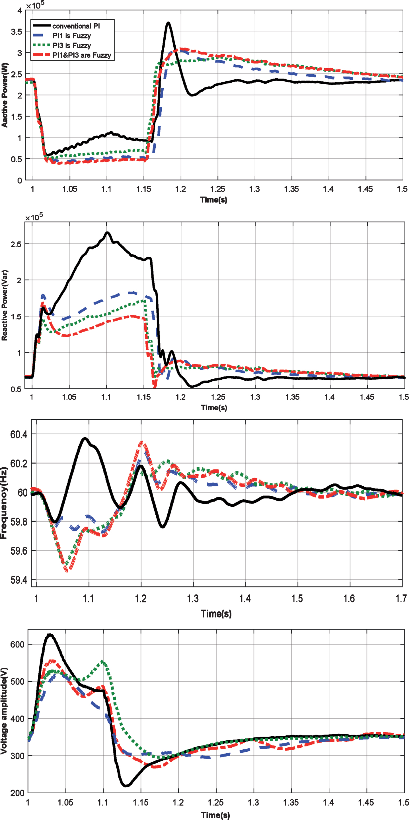
The responses of the system following a change in the load are shown in Fig. 15. Initially, the system is loaded with its rate. At t = 1.0 s, the load is disconnected and it is returned after 100 ms. By referring to the results shown by Table 7, FPI controllers can satisfactorily reduce POS, RT and SSE criterion. Under such situation, the total active power demand is considerably reduced to the auxiliary load and LES charging capacity demands. The coordinator unit sends control signals to the pitch angle controller, the auxiliary load and the LES. After load disconnection, the system frequency is increased significantly. Figure 15 clearly shows that the performances of the ATFPI is much more successful than the CPI. Online adjusting the control parameters of the ATFPI alleviates the amplitude of oscillations and reduces the time for reaching to the stability. Moreover, the amounts of ISE, IAE, ITSE, ITAE indices given in Table 8, may confirm that optimistic improvements in the system performances has been attained.

Frequency, active power, reactive power and voltage of the load under load disconnection.
Comparison performance of ATFPI and CPI controller arrangements
Comparison performance of ATFPI and CPI controller
In this case, according to Fig. 11 at t = 1.0 s a phase of PCC bus (B1) is shorted to the ground through a very low impedance and takes 150 ms. Figure 16 shows the responses of the ISS under such condition. Since the fault impedance is low the active power received by the load is significantly dropped. The behavior of the ISS also depends on the control of the RSC during the fault. According to Table 9, The POS in the reactive power with CPI controller is almost two times larger compared to the ATFPI controller.
Frequency, voltage, active and reactive powers of the load under phase to ground fault.
Comparison performance of ATFPI and CPI controller arrangements
As well as, by using the CPI controller the settling time of the output parameters of ISS are about four times larger than the output performances of the ISS by using the ATFPI controllers. By using ATFPI controllers, the amplitude of the oscillations in the voltage, active and reactive powers and frequency are smaller than the CPI controller under fault condition. By referring to Table 10, the ISE index is minimum when the ATFPI1 and ATFPI3 are applied as DFIG controllers. Minimizing ISE criteria means that the controller pushes to large errors which normally take place in the early times of each transient condition to be decreased as quickly as possible. This in turns leads to fast responses of the ISS with considerable low amplitude oscillation.
Comparison performance of ATFPI and CPI controller
In this paper, an efficient control strategy based on the ATFPI is introduced and applied to the RSC controller of the DFIG in an isolated WECS. The output gain of the ATFPI controller is tuned online under transient conditions. Two ATFPI controllers are applied to the RSC controller and a coordinator unit is designed to regulate the voltage and frequency of the ISS in various transient conditions. The performance of the ISS by using the ATFPI controller is compared with the CPI controller in various conditions. Simulation results show that the performance of the ISS by using the proposed control scheme is much better than the CPI controller. Under the WTDFIG and LES disconnection states, The ISS is unstable by using the CPI controller. Moreover, by using the ATFPI controllers, the control measures of the reactive power and frequency of the ISS is significantly reduced in comparison with the CPI controller and this leads to fast responses with considerably low amplitude in oscillations.
Footnotes
Appendix
|
|
|
| Damping factor axis(D) = 1.5 | Turbine inertia constant(Ht) = 3s |
| Nominal mechanical output power (W):3e6 | Generator inertia constant(Hg) = 0.5s |
|
|
|
| Rotor inductance(Lr) = 0.156p.u | Rotor resistance(Rr) = 0.005p.u |
| Inductance(Lm) = 2.9p.u | Stator resistance(Rs) = 0.0076p.u |
| Stator inductance(Ls) = 0.171p.u | |
|
|
|
| Kp1 = 1,Ki1 = 100, Kp2 = 0.3,Ki2 = 8, Kp3 = 1.25,Ki3 = 300, Kp4 = 0.3,Ki4 = 8,Kp5 = 0.002,Ki5 = 0.05, | |
| Kp6 = 1,Ki6 = 100, Kp7 = 1,Ki7 = 100,, PS* = Qs*=1p.u | |
|
|
|
| g1 = 0.152, g2 = 0.0012, g3 = 0.135 | |
|
|
|
| ωref=10deg/s,KP = 150, PWTref = 3MW | |
|
|
|
| P = 0.240MW | Q = 0.75MVar |
| Voltage = 380V | |
|
|
|
| Power factor(pf) = 0.8 | Real power = 1MW |
|
|
|
| f ref = 60 Hz,KP = 0.86,KI = 0.35,KD = 1.42 | |
|
|
|
| Nominal Voltage = 1200V | Rated Capacity = 10Ah |
| XLB = 0.2199p.u,RLB = 0.2p.u,XC = 0.356p.u,RC = 0.18p.u | |
|
|
|
| KP = 0.85,KI = 2.5, KD = 1.2,Vref = 1200V | |
|
|
|
| Stator resistance(Rs) = 0.0176p.u | Reactances [Xd Xd’ Xd” Xq Xq” Xl] (pu) = |
| [3.23, 0.21, 0.15, 2.79, 0.37, 0.09] | |
| Time constants [Tdo’ Tdo” Tqo”] (s) = | |
| [ 1.7 0.008 0.004] | |
|
|
|
| Regulator gain and time constant [Ka Ta(s)] = [300, 0.001] | |
| Exciter [Ke Te(s)] = [1, 0] | |
| Transient gain reduction [Tb(s) Tc(s)] = [0, 0] | |
| Regulator output limits and gain [Efmin, Efmax (pu), Kp] = [– 11.5, 11.5, 0] | |
|
|
|
| Length = 10Km | Resistances (Ohms/km) = 0.1153 |
| inductances (H/km) = 1.05*10-3 | |
|
|
|
| Voltage = 380 V(L-L) | Frequency = 60Hz |
| Fault impedance = 2e-9Ω | |