
Abstract
Doubly-fed induction generator (DFIG) is the most commonly used technology for wind power generation due to the variable speed performance, decoupled control of active and reactive powers, and high efficiency. However, the DFIG originally cannot participate in damping of power system oscillations since it is not synchronously connected to the power system. This paper proposes an optimal and robust additional damping controller for the DFIG wind turbine to contribute it to damp power system oscillations. It is a fuzzy logic controller that its parameters are optimally tuned using the genetic algorithm (GA). The proposed controller modifies the DFIG active power output by using feedback from grid oscillations. Here, a comparative study is carried out for different feedback signals to determine the best of them. Comparing the results reveal that the rotor speed difference of synchronous generators is the best feedback signal to damp power system oscillations. Time domain simulations also confirm the effectiveness and robustness of the proposed controller under both the small and large disturbances.
Nomenclature
DFIG Wind Turbine
Wind density
Wind turbine’s blade length
Wind velocity
Wind turbine power coefficient
Turbine and generator inertia
Mechanical and electrical torques
Turbine and generator angular speed
Damping and stiffness of shaft
Shaft twist angle
d and q axis stator currents
d and q axis rotor voltages
Electrical base and synchronous speed
Stator and rotor resistances
Stator, rotor and mutual inductances
Stator transient inductance
Rotor time constant
d and q axis voltages behind transient reactance
Syncharonous Generator
Mechanical and electrical powers
rotor angular speed and position
rated angular speed of power system
Inertia and damping coefficients
Introduction
During the last decades, the increase in environmental pollution and the decrease in fossil fuel reserves have attracted more attention to generating electric power using renewable and clean energies. Among the various resources, wind energy has the fastest growth due to the widespread availability and economic and technical reasons. Initially, wind power was generated using the squirrel cage induction generator (SCIG). Today, however, DFIG is the most commonly used technology. It is a wound rotor induction generator that is joined to the network with stator directly and rotor through back-to-back power electronic converters. In this case, the wind turbine provides variable speed performance for extracting optimal power from the wind, flexibility in control of active and reactive powers, and higher efficiency [1, 2]. However, the DFIG originally cannot participate in damping of power system oscillations since it is not synchronously coupled to the power system. Therefore, with increasing the penetration level of DFIG-based wind farms in power systems, the concerns related to the system stability and oscillations damping will find the highest degree of importance.
To solve this problem, some papers have suggested the use of a supplementary damping controller for DFIG wind turbines. This controller modifies the DFIG power output based on feedback from power system oscillations. For example, the study [3] was proposed a proportional integral (PI)-based damping controller for DFIG to improve power system oscillations based on the wind turbine’s rotor speed oscillations. In [4], the conventional power system stabilizer (PSS) with a lead-lag controller has been suggested for DFIG wind turbines whereas the feedback signal is the DFIG active power oscillations. Also, in [5], a fuzzy damping controller has been proposed for DFIG wind turbines using the rotor speed and acceleration as the feedback signals. However, such signals are less sensitive to the system oscillation modes since the DFIG wind turbine is decoupled from the power system via power electronic converters [6]. On the other hand, such signals are affected by torque variations concerning the tower shadow [7]. A PI-based damping controller was designed in ref [8] by using feedback from grid frequency oscillations. Also, a local measurement of power system oscillations has been proposed by the angular speed oscillations and the voltage angle of DFIG terminal in [9] and [10], respectively. A PSS has been suggested for DFIG wind turbine in [11] to damp power oscillations by using feedback from active power of tie-lines. Also, in [12, 13], the angular speed difference of synchronous generators with higher participation factors in the system oscillation modes have been used by a classic lead-lag controller as the feedback signal of the proposed damping controller.
As reviewed above, different feedback signals have been employed by the damping controllers in DFIG wind turbines. However, there is no explanation about the reason or mechanism of selecting the feedback signals. In this paper, a comparative study is carried out to select the best feedback signal for the damping controller of DFIG wind turbines. To do so, an optimal and robust damping controller is designed using the fuzzy logic approach. The main advantage of fuzzy controllers is that they do not require detailed mathematical modeling of the system. The fuzzy method can also overcome the nonlinearities and uncertainties of the system and provide robust performance over a wide range of operating conditions and transient events [14, 15]. Moreover, in this paper, for the sake of easy design and implementation, the normalized fuzzy membership functions are used while the inputs and output of the fuzzy controller are scaled by suitable coefficients. The scaling factors and membership function parameters will be optimally determined using the genetic algorithm. Also, the proposed fuzzy controller is separately designed by taking into account different feedback signals, and the results are compared to find the best of them.
The rest of the paper is sectioned as follows: a brief description of the model of DFIG-based wind farm and conventional synchronous generators can be found in Section 2. The proposed fuzzy controller is designed in Section 3. The results of the study are presented and discussed in Section 4. Finally, the main findings are summarized in Section 5.
Modeling the DFIG-based wind farm
A wind farm practically includes a large number of wind turbines. However, considering each wind turbine in the modeling process raises the complexity and simulation time of the system. To solve this problem, an aggregation method can be used which models a wind farm as a single equivalent wind turbine [16]. Therefore, the DFIG-based wind farm is considered as an aggregated wind turbine model in this paper, as shown in Fig. 1.

Schematic diagram of the DFIG wind turbine.
The wind turbine gets the kinetic energy of wind and delivers it in the form of rotating mechanical torque. It can be calculated by [16]
The mechanical torque extracted by the wind turbine is transmitted to the generator’s rotor through a drive-train system. The drive-train dynamics are usually described by a two-mass model as follows [16]
In DFIGs, the generator is a wound rotor induction generator that both stator and rotor windings are connected to the network. For power system stability studies, very fast electric transients of the stator are usually neglected, and the system is modeled in the form of a voltage source behind a transient reactance. In this condition, the rotor electrical dynamics within the d-q reference frame are described as follows [16]
As shown in Fig. 1, the rotor winding is connected to the power system through two back-to-back power electronic converters. The converters should be able to work in both rectifier and inverter modes to provide a bidirectional path of the power flow. They are usually modeled in the form of PWM voltage source converters for injecting a controlled sinusoidal AC three-phase voltage to the rotor winding [17]. In this case, the rotor voltages are adjusted by the rotor-side converter (RSC) to extract optimal power from the wind and decoupled control of active and reactive powers of the generator. To achieve this aim, the RSC can be controlled through decoupled d-q vector control of rotor currents. On the other hand, the major role of the grid-side converter (GSC) is to maintain constant dc-link voltage and regulate the reactive power exchange between the GSC and the grid [17, 18].
Mathematical description of system oscillation characteristics
In this section, the dynamic equations of a typical regional power network are developed to analyze the system oscillation characteristics. For example, Fig. 3 demonstrates the single-line diagram of two-area power system, where G1 and G2 care the equivalent generators in the feeding-side and receiving-side, respectively. The swing equations of each generator are given by [20]
In Equation (7), the electric output power of G1 and G2 can be calculated as [20]
By considering the mechanical power is constant and replacing Equation (8) into Equation (7), the state equations of the system for a small perturbation around operating point are obtained as follows [21]
Where
Based on Equations (9)–(11), the system dynamics depend on the system parameters. To evaluate the impacts of these parameters on the stability of system oscillations, a reduced-order model based on the integral manifold theory can be used to integrate and eliminate unneeded differential equations. Accordingly, the system reduced-order model is derived as follows [22]
From Equation (13), the system characteristic equation is obtained as
Subsequently, the system eigenvalues are given by
In general, the real parts of the eigenvalues play major role in damping of system oscillations, such that if they become more negative, the damping will be increased. According to Equation (16), in a regional power network, the eigenvalues’ real part (α) is directly related to the inertia gain of the receiving-side (H2). Consequently, it can be concluded that supporting more inertia from the wind farms in the receiving-side through using an additional damping controller in the DFIG’s active power control loop may increase the power system oscillations damping.
Generally, the power system oscillations can be specified by the angular speed deviations between the synchronous machines or the areas. For example, for a two-machine system (or two-area system) shown in Fig. 2, the oscillations can be considered as Δω12 = Δω1 - Δω2. This is a global signal that can be obtained using the wide-area measurements. In the oscillatory conditions, one period of Δω12 can be divided into four stages, as represented in Fig. 3. In stages I and III, the amplitude of Δω12 is increasing and a larger damping signal can restrict it. In return, in stages II and IV, its amplitude is declining and a lower signal will accelerate the oscillation damping. Thus, an adaptive damping controller can help to damp the system oscillations. In a practical manner, the stages I to IV can be recognized through deviations of Δω12 and its change rate (d (Δω12/dt), as presented in Table 1. Accordingly, if both the Δω12 and its change rate are negative, then the oscillation is in stage I. On the other hand, if Δω12 is negative and d (Δω12/dt is positive, the oscillation will be in stage II. Subsequently, in stage III, both the value of Δω12 and d (Δω12)/dt are positive. Finally, if Δω12 is positive and d (Δω12)/dt is negative, the oscillation will be in stage IV.

Single line diagram of two-area network.
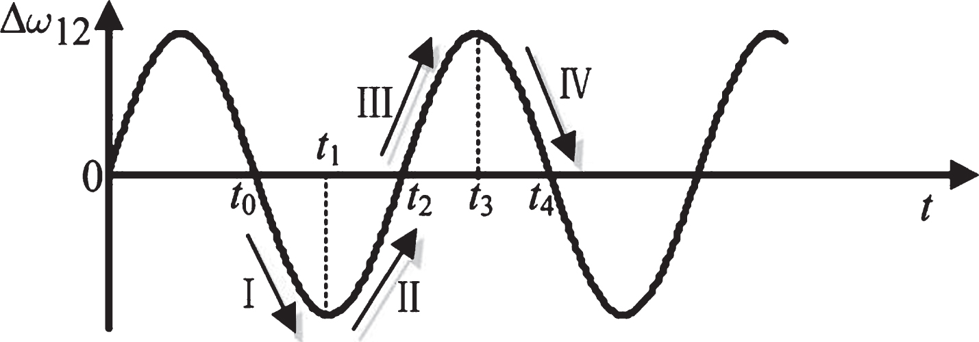
Oscillation stages.
The fuzzy decision table
General structure
Traditionally, the DFIG’s active power output is determined using the maximum power point tracking (MPPT) strategy [16]. However, the DFIG wind turbines with MPPT control strategy provide no inertial response since the active power control is decoupled from power system dynamics. On the other hand, as discussed in the previous section, supporting inertia response from the wind farms may increase the power system oscillations damping.
This paper proposes an additional damping controller in the active power control loop of the DFIG’s rotor-side converter to improve power system oscillations. Fig. 4 represents the general structure of the RSC controller together with the proposed damping controller. As shown in the figure, the damping controller modifies the reference of DFIG active power by using feedback from power system oscillations. In the next subsections, the proposed damping controller will be designed.

The structure of RSC controller together with the proposed damping controller.
In this section, the proposed damping controller is designed using the fuzzy logic approach. The fuzzy controller usually receives two inputs as the error (e) and the change rate of error (Δe) of a control feedback signal [15], as shown in Fig. 5. In the first step, these crisp input signals will be converted into the corresponding fuzzy values. In this paper, for the sake of easy design and implementation of the fuzzy membership functions (MFs), the input signals are firstly scaled at the range of [-1, 1] by two gainsK1 andK2. Afterward, the normalized MFs determine the membership degree of the input variables to one of the fuzzy sets. Fig. 6 depicts the normalized triangular MFs used in this paper as the fuzzifiers for both the input signals.

Structure of the fuzzy controller.
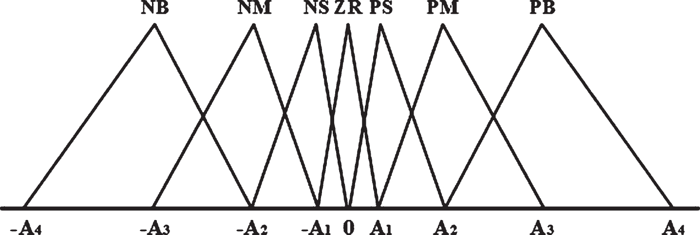
The inputs and output MFs.
In the next step, the fuzzy inference system deduces the appropriate fuzzy control based on the available fuzzy rules and fuzzy inference engine. The implication of fuzzy rules requires a sufficient knowledge and experience about the practical system. They are expressed by a set of linguistic statements linking a limited number of conditions with a limited number of consequences, in the following form:
Based on the discussion in subsection 3.2, two fuzzy values (negative and positive) for each of the input variables (e and Δe) can determine the appropriate control action. However, for those applications that need high control accuracy, the input and output should be divided into more small segments, and more fuzzy rules should be applied. Accordingly, seven fuzzy values are taken into account for each of the input and output variables, as: NB = negative big, NM = negative medium, NS = negative small, ZR = zero, PB = positive big, PM = positive medium, PS = positive small.
Table 1 gives all the fuzzy control rules applied in our proposed damping controller. The rows and columns represent two inputs (e and Δe), and those inputs are related to IF parts in IF-THEN rules. The conclusion or control output can be considered as a third dimensional variable that is located at the cross point of each column and each row, and that conclusion is associated with the THEN part in IF-THEN rules. For example, when the angular speed deviation between the areas 1 and 2 (Δω12) is NB, and the change rate of Δω12 is also NB, the DFIG’s active power damping signal (P d ) should be NB to damp the inter-area oscillations as soon as possible. All other rules can follow a similar strategy. These rules anticipate that the desired operating point will be reached soon and stabilization control is no longer needed.
As indicated, seven fuzzy values are considered for each of the input variables, given in the top row and the leftist column of the table. Accordingly, 49(= 7 ×7) fuzzy rules determine all the possible relationships between the input and output variables, given in the body of the table. Each of the 49 control rules represents a desired controller response to a particular situation. The control rules were designed to be symmetric under the assumption that if necessary any asymmetries could be best handled through scaling. In addition, adjacent regions in the rule table allow only nearest neighbor changes in the control output (NB to NM, NM to NS and so on). This ensures that small changes in e and Δe result in small changes in (P d ).
In this paper, the fuzzy inference system employs the Mamdani-type structure and the Max-Min method [14]. Also, the triangular MFs and the centroid of area (COA) method [15] are used for defuzzification of the output control variable. Defuzzification is the final step in designing the fuzzy controller. It is the procedure of converting the fuzzy output value into the corresponding crisp value. In this study, the output values are scaled in the range of [–0.15 + 0.15] according to the control limits. The gain K3 is considered to scale the output value in a proper output range.
Traditionally, the fuzzy controllers are tuned using trial and error. However, it is a very time consuming task and may reach the local optimum. In this paper, the genetic algorithm is used to guaranty the optimal performance of the proposed fuzzy controller. This method is a powerful tool to obtain the global optimal solutions for any optimization problem [20, 21]. Here, we intend to optimize the fuzzy controller performance for obtaining the best damping controller. Therefore, the optimization problem will be converted into determining the optimal solution of a damping objective function. In this case, the integral of absolute error (IAE) of the relative rotor angles of synchronous generators can be considered as the optimization performance index, as following form [22]
Figure 7 represents the flowchart of the GA optimization process. The optimization is started by initializing the system parameters and randomly generating an initial population. The initial population includes 20 chromosomes each consisting of 7 gens. The first four genes are associated to the MFs parameters, i.e., A1, A2, A3 and A4 in Fig. 6, and the rest three genes are the scaling factors K1, K2 and K3. Subsequently, the selection, crossover and mutation operations take place to reproduce the next generation. Through selection, the chromosomes with high fitness are replicated in the next generation while those with low fitness will be fewer or not at all. Crossover is to take more than one parent solution and produce a child from them. In this operation, a chromosome is divided into two parts and recombined with another chromosome with the same crossover point. Mutation randomly changes a gene of a chromosome to maintain the genetic diversity from one generation to the next. Finally, the old generation is replaced with the new one. This procedure is repeated until the termination condition is fulfilled. At the end, the chromosome with minimum performance index will be selected as the best solution.

The GA Flowchart.
Test system and modal analysis
In this paper, the system shown in Fig. 8 is considered as the test system. It is a standard two-area four-machine power system developed in [19] that one of its synchronous generators has been replaced with a DFIG-based wind farm. The area 1 contains two conventional synchronous generators (G1andG2), one aggregated load (L1). The area 2 also includes on conventional synchronous generators (G3) , one aggregated wind farm (DFIG), and one aggregated load (L2) .The power flow of the generation units and the loads can be seen in Fig. 8. Also, as marked in the figure, the area 1 nominally sends about 400 MW to the area 2 via the power tie-lines. The wind farm has been modeled as a single equivalent wind turbine with capacity of 700MW and unity power factor. It is worth noting that although the wind farm practically includes a large number of wind turbines, however, considering each individual wind turbine in the modeling process raises the complexity and simulation time. To overcome this problem, the aggregation method is used in this paper [16].

Single-line diagram of the test system.
The test system was simulated in MATLAB/Simulink software, and its linear state-space model was extracted by using the linmod command. The complex eigenvalues of the state matrix along with the frequency of oscillations, the damping ratio, and the normalized participation factor (NPF) of dominant states in each mode [23] are given in Table 2. Mode 1 is associated with the DFIG rotor electrical dynamics. Mode 2 is the shaft torsional mode of DFIG. Modes 3 and 4 are associated with the excitation of synchronous generators. Mode 5 is the local oscillation mode of area 1. Finally, mode 6 is an inter-area oscillation mode.
Modal analysis of the test system
As stated earlier, a variety of feedback signals are employed in this study, as the input of the proposed GA-based fuzzy damping controller (GAFDC) to select the best of them. They are both the local and remote signals as follows:
w v (θ v ): A local feedback of power system oscillations is the angular speed deviation (or the phase angle changing rate) of the wind farm’s bus voltage. In this case, a phase lock loop (PLL) can be used to measure the angle between the synchronously rotating d-q frame and the phasor voltage of DFIG bus, as modeled in [24].
w d : This is the angular speed deviations between the synchronous generators which have higher participation factors in the power system oscillation modes. According to the results of the modal analysis given in Table 2, the generators SG1 and SG3 have higher participation factors in the test system oscillation modes. Therefore, ω d = (Δω1 - Δω3) can be considered as a feedback control signal. It requires remote measurements.
p its : This is the active power oscillations between the areas. Since the system oscillations are directly related to the active power oscillations, this signal can be an effective method for damping of the oscillations. It is a remote signal.
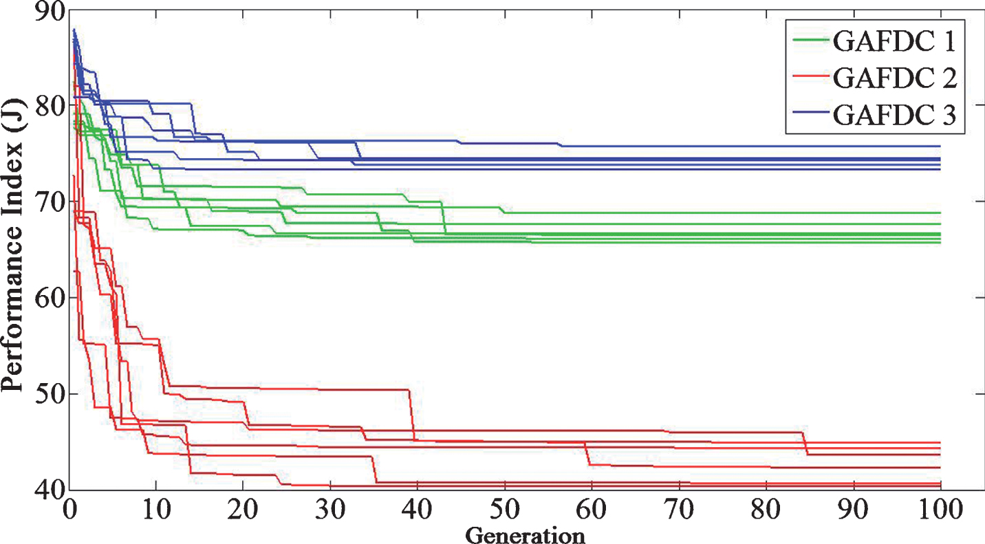
To select the best feedback signal, the proposed GAFDC is separately designed by taking into account different feedback signals. Fig. 9 compares the convergence trends of the GA performance index (J) for 100 generations where GAFDC1, GAFDC2 and GAFDC3 respectively refer to the proposed controller with feedback of θ v , ω d , and P tie . As can be seen in Fig. 9, the GA was run for various simulations in each case. Table 3 gives the average results of the best solutions and the final convergences (J avg ). From the obtained results, the minimum value of J avg is achieved by the GAFDC2. It means that ω d provides the best performance as the feedback signal for the proposed damping controller. On the other hand, the maximum value of J avg is achieved when P tie is considered as the feedback signal. To confirm the obtained results, time domain simulations will be also conducted in the next section.
Comparing the GA performance index evolutions.
The average GA solutions
In this section, the results of time domain simulations will be present as comparative analyses between the three kinds of GAFDC1, GAFDC2 and GAFDC3. These simulations were performed under both the small and large disturbances.
Case 1 (small disturbance)
In the first case, the dynamic performance of the test system under a small perturbation of wind speed is evaluated. For example, it is assumed that the wind turbine which works in the steady state with a wind speed of 13 m/s, encounters a decrease of about 2 m/s. In this condition, the operating points of the wind turbine and synchronous generators will be changed.
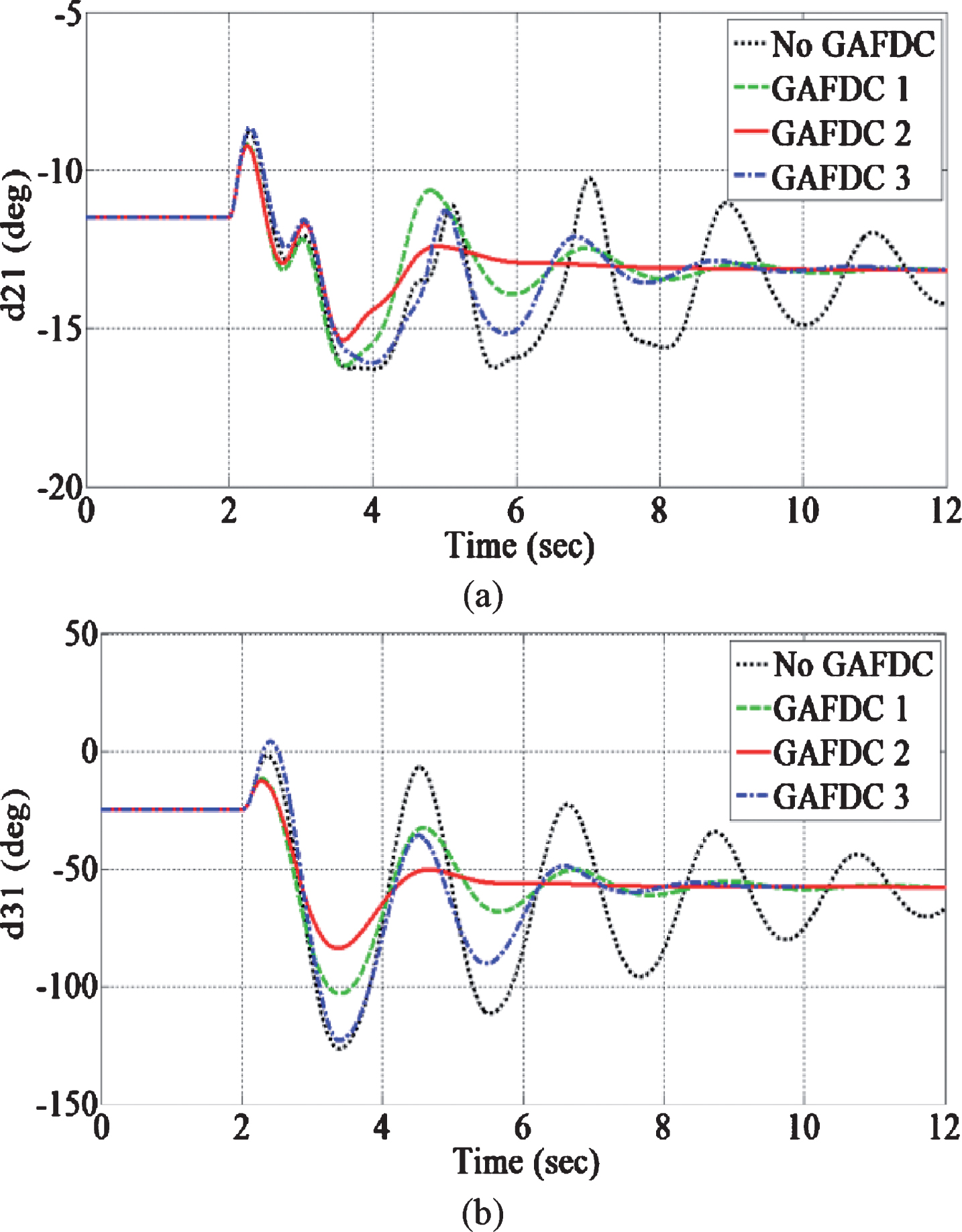
Figures 10–12 compare the simulation results of the system for without and with the three kinds of the damping controller. Figure 10(a)–(d) show the active power oscillations of SG1, SG2, SG3, and DFIG, respectively. On the other hand, Fig. 11(a) and (b) show the angular oscillations of the synchronous generators where δ21 and δ31 refer to the relative rotor angles of SG2 and SG3concerning SG1, respectively. In addition, the inter-area active power oscillations are compared in Fig. 11 (c). Based on the results, it can be seen all the three kinds of the damping controller can improve the power system oscillations compared to the base operation (No GAFDC). However, the GAFDC2 has a greater effect on reducing both the maximum deviation and the settling time of oscillations compared to the GAFDC1 and the GAFDC3. This is due to the provided damping signal by DFIG wind farm, as compared in Fig. 12.
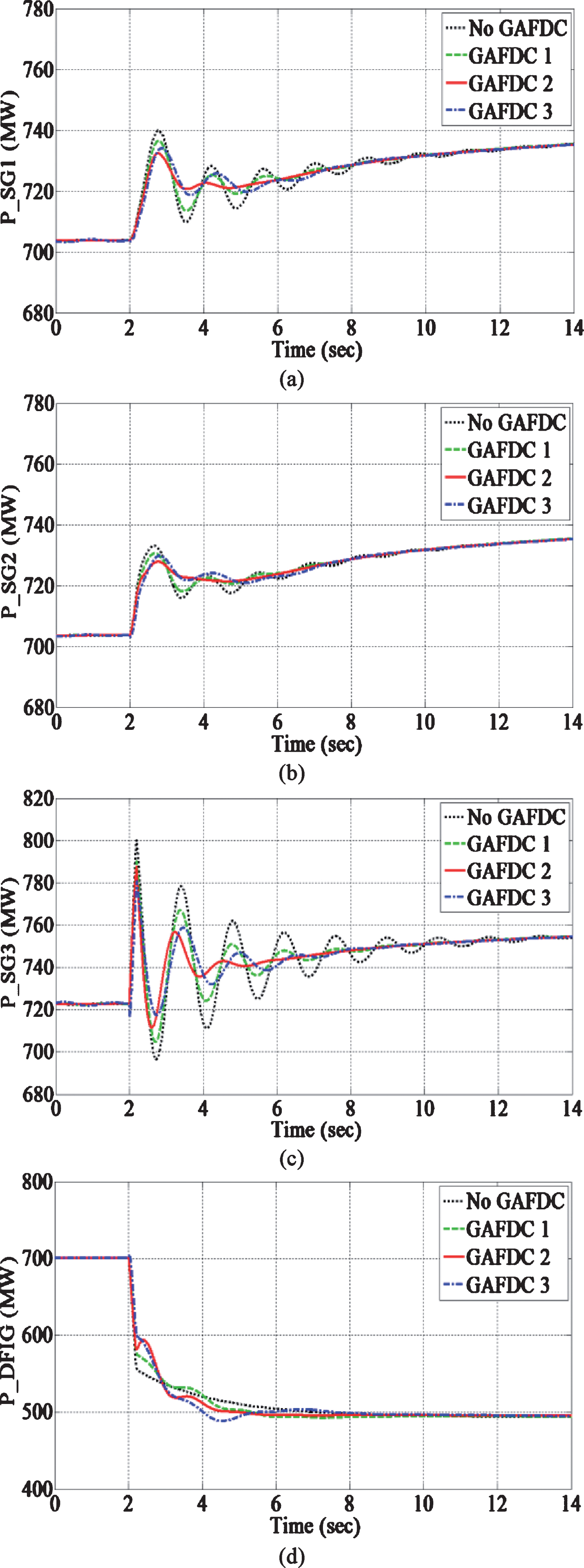
The dynamic behaviors of active powers: (a) PSG1 (b) PSG2 (c) PSG3 (d) PDFIG.

Power system oscillations: (a) δ21 (b) δ31 (c) Ptie.
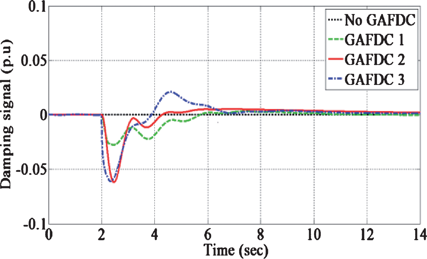
Comparison of damping signal (Pd) in Case 1.
In second case, a three-phase to ground short-circuit fault is considered to occur in the middle of one of the tie-lines between buses 7 and 9, and cleared after 100 ms by opening the circuit-breakers at two ends of the faulty line. This is a large disturbance under which the system’s operating point will be changed. Figs. 13 (a) and (b) compares the corresponding dynamic responses of DFIG in terms of active and reactive powers, respectively. It can be seen the DFIG equipped with the GAFDC 2 provides more active power immediately after the fault. On the other hand, the reactive power oscillations decreases with GAFDC 2 compared to others. In this condition, the angular swings of the synchronous generators decrease further when the DFIG is equipped with the GAFDC 2, as shown in Fig. 14.

Dynamic behaviors of DFIG in Case 2: (a) active power (b) reactive power.
Relative rotor angles of synchronous generators in Case 2: (a) δ21 (b) δ31.
In second case, a three-phase to ground short-circuit fault is considered to occur in the middle of one of the tie-lines between buses 7 and 9, and cleared after 100 ms by opening the circuit-breakers at two ends of the faulty line. This is a large disturbance under which the system’s operating point will be changed. Figs. 13 (a) and (b) compares the corresponding dynamic responses of DFIG in terms of active and reactive powers, respectively. It can be seen the DFIG equipped with the GAFDC 2 provides more active power immediately after the fault. On the other hand, the reactive power oscillations decreases with GAFDC 2 compared to others. In this condition, the angular swings of the synchronous generators decrease further when the DFIG is equipped with the GAFDC 2, as shown in Fig. 14.
The maximum angular swing of synchronous generators plays a very important role to keep the transient stability of power systems. In other words, the loss of synchronism or transient instability occurs when the maximum angular swing exceeds a certain limit, specified by±180°. For example, Fig. 15 shows that the system becomes unstable for the fault duration of 123 msec when the DFIG is not equipped with the damping controller while it can keep the transient stability with the proposed damping controller. To evaluate the effects of the proposed damping controller on the system transient stability, the repetitive simulations with increased values of the fault duration were carried out to obtain the critical clearing time (CCT) of the system. The CCT is the maximum fault duration for which the relative rotor angle of synchronous generators remains bounded or synchronism is preserved. The results of CCT are given in Table 4. It can be seen the GAFDC 3 leads to only 37% increase in the transient stability margin, while the GAFDC1 and the GAFDC2 increase it, 138% and 175%, respectively. Therefore, the GAFDC2 has a better effect on improving the system transient stability too.

Rotor angles for fault duration of 123 ms.
Comparing the CCTs
In this paper, an optimal and robust damping controller was proposed for DFIG wind turbines using the fuzzy logic approach. The parameters of the proposed fuzzy damping controller were optimally tuned using GA. Moreover, various feedback signals such as the local speed deviation, the rotor speed difference of synchronous generators, and the tie-line active power were tested as the feedback signals. The obtained results based on the minimum GA performance index were indicated that the rotor speed difference of the synchronous generators with higher participation factors in the system oscillation modes is the best feedback signal for the proposed damping controller. In addition, the effectiveness and robustness of the proposed controller were verified through several time domain simulations under different operating conditions and transient events. The simulation results revealed that the proposed controller can improve the power system oscillation damping for both the small and large disturbances. Moreover, it can increase the transient stability margin of the integrated power system.