
Abstract
The Maximum Power Point Tracking (MPPT) controller plays a vital role in maximizing power output from the solar Photovoltaic (PV) sources. The tracking efficiency of the MPPT controller is affected by a rapidly varying environmental condition. This paper presents a novel MPPT controller for standalone PV system based on a Neural Network (NN) and Gain-scheduled Proportional Integral (GS-PI) controller to track the fast-changing Maximum Power Point (MPP).The NN model is trained to predict the operating parameters of the PV array at which maximum power is generated. The gain scheduled PI controller parameters are optimally tuned with Real-coded Genetic Algorithm (RGA) to improve the controller performance. The developed MPPT controller is used to control the power converter in the solar PV system. The PV array along with the control scheme is developed using LabVIEW and Multisim environment. Further, the performance of the developed control strategy is experimentally validated with solar PV emulator and DC-DC boost converter under the varying irradiation conditions. The tracking performance of the developed MPPT controller is compared with the modified Perturb and Observe and NN+PI controller based MPPT controller. The experimental results reveal that the tracking performance of the developed MPPT technique is much improved and more accurate in MPP tracking.
Introduction
Environmental pollution caused due to fossil fuel and its depletion paved the way for alternate power generation schemes. One such alternative to the fossil fuel based power generation is the solar photovoltaic (PV) system based energy conversion system, which generates electricity from the sunlight [1]. The solar PV energy conversion system is a combination of the PV modules connected together either in series or parallel fashion to meet the desired load condition. The PV module exhibits highly non-linear characteristics and its maximum power generation depends on two major factors, namely, sunlight irradiation falling over it and the atmospheric temperature [1, 2]. The load receives maximum power from the PV module with the support of power converter circuits, which is controlled by the Maximum Power Point Tracking (MPPT) controller. The MPPT controller is employed between the PV module and load; to transfer maximum power from PV module to load. These MPPT controllers measure the instantaneous output voltage and current of the PV module to track the Maximum Power Point (MPP) by adjusting the duty cycle of the power converters [2, 3].
The commonly adopted MPPT techniques are the Perturb and Observe (P&O), Incremental Conductance and Extreme seeking control [4, 5] that use the instantaneous output data such as output voltage and current of the solar PV sources like PV module, string, and array to track the MPP. These MPPT algorithms are known as online MPPT algorithms. Among them, the P&O algorithm is the most commonly used MPPT technique due to its effortless tracking mechanism and less implementation cost [5]. The P&O algorithm tracks maximum output power of PV sources either by increasing or decreasing the voltage output of the PV sources in regular intervals. The tracking performance of the P&O algorithm depends on the step size of the PV sources reference voltage. For instance, if the large step size is used, P&O tracks the MPP at a faster rate but results in high steady state oscillation. On the other hand, if the smaller step size is used it reduces the steady state oscillation but its tracking speed is sluggish and leads to more power loss during rapidly varying irradiation conditions [5]. Fractional order open circuit voltage [4], fractional order short-circuit current [4], lookup table, and curve fitting methods come under the offline MPPT algorithm [6]. These offline MPPT algorithms depend on the key operating parameters of the PV sources at which maximum power is delivered. These offline MPPT algorithms require periodic load disconnection to measure the open-circuit voltage (VOC) and short-circuit current (ISC) of the PV sources. Hence, additional circuits are needed for the online measurement of VOC and ISC, which leads to implementation complexity. The operating point at which PV sources is delivering the maximum power is determined by multiplying measured VOC and ISC with the constant pre-determined voltage factor (KV) and current factor (KI). These predetermined factors are usually less than one. Under rapidly varying environmental conditions, measuring VOC and ISC parameters of the PV sources will be difficult and predetermined factors is not constant, which leads to poor tracking efficiency and leads to power loss [7, 8].
MPPT techniques based on Neural Networks (NN) were developed to improve the tracking performance and reduce power loss. The MPPT controller which combines a 2-level of Neural Network and a memory table is presented in [9], to track the optimal maximum power of the PV module under the rapidly varying irradiation condition. The memory table is optimized using the Genetic Algorithm (GA) to improve the MPPT controller performance. The MPPT controller based on NN for a standalone PV system has been discussed in [10, 11], which combines NN and Proportional Integral controller for tracking MPP. The MATLAB and Simulink simulation environment is used to develop the solar PV system along with NN MPPT controller. In [12] a NN MPPT controller has been proposed in which GA trained NN is combined with Proportional-Integral-Derivative controller to vary the duty cycle of the boost converter to improve the tracking performance. In the above NN approach, NN and Proportional-Integral-Derivative (PID) controller with fixed PID controller parameters is used, which cannot track MPP under the rapidly varying environmental condition [13].
To overcome the above-stated drawbacks of the MPPT controller, this paper aims to develop a Neural Network and Gain-scheduling (GS) Proportional-Integral (PI) (NN+GS-PI) MPPT controller for a standalone solar PV system developed in LabVIEW and Multisim environment. The standalone solar PV system consists of solar PV array, boost converter; NN+GS-PI MPPT controller and resistive load. The developed MPPT controller receives the irradiation and temperature level as an input to control the duty cycle of the DC-DC boost converter. A 640 W solar PV array emulator is used to test the developed MPPT controller. National Instruments (NI) based myRIO (Reconfigurable Input and Output) an FPGA based Data Acquisition (DAQ) card is used to deliver a faster response from the developed MPPT controller. The developed MPPT controller is tested under varying irradiation conditions and, the experimental results are discussed in the subsequent sections.
Structure of solar photovoltaic system
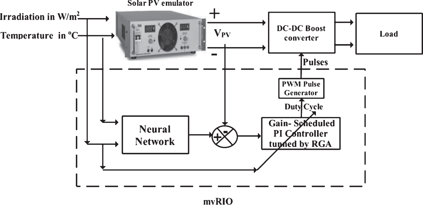
The block diagram representation of a standalone solar PV system is presented in Fig. 1 (a). A boost converter is used to connect load with solar PV array. The PV array power output is the product of the PV array voltage (VPV) and current (IPV). The PV module exhibits maximum power output at a point, which is called as Maximum Power Point as depicted in Fig. 1 (b). The MPPT controller which includes an MPPT algorithm, comparator, and the PWM pulse generator regulates the boost converter is incorporated between the PV array and load.
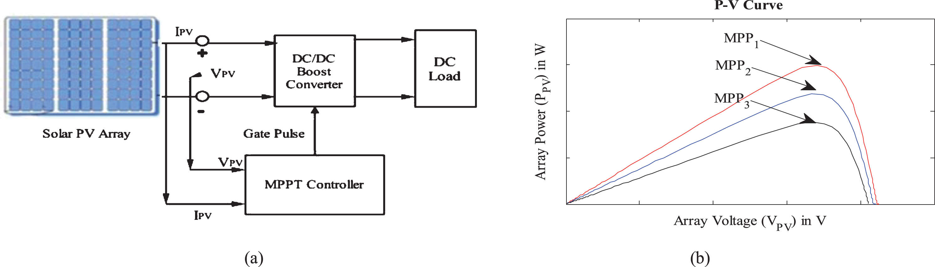
(a) The block diagram of standalone PV system, (b) Different Maximum power point under the different environmental conditions.
The output voltage and current of the PV array can be regulated to maximize power output from the PV array. The PV array operating voltage regulation is preferred due to its simplicity and accuracy, whereas the PV array operating current varies with sunlight irradiation and it requires complex control loop [14]. To track the MPP of the PV array, the operating voltage at MPP (VMPP) has to be predicted with the support of MPPT algorithm. The MPPT algorithm monitors the voltage (VPV) of the PV array and adjusts the duty cycle of the DC-DC boost converter, in turn, power output of the PV array is maximized. Therefore, MPPT controller has to be more efficient in predicting the operating voltage at MPP and to operate the PV array at the predicted MPP voltage by precisely varying the duty cycle of the boost converter in turn to improve the overall efficiency of the PV system. This work proposes a NN+GS-PI MPPT controller, the details of which are presented in the next section.
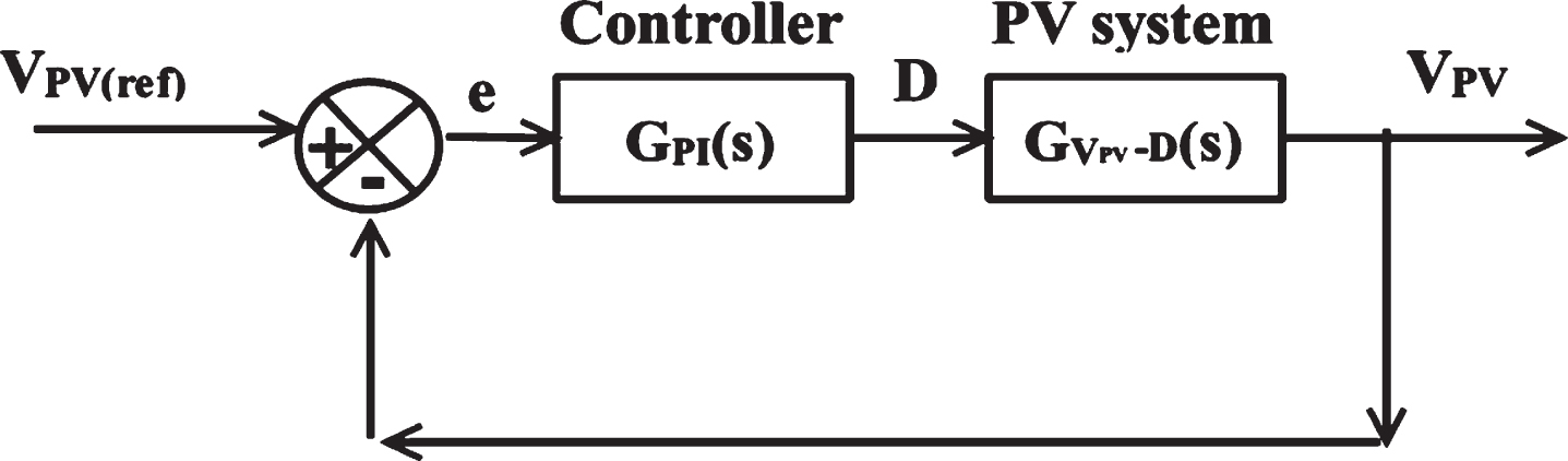
The block diagram of the proposed MPPT controller is presented in Fig. 2. The main objective of the proposed NN based MPPT controller is to predict reference operating voltage at MPP (VMPP(ref)) and regulate the operating voltage (VPV) of the solar PV array at which maximum power is delivered. The proposed MPPT controller is a combination of Neural Network and Gain-scheduled Proportional -Integral (GS-PI) controller. The NN+(GS-PI) MPPT controller is developed in two different stages Neural Network based Optimum Operating Voltage VMPP(ref)estimator Real coded Genetic Algorithm tuned Gain scheduled PI controller
Block diagram of the NN+(GS-PI) MPPT controller.
The Optimum Operating Voltage VMPP(ref) is estimated with Feed Forward Neural Network. The NN model is developed using the dataset having irradiation and temperature as input and the corresponding solar PV array output voltage (VMPP) at MPP as output. The developed NN model, receives the atmospheric temperature and irradiation of the sunlight falling over the solar PV array and estimates the VMPP(ref). The predicted VMPP(ref) is compared with the instantaneous solar PV array voltage (VPV) and its corresponding error e(t) signal is calculated using Equation (1).
Where KP- Proportional gain, Ti- Integral Time.
The error signal is given as the input to the GS-PI controller which generates the corresponding control signal UDutycycle(t) in turn to minimize the error signal. The generated control signal UDutycycle(t) is used to regulate the duty cycle of the DC-DC boost converter which is expressed in Equation (2). In general, the change in irradiation level is fast and drastic, compared to the change in temperature, which is slow and small. Apart from this, a change in the irradiation level affects the output current of the solar PV array. Therefore GS-PI controller uses the irradiation (Gc) of the PV array as the scheduling parameter and adjusts the PI controller parameters. The GS-PI controller used in this work is optimally tuned using Real-coded Genetic Algorithm (RGA) to improve the tracking performance.
The NN+GS-PI MPPT controller proposed in this work accurately estimates the MPP of the solar PV array and RGA tuned Gain-Scheduled PI controller improves the MPP tracking performance and speed. Therefore, the proposed MPPT controller is more suitable for the rapidly varying environmental conditions.
The architecture of the proposed Multilayer Feed-Forward (MLFF) network is shown in Fig. 3 [15–17]. The NN architecture for predicting Optimum reference Operating Voltage (VMPP(ref)) under the varying environmental conditions is a MLFF Network with back propagation learning. The proposed NN involves two stage of operations namely training and operational stage. In the training stage, the MLFF is trained to map the relationship between the environmental conditions (irradiation and temperature) and VMPP in the form of connecting weights.
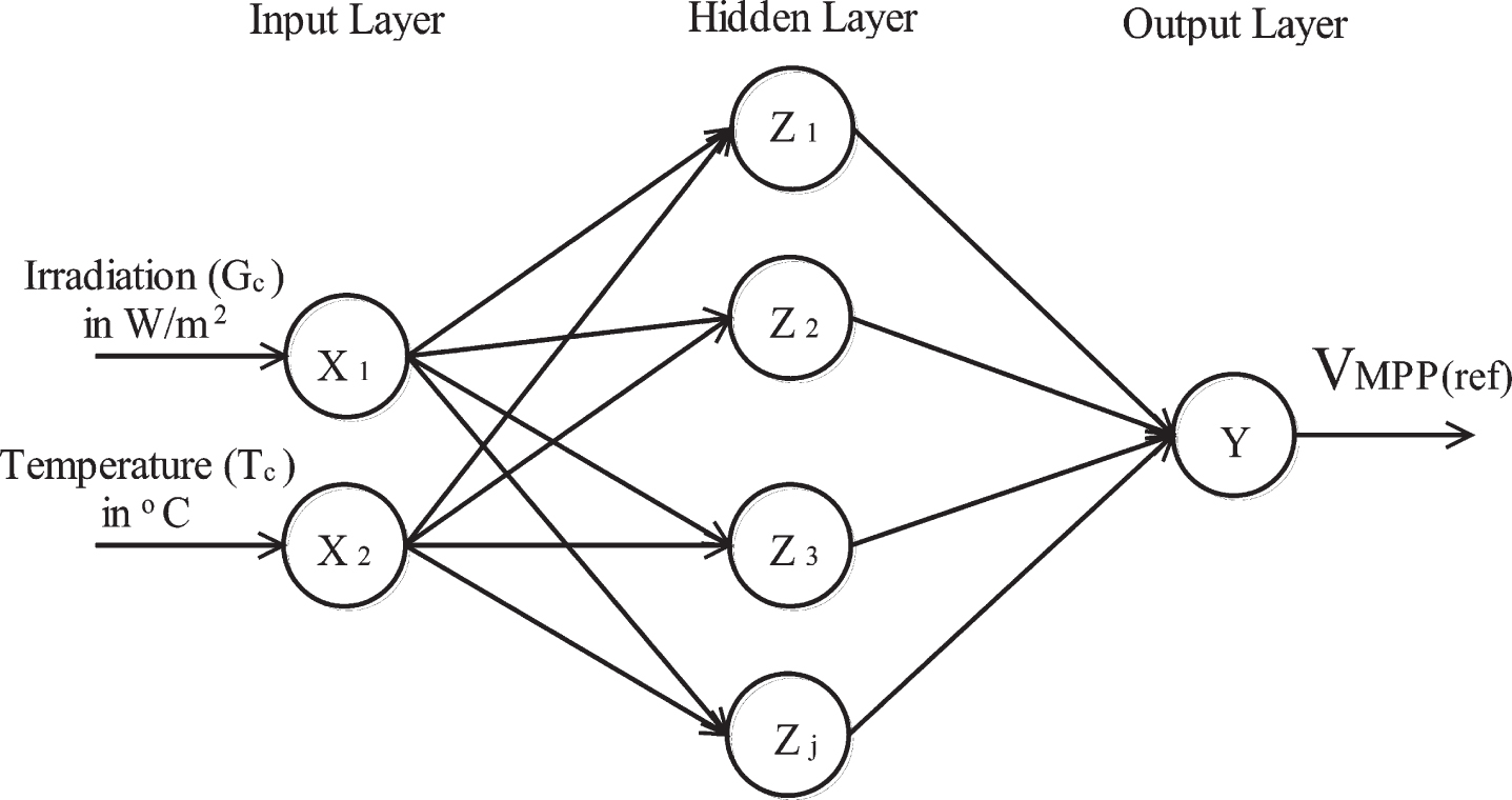
Architecture of the proposed multilayer feed-forward network.
The training data is obtained for various irradiation and temperature conditions. The weight adjustment is done by the supervisory learning algorithm. Most commonly used supervisory learning algorithm is the back propagation algorithm which involves feed-forward propagation, error back propagation, and weights updating or adjustment. The input data propagates through hidden layer and reaches the output layer. The output is calculated using a summation function, which is shown Equation (3). The Mean Square error (MSE) is used as the learning goal in this work, to evaluate the effectiveness of the network training, which is expressed in Equation (4). The network trained with small learning goal will have good performance and accuracy. The network trained with small learning goal will have good performance and accuracy.
The weight adjustment equations are given below in Equations (5)-(6).
x i – Total Number of Inputs; y j – Total Number of outputs
z h – Total Number of Hidden Neurons, d – Desrired output
k – iterations; η – Learning rate; δ – Deviation of output
b – bias
After the training stage, the developed neural network model is evaluated with a different input-output data set. Once the developed network is trained and tested, it is ready to predict the VMPP(ref) under the various operating conditions.
The power converter topology adapted is the DC-DC boost converter, which steps up the voltage from its source side to its load side. The proposed NN+GS-PI MPPT controller aims to operate the solar PV array at VMPP, either by increasing or decreasing the duty cycle of the DC-DC boost converter. Therefore, to analyze the above-stated operation, a transfer function between the solar PV array voltage (VPV) to the duty cycle (D) is derived. The equivalent circuit of solar PV system along with boost converter is presented in Fig. 4. The linearized model for the DC-DC boost converter is derived using the state averaging technique presented in [18]. The derived state-space model of boost converter representing the relationship between the solar PV array voltage (VP) and duty cycle (d) is given in Equation (7) and rewritten in transfer function is given by in Equation (8).
Equivalent circuit of solar photovoltaic system.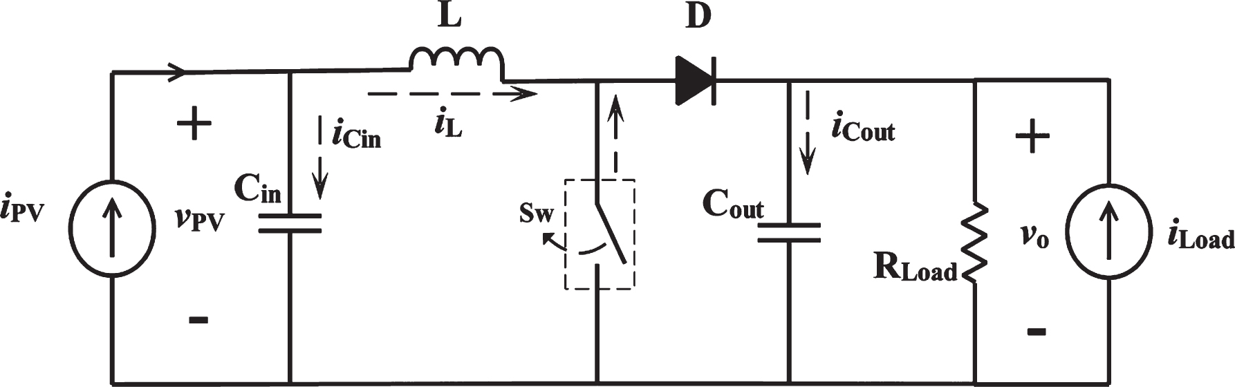
Where
vPV - PV array voltage; vo- DC-DC boost converter; i PV- PV array Current; r PV- PV array dynamic resistance; i L- Inductor current; i Load- Load Current; L-Inductor;Cin, Cout–Input and output Capacitor;D-Duty Cycle;
The control strategy adopted is a variable gain controller, which is called as gain-scheduled PI controller. The gain-scheduler selects the PI controller parameters by considering the irradiation level received by the solar PV array as the scheduling parameter. The selection of irradiation level as the scheduling parameter is due to the fact that variation in the irradiation level, drastically affects the current generation of the solar PV array. The PV array current (IPV) variation affects the PV array dynamic resistance (rPV), which in turn affects the damping factor (ξ) of the voltage regulation transfer function. The transfer function of the PI controller is given by
The performance of the controller is carried out by evaluating the performance criteria. This work focuses on tuning the PI controller parameters to improve the MPPT tracking performance of the NN+GS-PI MPPT controller, which is expressed as an optimization problem. The minimization of ITAE is the objective function, which is mathematically stated below
Where KP- Proportional Gain; KI- Integral Gain; ITAE-Integral of Time-weighted Absolute Error; T-Time Period.
The performance criteria chosen in this work is ITAE, which is more advantageous in evaluating the controller performance during set point change and load change. Real-Coded Genetic algorithm (RGA) is applied to find optimally tuned PI parameters. Various steps involved in finding the optimally tuned gain terms of the PI controller are discussed in the following sub-sections.
Genetic Algorithm (GA) finds an optimal solution to a problem by working on the population of the individual. Fitter individuals in each generation are selected by applying a selection strategy to create a new population. Random selection is applied over the individuals in new population [19], to form new solutions by applying genetic operators like cross-over and mutations. The Genetic algorithm finds the best individuals after passing several generations [19, 20], which represents the optimal solutions. The variables in the Binary coded GA (BGA) are expressed in binary numbers with the fixed length, which leads to difficulties in representing the variable in limited string length and resolution of the solution. To overcome the above-stated drawbacks in this paper; the floating point numbers are used to represent the decision variable [19].
During the implementation of RGA for PI controller tuning, decision variable representation and fitness function formation [19] are the two major factors. The proportional and integral gains are the optimization variables which are represented as individual in the population. These decision variables are expressed as floating numbers [19, 21] in turn to reduce size of the computational memory and data storage.
Initial value of all the variables in the population are initialized randomly based on the Equation (11).
The important step carried out in the GA is the selection of fitter individuals from the present generation. The fitness value of each individual in the population is calculated by the fitness function as expressed in Equation (12).
Where ‘K’ is the amplification factor.
Individuals with high fitness value are chosen for the next generation. Tournament selection strategy [19] is used in this work; the property of the GA is a global search, which is carried with the support of crossover genetic operator. Crossover operator combines substructure of the two parent chromosomes, with crossover probability range of 0.6-0.9 [19, 21]. The Blend Crossover operation (BLX-α) [19, 20] is chosen in this work, which is shown in Equation (13). New individuals are selected from the fittest parents’ u1 and u2 and their corresponding offspring ‘y’ is representation is given below [19, 20].
Where
Mutation is a genetic operator, which helps in introducing new genetic materials into the population[19, 21]. The variables of parents in the current population are modified by mutation with small probability [19, 21]. Uniform mutation is applied, which helps to align the variables to a uniform random number between the upper and lower limit of the variable.
This section presents the details of the experiments conducted on the PV array using the proposed MPPT controller. To evaluate the tracking performance of the NN+GS-PI MPPT controller, the solar PV array is operated at Standard Test Condition (STC) and varying irradiation level. Tracking time and static MPPT efficiency of the developed MPPT controller are evaluated and compared with modified (P&O). The system is further tested with randomly varying irradiation level and dynamic MPPT efficiency is estimated and the results are presented.
Hardware setup
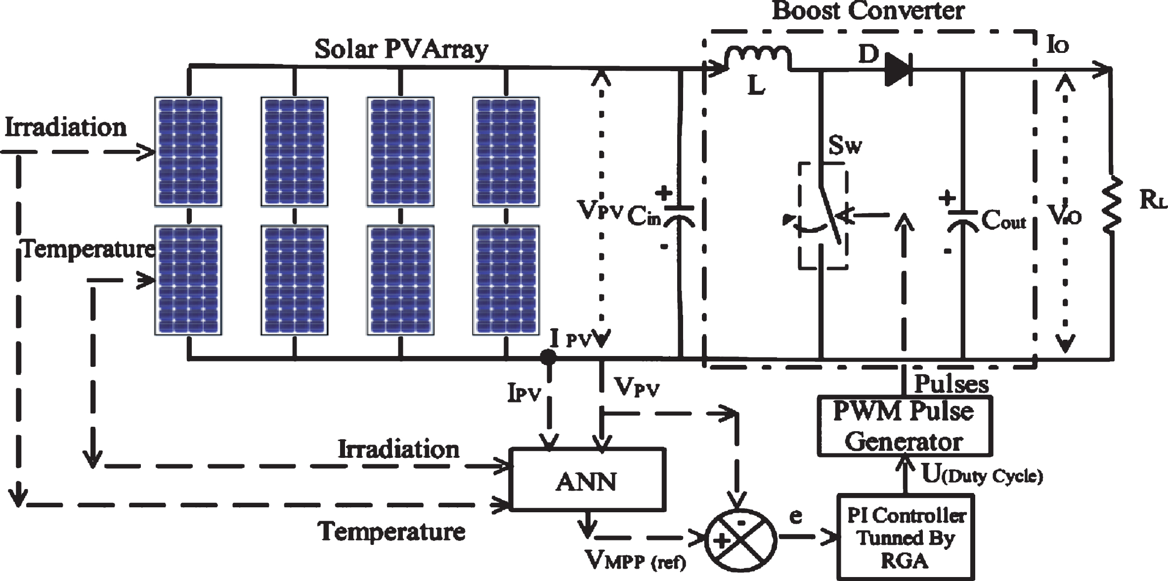
The overall tracking performance of the NN+GS-PI MPPT controller is evaluated in a solar PV test bed consisting of programmable DC supply based solar PV array emulator, a boost converter and load. The block diagram representation of the experimental setup along with the NN+GS-PI MPPT controller is depicted in Fig. 5.
Block diagram representation of the experimental setup.
A solar PV array developed in Multisim is used as the PV source. The electrical parameters of a single Sukam PV module are VOC = 21.1 V, ISC=5.2 A, VMPP = 17 . 4V, IMPP = 4 .6A and PMPP = 80W. Two modules are interconnected together in the series fashion and four sets of these serially connected modules are connected together in parallel fashion to get the solar PV array with V, ISC = 20.8 A and guaranteed Peak power of 640 W. The developed solar PV array model is co-emulated with the LabVIEW and implemented in the solar PV emulator. Figure 6 illustrates the emulation model of the solar PV array in Multisim and; Fig. 7 shows the photograph of the hardware setup used in this work. The emulation of solar PV array along with the NN+GS-PI MPPT controller is carried out for different environmental conditions. The hardware implementation of the developed MPPT controller is carried out with the National Instruments-myRIO (my Reconfigurable I/O) for faster controller response. The performance of proposed MPPT controller is evaluated using the static and dynamic tracking efficiency. The proposed NN+GS-PI MPPT controller is compared with modified P&O and NN+PI controller MPPT controller under STC and a varying irradiation condition.
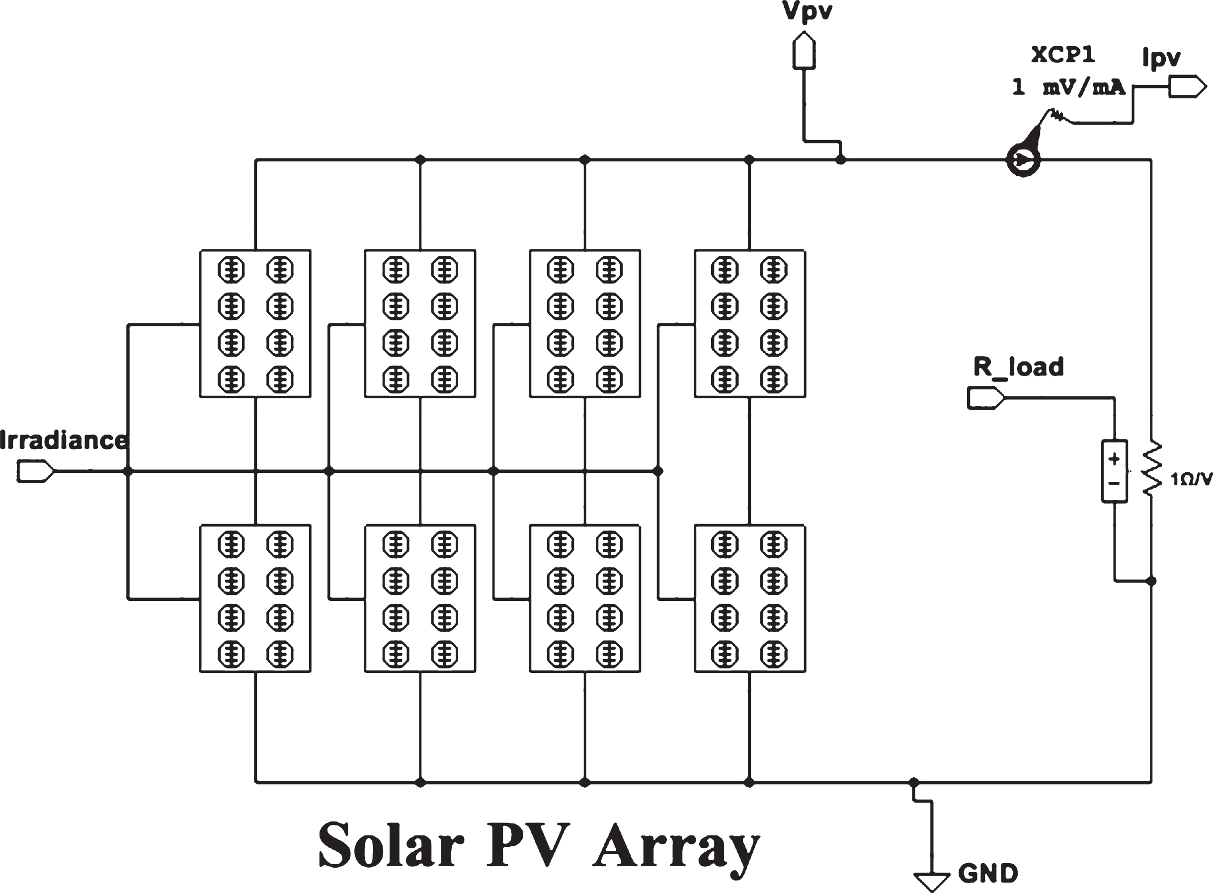
Solar PV array in multisim.
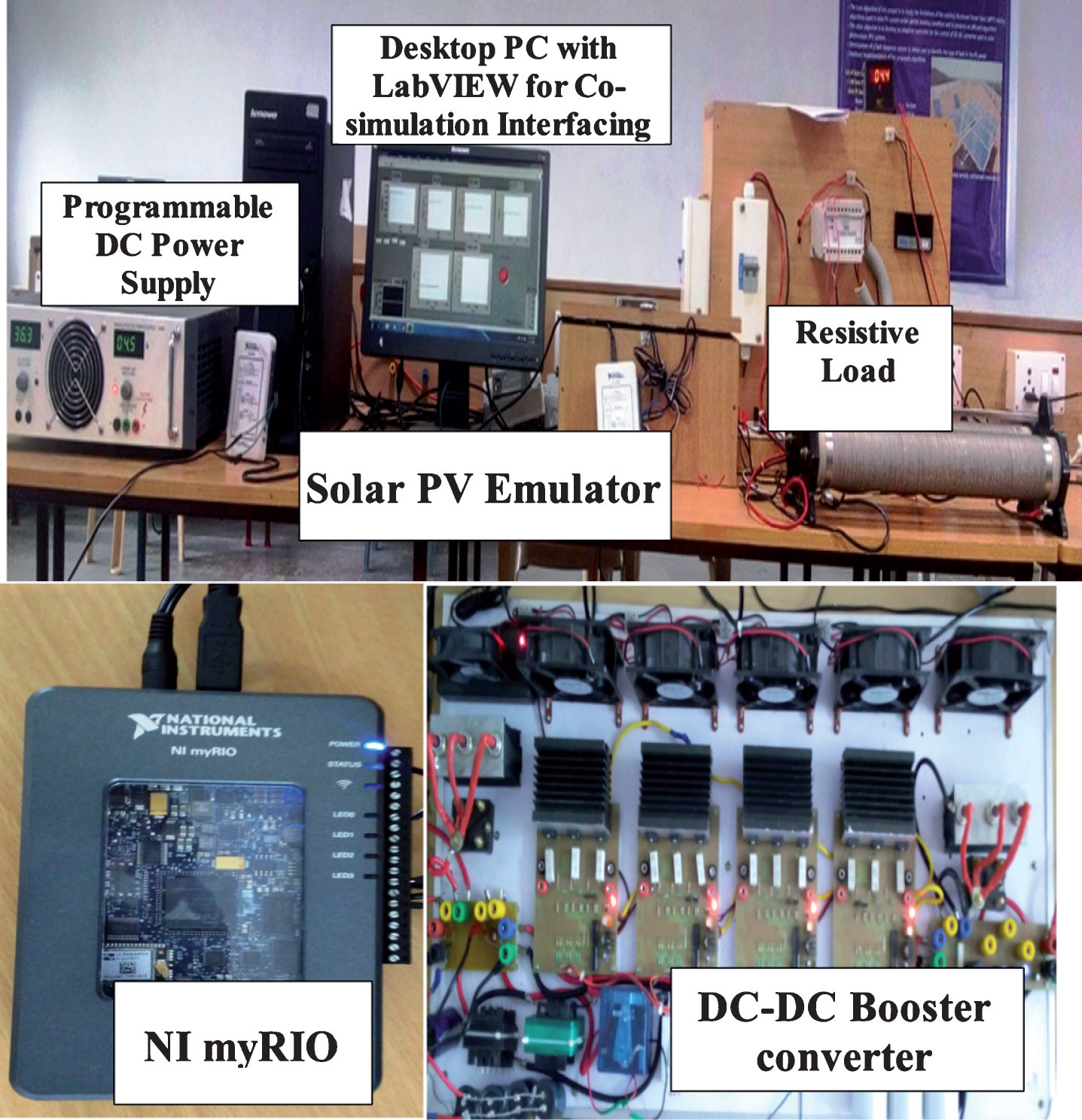
Experimental setup.
The NN model is developed using the experimental data collected from the test bed. The solar PV emulator is operated under different environmental conditions (irradiation and temperature) and characteristics curve is plotted. From the characteristics curve, PV array voltage output (VMPP) values are measured. Totally 1000 dataset of irradiation and temperature level along with the PV array voltage output (VMPP) were collected, out of which 750 dataset are used for training and 250 dataset for testing. The hidden layer neurons count is selected on the trial and error basis. The activation functions used in the hidden and output neuron are tangent hyperbolic and linear function respectively. Network training is carried out with Levenberg - Marquard algorithm and until learning goal reaches the MSE of 0.0001. The testing dataset is used to evaluate the training performance of the developed network, thereby preventing the network from overtraining problem. The development of NN is carried out with MATLAB neural networks toolbox. The developed NN model showed the best performance with 10 hidden layers and reached an MSE of 9.8017e-5 in 390 epochs, which is illustrated in Fig. 8 (a). On completion of training and testing, the developed neural network is capable of estimating VMPP(ref). Figure 8 (b).depicts the predicted VMPP output of the NN model after completing the testing phase. The estimated VMPP value of developed neural network matches with measured VMPP output of the emulated PV array.
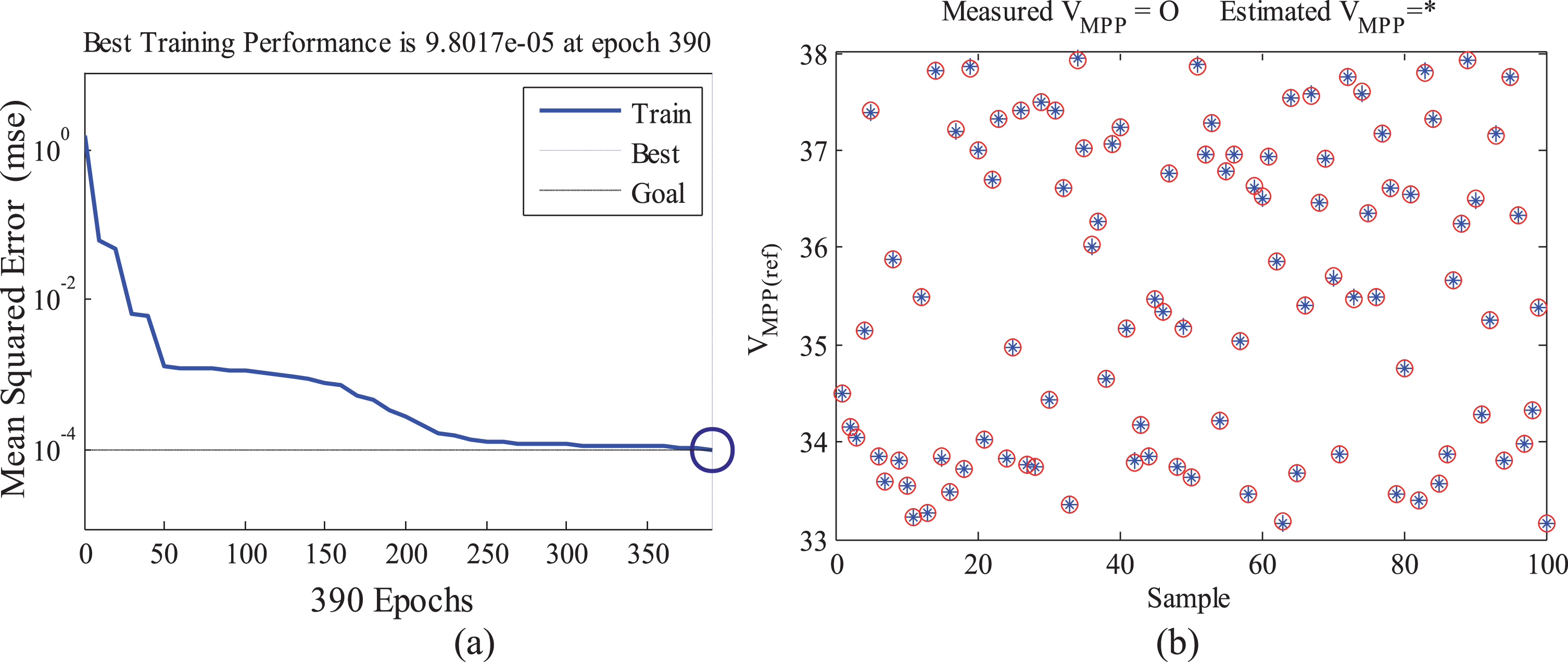
(a) Training Performance of NN, (b) Estimated VMPP Output.
The gain-scheduled PI controller chooses the PI controller parameters with reference to the irradiation level as a scheduler. The specifications of the boost converter are an inductor of 500 mH, a capacitor of 330μf and a resistance of 3.6 ohms. Based on the above-mentioned parameter the voltage regulation transfer function is derived for different irradiation ranges from 1000 W/m2- 700 W/m2 in steps of 100 W/m2. The derived transfer function at 1000 W/m2 is given in Equation (14).
With the derived transfer function closed loop structure is built, which is illustrated in Fig. 9. The closed loop structure is used to tune the PI controller using the proposed RGA algorithm. The optimization parameter ranges are 0.01 < KP < 50 and 0.01 < KI < 100. The best tuning results are attained with the following RGA control parameters, population size - 50, generation - 100, Cross-over Probability (PC) - 0.6 and Mutation Probability (Pm) - 0.05.The optimal values of PI controller determined by RGA are KP - 0 .241 and TI - 0.027. For comparison the system performance is evaluated with PI controller which is tuned using Ziegler-Nicholas that has KP - 0 .412 and TI - 0 .35 values. Figure 10 shows the closed loop performance of the voltage regulation loop with PI controller tuned using RGA and Ziegler-Nicolas for the Standard Test Condition STC [4], at which irradiation level is 1000 W/m2 and temperature level is 25 °C. The Proposed RGA has a minimum setting time of 1.12 milliseconds and with no peak overshoot. Therefore, the performance of the system is improved with control parameters obtained using RGA controller. The estimated PI controller parameters using RGA with different irradiation is shown in Table 1.
Block diagram of the developed control loop structure.

System performance with PI controller tuned using RGA and Ziegler-Nicolas.
PI controller parameters estimated using RGA
The experimental setup is used to evaluate the performance of NN+GS-PI MPPT controller at STC. Figure 11 (a) presents the P-V characteristics of the emulated solar PV array at STC. The maximum power output of the emulated solar PV array is 640.8 W at STC. An irradiation level of 1000 W/m2 and temperature level of 25 °C was set on the emulator and the developed MPPT controller calculated the VMPP(ref)using neural network as 34.51 V. The gain scheduling PI controller schedules the parameters as; KP = 0 . 241 and TI = 0.027with respect to the irradiation level. Under this conditions, the developed NN+GS-PI MPPT controller starts to track the calculated VMPP(ref) by increasing the duty cycle value and tracks the MPP in fewer iterations, as depicted in Fig. 11 (b). The conventional NN+PI MPPT controller tracks the MPP with the PI controller values KP = 0 . 412 and TI = 0 . 35. Contrary to it, the modified P&O algorithm [5] either increase or decrease the duty cycle in two different steps of duty cycle. The step size of 0.01 or 0.005 is chosen based on the pre-defined error limit. The modified P&O algorithm starts the iteration with initial duty cycle value of 0.1 and increases the duty cycle value in steps till it reaches the MPP. The developed MPPT controller tracks the MPP faster with lesser oscillation, when compared with NN+PI and modified P&O. Figure 11 (c) depicts the comparison between power output of PV array with modified P&O MPPT and NN+GS-PI MPPT controller. The maximum power tracked by NN+GS-PI controller from the solar PV array is 638.3 W. The NN+GS-PI MPPT controller takes 8.1 seconds to reach the MPP, whereas NN+PI MPPT controller takes 17.5 seconds and tracks 635.2 W. The modified P&O takes 15.1 seconds to track a maximum power output of 633.7 W. The output oscillation of the NN+GS-PI MPPT controller is±2 W, which is lesser when compared with output oscillation of NN+PI and modified P&O algorithm which is evident in Fig. 11 (d).
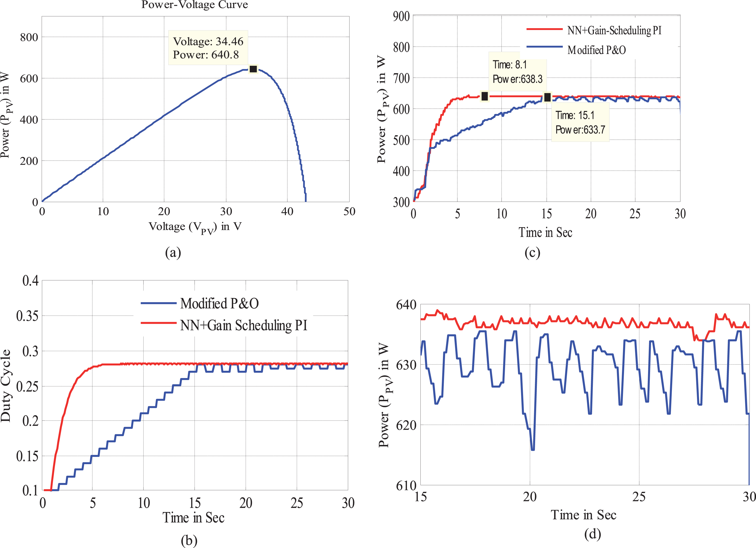
(a) P-V characteristics of the PV array at STC, (b). Duty cycle output at STC, (c) Power output of the PV array at STC. (d) Power output oscillation of the PV array at STC.
Next, the performance of the NN+GS-PI MPPT controller is evaluated under varying irradiation conditions. The solar PV array is emulated with the varying irradiation level and at a constant temperature. The irradiation level is decreased in steps of 100 W/m2, from 1000 W/m2 to 700 W/m2 and then increased vice versa in the interval of 20 seconds and temperature level is 25°C. Figures 12 (a) and (b) presents the varying irradiation level and corresponding varying duty cycle of the NN+GS-PI controller. The estimation of VMPP(ref) by NN and its subsequent PV array voltage VMPP at MPP tracking is illustrated in Figs. 12 (c) and (d) depicts the power output of the PV array along with NN+GS-PI MPPT controller.

(a) Changes in irradiation at constant temperature of 25°C, (b) Variation in duty cycle under varying irradiation, (c) VMPP(ref) prediction by NN and VMPP tracked output voltage under varying irradiation, (d) Power output of the PV array with proposed NN+GS-PI MPPT controller.
The absolute error of the predicted VMPP is calculated using Equation (15). The calculated absolute error is shown in Table 2.
The NN+GS-PI MPPT controller responds instantly to changes in irradiation level by predicting the VMPP(ref) and loading the corresponding PI controller parameters corresponding to the scheduler. The conventional NN+PI tracks predicts the VMPP(ref) and with the constant PI controller values KP = 0.412 and TI = 0.35 responds to the irradiation level changes. With the estimated value of VMPP(ref) and appropriate PI controller parameters, the developed MPPT controller takes 4 seconds to track the irradiation changes. The modified P&O and conventional NN+PI MPPT controller takes more than 9 seconds to respond to the irradiation change, which is shown in Fig. 13 (a) and represented in Table 3.
Comparison of estimated VMPP of the PV array between the developed MPPT controller and Modified P&O MPPT algorithm
Tracking Time comparison between the developed MPPT controller and Modified P&O MPPT algorithm
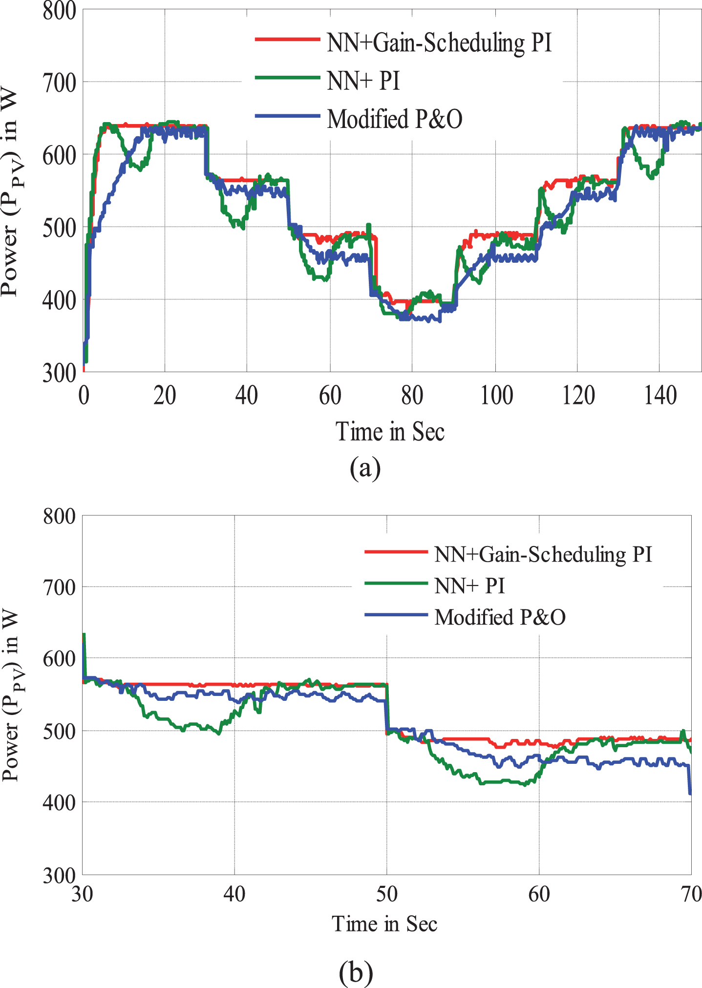
(a) Comparison of power output of the PV array along with proposed NN+GS-PI MPPT controller and conventional MPPT controller, (b) Power tracking loss comparison between proposed and conventional MPPT controller.
As illustrated in Fig. 13 (b) the modified P&O and conventional NN+PI MPPT tracks lesser power from PV array, when compared to the NN+GS-PI MPPT controller. The tracking loss is mainly due to the inaccuracy in predicting VMPP(ref) and poor tracking performance of single PI controller. The NN+GS-PI MPPT controller overcomes the above-mentioned difficulties by accurately predicting VMPP(ref) using NN, which has a maximum absolute error of 0.53 and scheduling PI controller parameters with irradiation level as a scheduler.
The static MPPT tracking efficiency of the NN+GS-PI MPPT controller is calculated using Equation (16).
Comparison of power output of the PV array

Dynamically varying irradiation level.

Power output of the PV array with developed NN+GS-PI MPPT controller.
The results show that the developed NN+GS-PI controller is accurate in estimating the operating voltage (VMPP(ref)) and Gain scheduled PI controller tracks maximum power of PV array faster and with lesser power loss than the modified P&O algorithm and NN+PI MPPT controller. Apart from this, the overall static and dynamic MPPT efficiency of the developed MPPT controller is high and has lesser steady state oscillation around MPP.
An improved NN+GS-PI MPPT controller with gain scheduled PI controller is proposed in this work. The developed NN+GS-PI MPPT controller is a combination of neural network and gain scheduled PI controller. The PV array along with the proposed MPPT controller is developed in LabVIEW and Multisim environment. The hardware setup is developed with PV array emulator along with DC-DC boost converter. The developed experimental setup along with the developed NN+GS-PI MPPT controller is emulated under the different irradiation conditions. The developed MPPT controller tracks the MPP with the maximum tracking time of 8.1 seconds, which is comparatively faster than other conventional techniques. The overall efficiency of the developed NN+GS-PI MPPT controller is better and tracks MPP quickly under varying irradiation with lesser output power oscillations around MPP. Hence, the proposed MPPT algorithm can be expanded for the tracking solar PV system under partial shaded conditions.