
Abstract
This paper presents a novel adaptive fuzzy sliding mode (AFSM) control scheme for a vehicle steer-by-wire (SbW) system. Initially, the dynamics of the SbW system are described by a second-order differential equation where the Coulomb friction and the self-aligning torque are treated as external disturbances. Furthermore, an AFSM controller is designed for the SbW system, which utilizes an adaptive law to estimate both the Coulomb friction and the self-aligning torque, a sliding mode control component to deal with the parametric uncertainties and unmodeled dynamics, and a fuzzy strategy to strike a good balance between the chattering-alleviation and the tracking precision. The stability of the control system is verified in the sense of Lyapunov, and the selection of control parameters is provided in detail. Lastly, experiments are carried out under various road conditions. The experimental results demonstrate that the developed AFSM controller possesses superiority in terms of higher tracking accuracy, stronger robustness and a better balance between the control precision and smoothness in comparison with a conventional sliding mode (CSM) controller and a boundary layer-based adaptive sliding mode (BLASM) controller.
Introduction
With the development of modern automobile industry, the drive-by-wire (DbW) technology is playing a more and more significant role due to its remarkable benefits. The basic idea of DbW is to utilize electromechanical actuators and electronic control systems to replace conventional mechanical linkages existing in vehicles [1]. The implementation of DbW in different parts of a vehicle leads to different by-wire technologies, such as steer-by-wire (SbW) [2, 3], brake-by-wire [4, 5], shift-by-wire [6] and throttle-by-wire [7]. As an important part of the DbW technology, an SbW system utilizes a steering motor instead of the driver to generate steering torques to steer front wheels, a feedback motor to provide feedback torques for the driver to feel the interactions between the front wheels and the road surface, and a closed-loop control system to control the SbW system such that the vehicle can track a road path accurately [8]. The SbW technology possesses several noteworthy advantages compared with conventional vehicle steering systems, such as the enhancement of vehicles’ maneuverability due to the flexible adjusting of steering motor inputs, the reduction of frictions and vibrations caused by conventional mechanical transmission, and the improvement of drivers’ safety under front-end car collisions due to the removal of steering columns [9, 10]. Furthermore, unmanned driving is the future trend of transportation, and the SbW technology is one of the key foundations of unmanned driving. Compared with conventional steering systems, SbW systems utilize steering motors to generate the steering torque instead of drivers. The motor control procedure affects the steering performance of an SbW-equipped vehicle significantly. This is the reason why we mainly focus on the control design for SbW systems in this paper.
For the robust control of an SbW system, accurate dynamic modeling of the SbW system is of great importance, which has been investigated by many researchers. For instance, detailed plant models are identified to describe the dynamics of a load sensing valve spool, a two-stage proportional electro-hydraulic valve and a translational actuator cylinder existing in an electro-hydraulic SbW system [11]. In [12], considering the tire forces and the yaw motion of a vehicle, a detailed state equation is proposed to describe the vehicle model and the steering characteristics including over steering, under steering and neutral steering. On the basis of accurate dynamic modeling, robust control design for an SbW system also plays a key role. Much research has been conducted on the control schemes of vehicle SbW systems. For instance, a continuous time-varying tracking controller is designed for an SbW equipped vehicle such that the tracking error can be exponentially forced to a neighbourhood of zero while guaranteeing an adjustable steering ‘feel’ [14]. In [15], a fault-tolerant model predictive control scheme is proposed for a vehicle SbW system, where a fault detection observer is constructed to estimate the fault in the SbW system, and an active model predictive control input is designed to compensate for the effect of the actuator faults.
In this paper, we develop an adaptive fuzzy sliding mode (AFSM) controller for vehicle SbW systems, where a sliding mode control input is used to deal with system uncertainties and unmodeled dynamics, an adaptive law is adopted to estimate the self-aligning torques and the Coulomb friction, and a fuzzy scheme is designed to alleviate the chattering caused by the sliding mode control component while maintaining high tracking accuracy. Therefore, the advantages of the three control strategies can be integrated and the control performance of the SbW system can be improved to a large extent.
Sliding mode control is a variable structure control scheme with high control precision and strong robustness against system uncertainties [16]. Due to its remarkable advantages, sliding mode control has been widely used in various applications, such as [17–19]. Adaptive control is a control strategy with flexible design approach, which is especially suitable for systems with time-varying dynamics [20–22]. For instance, a receding-horizon adaptive control scheme is proposed to reduce laser beam jitter, where the control command is derived from a receding-horizon performance index and a recursive least-squares adaptive lattice filter is adopted to perform a required prediction [23]. As an intelligent control scheme designed by the utilization of expert knowledge, fuzzy control is another powerful control strategy widely used in many applications [24–27]. Specifically, an interval type-2 fuzzy system and a sliding mode control technique are combined to develop a hybrid control scheme to address the tracking problem of uncertain hyperchaotic systems [28]. Sliding mode, adaptive and fuzzy control methods all possess unique merits. However, the combination of them is still rare in vehicle SbW systems. Thus, it motivates us to combine them and integrate their advantages in the implementation of SbW systems.
The remaining part of this paper is organized as follows. In Section 2, a plant model is given to describe the dynamics of our SbW system. In Section 3, the AFSM controller is designed for the SbW system. The stability of the control system is proved in the sense of Lyapunov and the guidelines for control parameters selection are provided in detail. In Section 4, experimental results of the proposed AFSM controller, a conventional sliding mode (CSM) controller and a boundary layer-based adaptive sliding mode (BLASM) controller are shown, compared and analysed. Finally, Section 5 concludes this paper.
Plant modeling
Our experimental platform of a vehicle SbW system is shown in Fig. 1. From it we can see that the steering column in conventional steering systems is removed. Instead, a steering motor (Mitsubishi HF-SP102) is used to generate steering torques. The torque is then used to steer the front wheels through a transmission system consisting of a gear head, a pinion-and-rack gear box and steering arms. An angle sensor (MoTeC) is attached to the steering wheel to measure the rotation angle of the steering wheel. Multiplying this angle measurement by a gain from the steering wheel to the front wheels yields the reference signal of the closed-loop control system. Another angle sensor (MoTeC) is attached to the pinion to measure the rotation angle of the pinion. Similarly, multiplying this angle measurement by a gain from the pinion to the front wheels yields the steering angle of front wheels, i.e., the system output. The reason why we use this way to obtain the steering angle of front wheels is that limited by our experimental setup, we cannot measure the steering angle of front wheels directly. The designed control law to control the SbW system is implemented by MATLAB Real-Time Workshops installed on an HP computer. An Advantech PCI multi-function card is used to collect sensor measurement signals and generate real-time control input signals. A servo driver is used to convert the control input signals into current signals to drive the steering motor.
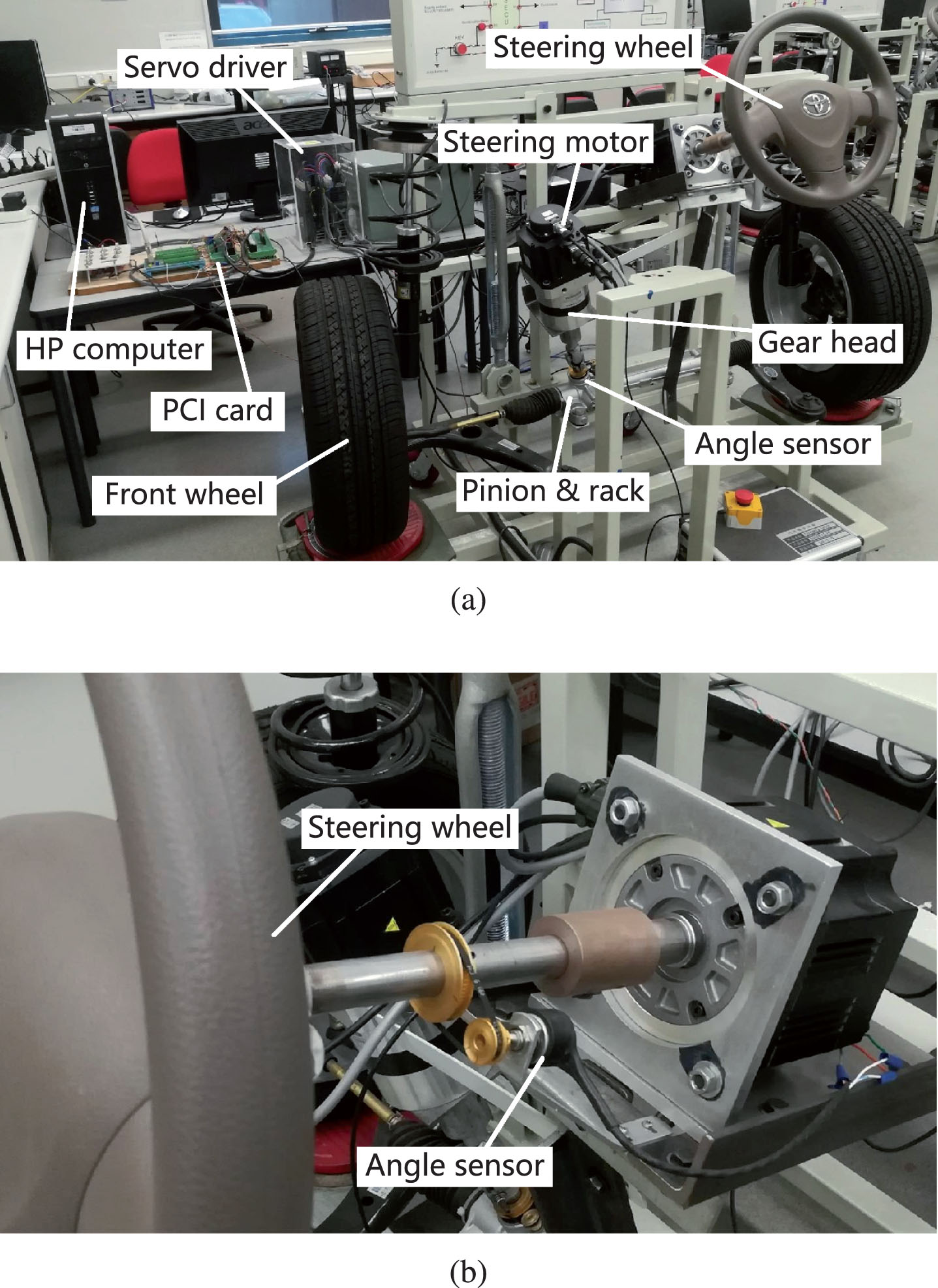
Experimental platform of a vehicle SbW system.
According to [8], the dynamic model of the vehicle SbW system is expressed as:
In our experimental platform, the bandwidth of the steering motor servo driver is much higher than that of the steering system. Hence, it can be assumed that the steering torque generated by the steering motor is proportional to the input voltage of the steering motor. The transmission gains of the gear head, the pinion-and-rack gear box and the steering arms are also fairly constant in time. Therefore, the parameter b is simply treated as a constant for control design. For other parameters, the parametric uncertainties are considered with the nominal values and the upper bounds given by
Under the assumption of a small front wheel slip angle, the self-aligning torque τ can usually be modeled by a hyperbolic tangent function multiplied with a time-varying coefficient with respect to road conditions [12, 13]. Therefore, we can identify the dynamic model of the self-aligning torque τ as follows:
From Fig. 1 we can see that, limited by our experimental setup, the front wheels cannot be driven to generate forward velocities. Thus, the front wheels cannot be exerted by real self-aligning torques in experiments. In order to introduce the effect of self-aligning torques, we can artificially generate the following voltage signal as an input to the steering motor:
Our aim is to design a robust controller for vehicle SbW systems such that the steering angle of front wheels can track the reference command accurately under various road paths and conditions. To achieve this goal, an AFSM controller is designed to deal with the parametric uncertainties and unmodeled dynamics, estimate the Coulomb friction and the self-aligning torque, and strike a good balance between the control precision and smoothness. A CSM controller and a BLASM controller are presented for comparison.
Adaptive sliding mode control design
Define the tracking error e as
After setting the definitions of the tracking error e and the sliding variable s, we can start to design the adaptive sliding mode control input. This control input consists of 3 components, namely, the equivalent control component u eq , the reaching control component u r and the adaptive control component u c . Specifically, the design of u eq and u r belongs to the sliding mode control design, which is used to handle the nominal dynamic model, force the system trajectory to ‘slide’ along the sliding surface and make the tracking errors converge to zero or at least a small region. The effect of u c is to adaptively estimate and compensate for the Coulomb friction and the self-aligning torque such that the tracking accuracy can be further improved. The design of u eq and u r is based on [16] and u c can be obtained according to [29].
First, we temporarily neglect the parametric uncertainties and nonlinear terms existing in the plant model, namely, we assume that F c = 0, d = 0 and τ = 0. Then, solving the following sliding mode dynamics
Furthermore, in order to guarantee the robustness against parametric uncertainties and unmodeled dynamics, a reaching control input signal u r [16] is introduced here as
Lastly, to exclusively compensate for the effect of the Coulomb friction F c and the self-aligning torque τ, a control input u c is designed as
Lemma 1: Consider the SbW system given by (1) with the parametric uncertainties as shown in (2) and under the control law
Proof: Choose the Lyapunov function as
In our system, the coefficient of Coulomb frictions μ and the coefficient of self-aligning torques η can be treated as constants for a specific road condition. In addition, the road condition for a normal running vehicle usually changes fast enough in reality. Thus, it can be assumed that
Remark 1: From (11) we can see that there exists a discontinuous term Msign (s)/b in the control input, which will bring unwanted chattering to the system and deteriorate the control performance. A conventional way to alleviate the chattering is to use the so-called boundary layer technique [30], which adopts the following saturation function sat (s) to replace the standard signum function sign (s):
To strike a better balance between the chattering-alleviation and the tracking accuracy in comparison with conventional boundary layer techniques, a fuzzy system is proposed to replace the discontinuous term sign (s) existing in the control input rather than the saturation function. The design of the fuzzy system is based on [31].
In the fuzzy system, the sliding variable s (t) defined in (8) and its alteration Δ
s
are set as the inputs, and a function fuzzy (s) is used to represent the output. The output fuzzy (s) is then generated to replace the discontinuous term sign (s) as shown in (11). Note that for our experimental platform, a fixed-step solver with a sampling period T
s
= 0.001 s are used to implement the control law. Thus, the alteration of s (t) can be obtained by multiplying the first-order derivative of s (t) with the sampling period T
s
, namely,
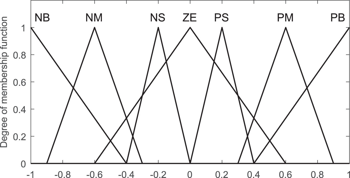
In our fuzzy system, the membership functions (MFs) of the input variables s (t) and Δ s (t) are set with the statuses of negative (N), zero (Z) and positive (P). The output MFs are set with the statuses of negative big (NB), negative medium (NM), negative small (NS), zero (ZE), positive small (PS), positive medium (PM) and positive big (PB). Then only 9 fuzzy rules are required for the fuzzy system, which reduces the complexity of the control algorithm and the computation load of the hardware but can still guarantee the chattering-alleviation effect. The domain of discourse for s (t), Δ s (t) and fuzzy (s) are set as [-1, 1]. Triangular types of MFs are chosen for the input and output variables. It is noted that the setting of ‘Z’ in the inputs and ‘ZE’ in the output influences the chattering-alleviation effect to a large extent. After many times of adjusting in experiments, we set the MFs of the inputs and the output as shown in Figs. 2 and 3 such that a nearly optimised balance between the control smoothness and the tracking accuracy can be obtained.

Membership function setting for inputs s (t) and Δ s (t).
After the setting of MFs, fuzzy rules should also be given to activate the fuzzy system, which are usually expressed in the ‘IF–THEN’ format. Here, 9 fuzzy rules are straightly given and shown as follows: IF s (t) is N AND Δ
s
(t) is N THEN fuzzy (s) is NB IF s (t) is N AND Δ
s
(t) is Z THEN fuzzy (s) is NB IF s (t) is N AND Δ
s
(t) is P THEN fuzzy (s) is NM IF s (t) is Z AND Δ
s
(t) is N THEN fuzzy (s) is NS IF s (t) is Z AND Δ
s
(t) is Z THEN fuzzy (s) is ZE IF s (t) is Z AND Δ
s
(t) is P THEN fuzzy (s) is PS IF s (t) is P AND Δ
s
(t) is N THEN fuzzy (s) is PM IF s (t) is P AND Δ
s
(t) is Z THEN fuzzy (s) is PB IF s (t) is P AND Δ
s
(t) is P THEN fuzzy (s) is PB
These fuzzy rules work with a Mamdani-type fuzzy processing method and a Centroid defuzzification method. Thus, the design of the fuzzy system has been completed.
Up to now, we have developed an AFSM controller for vehicle SbW systems to achieve high tracking precision, strong control robustness and smart chattering-alleviation. The stability of the control system has been verified in the sense of Lyapunov. For real-time implementation, the selection of control parameters is also of great importance.
(1) Selection of κ: From (8) we can see that parameter κ primarily determines the bandwidth of the sliding function and the decaying rate of the tracking error along the sliding surface [16]. Increasing the value of κ will improve the tracking precision and the response rate but at the cost of introducing more high-frequency measurement noises to the system. Considering this tradeoff, the value of κ is set as κ = 16.
(2) Selection of g1 and g2: It is evident from (14) that parameters g1 and g2 determine the adaptation bandwidth of the estimation of the coefficients μ and η, respectively. Larger values of g1 and g2 lead to a faster convergence rate of the estimation. However, increasing g1 and g2 also amplify the measurement noises, which reversely deteriorates the tracking performance. Note that compared with the Coulomb friction, the self-aligning torque is the main external disturbance to our system. Besides, the values of self-aligning torques vary to a large extent with respect to road conditions. Thus, a much higher adaptation bandwidth is required for the estimation of self-aligning torques. We find that g1 = 50 and g2 = 1850 are satisfactory in experiments.
Two controllers for comparison
To demonstrate the advantages of the designed AFSM controller, a conventional sliding mode (CSM) controller and a boundary layer-based adaptive sliding mode (BLASM) controller are proposed for comparison. The CSM controller is designed based on [30]. For the BLASM controller, the only difference from the AFSM control is that a conventional boundary layer technique is used. For simplicity, we straightly give the expression of the control inputs of the CSM and BLASM controllers here.
(1) CSM Control: The control input of the CSM controller u
CSM
is designed as follows:
(2) BLASM Control: The control input of the BLASM controller u
BLASM
is shown as follows:
Note that the boundary layer thickness θ
CSM
is chosen with a larger value than θ
BLASM
. This is because that in the control input u
CSM
, the upper bound of the self-aligning torque
Experiments are executed on the experimental platform shown in Fig. 1 to test the performance of the controllers designed for vehicle SbW systems. A fixed-step Euler solver with a sampling period of 0.001 s is chosen to implement the controllers. We maneuver the steering wheel shown in Fig. 1 (b) as if the vehicle is running on a road path. Then the rotation angle of the steering wheel is collected by the angle sensor installed on the steering wheel column. Multiplying this angle measurement by a transmission gain from the steering wheel to the front wheels yields the reference command of the closed-loop control system. To test the robustness of the controllers against time-varying road conditions, the coefficient of self-aligning torques η is set as [12]
Membership function setting for output fuzzy (s).
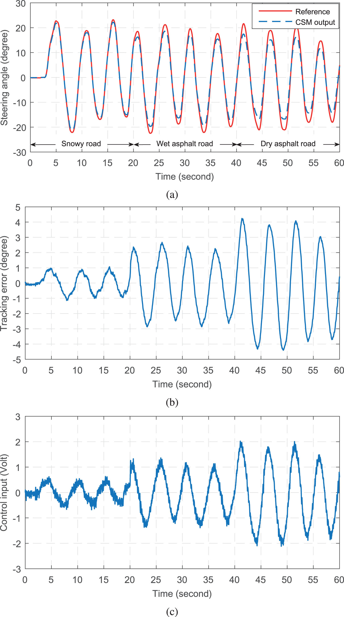
Control performance of the CSM controller: (a) Tracking profile, (b) Tracking error, (c) Control input.
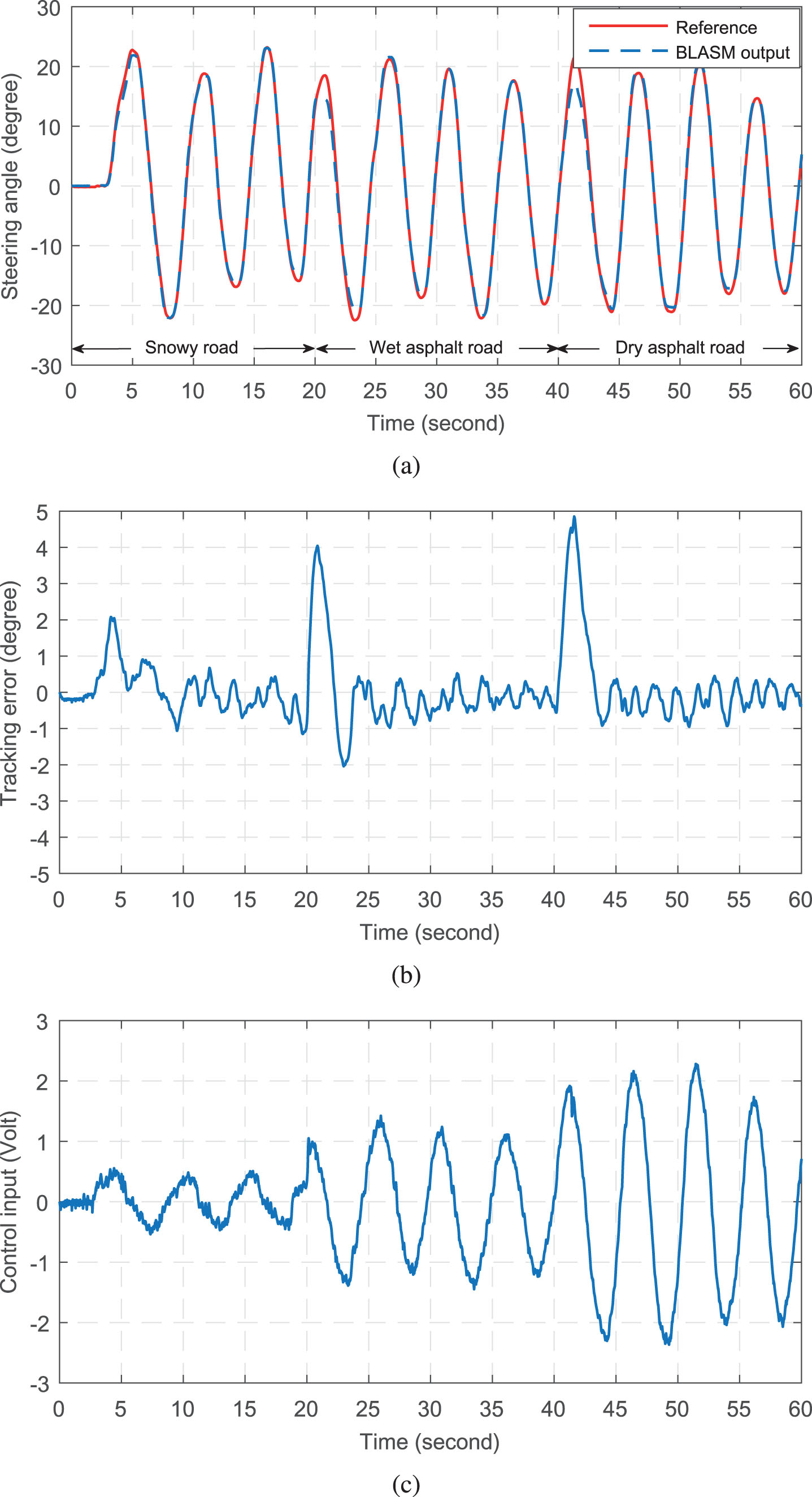
Control performance of the BLASM controller: (a) Tracking profile, (b) Tracking error, (c) Control input.

Control performance of the AFSM controller: (a) Tracking profile, (b) Tracking error, (c) Control input.
From Fig. 4 we can see that with the increasing of the main external disturbance, i.e., the self-aligning torque, the tracking precision of the CSM control deteriorates to a large extent. However, the tracking errors of the AFSM and BLASM controllers can converge to a small region of -1 to 1 degree regardless of the change of road conditions as shown in Figs. 5 and 6. This is due to the adaptive estimation of the Coulomb friction F c and the self-aligning torque τ. With an accurate estimation, a specific feedforward control component is then used to compensate for the effect of F c and τ, which leads to higher tracking accuracy and stronger robustness against various road conditions compared with the CSM control. We should also note that, at the beginning of each period of different road conditions, the peak tracking errors of the AFSM and BLASM controllers are slightly bigger than those of the CSM controller. This is because that the adaptation law requires a small period to learn the property of the disturbances. However, after the process of learning, the tracking errors can converge fast and obviously.
We can also see that there exists more chattering in the control input of the CSM controller compared with the other two controllers. This is because that the upper bound information of the self-aligning torque
From Figs. 5 and 6 we can see that both the proposed fuzzy scheme and the conventional boundary layer technique can alleviate the chattering phenomenon. However, if we adjust the AFSM and BLASM control with approximately the same level of chattering, not only the peak errors but also the RMS errors of the AFSM control are smaller than those of the BLASM control in three periods, which is clearly shown in Table 1. This is because that the boundary layer technique is based on a linear function with respect to the switching variable inside the boundary layer, which is conservative and weakens the tracking accuracy. However, the proposed fuzzy scheme is more intelligent in dealing with chattering and can strike a better balance between the control precision and smoothness.
Tracking errors
Figure 7 shows the bar charts of the peak errors and RMS errors under three controllers in different road conditions. From Fig. 7(a) we can see that the peak errors under the CSM control are slightly smaller than those of the other two controllers. Because the adaptive-based controllers require a small period to learn the property of system dynamics. However, as shown in Fig. 7(b), the RMS errors of the CSM controller under the conditions of a wet asphalt road and a dry asphalt road are much larger than those of the other controllers. Thus, the control performance of the BLASM and AFSM controllers are superior to that of the CSM controller. From Fig. 7 we can also see that regardless of the variation of road conditions, all the peak errors and RMS errors of the AFSM controller are smaller than those of the BLASM controller. Therefore, the proposed AFSM control demonstrates the best control performance comprehensively among the three control schemes.
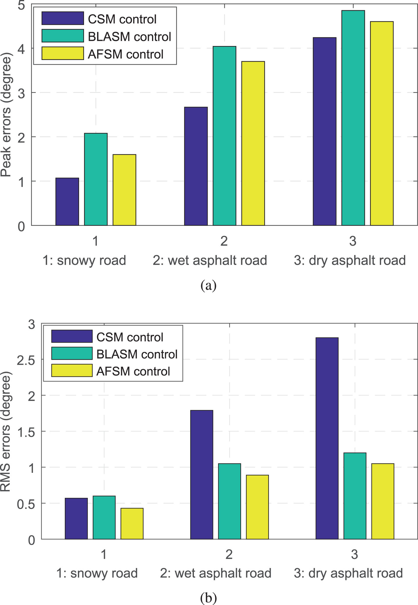
Bar chart of tracking errors under three controllers: (a) Peak errors, (b) RMS errors.
In this paper, an AFSM control scheme is developed for vehicle SbW systems, which integrates the merits of strong robustness against system uncertainties brought by a sliding mode control component, high tracking accuracy brought by an adaptive estimation of external disturbances, and a satisfactory balance between the control precision and smoothness brought by a novel fuzzy strategy. The stability of the closed-loop control system is verified in the sense of Lyapunov, and the guidelines for selecting control parameters are elaborated in detail. Finally, experimental results are shown and analyzed, which demonstrates the superiority of the AFSM controller in comparison with the CSM controller and the BLASM controller.
It should be noted that the self-aligning torques acting on the front wheels are simulated but not real ones in experiments. The experimental setup cannot completely match the real scenario at current stage. However, our combination of the sliding mode, adaptive and fuzzy control and experimental validation are still beneficial for industrial references. Our future work is to upgrade our experimental setup into a real SbW-equipped vehicle that is able to run on the road. Furthermore, we can expand our research into more cutting-edge directions such as SbW-based driverless vehicles.