



Abstract
The autonomous navigation problem is currently a popular research topic encountered in many different areas, from smart cars to automated warehouse operations. Autonomous navigation of robotic systems is examined in two basic areas, with and without external supports. Even if the robot uses external supports (like GPS, road signs, ground surface lines, barcodes etc.) or positioning itself with internal sensors (like gyro, IMU, etc.), it independently needs a control method to follow the desired route. When the widely used control approaches in the literature are examined, PID and fuzzy-based approaches are frequently encountered. They both offer advantages and disadvantages. Within the scope of this study, the positive aspects of both of control approaches are utilized and the hybrid control approach for a robot that can autonomously follow the ground line presented as an external reference is mentioned. The success of the approach was tested comparatively on an exemplary mobile platform. The applied results obtained experimentally showed that a more efficient fuzzy logic-based hybrid control method could be developed. In addition, the effect of the number of conditions in the rule table on the success of the hybrid control technique is shown in the study. It has also been experimentally demonstrated that the success of hybrid control approach with a limited low power consuming ARM based processor that is suitable to control most of lightweight mobile platforms.
Introduction
One of the research topics that has been widely studied for mobile robots is undoubtedly the autonomous navigation problem [1]. The researches carried out in this field has a wide range of applications from driverless vehicles [2, 3] to autonomous material management in a storage area [1]. The main concept of an autonomous robot is to complete tasks such as navigation, avoiding obstacles, achieving the goal without human intervention. One of the popular examples of autonomous self-navigation mobile robots is line followers [4]. Their simple design allows them to be seen as the appropriate infrastructure for the rapid autonomous implementation of very complex tasks like Amazon warehouse inventory management system [5].
The first stage of performing the autonomous navigation task is detection of robot position in its environment. For this purpose, two basic approaches are used in literature, based on external references [6] and calculated with robots’ internal sensors [7]. The positioning approach realized by making use of external references can produce more precise and long-term reliable results. Therefore, if the usage of external reference is possible, they are preferred more. Satellite based global positioning systems (like GPS, Galileo, GLONASS etc.) are seen as widely available approaches, but different signs and mark detection methods are used especially indoor environments when the access of satellites is not possible. However, in this case, detection or perception of external references by the mobile robot is another problem. There are various methods and sensors that are used to detect the line or markings on the ground surface or around the robot. The path may be a visible black line on white surface, or white line on black surface or different marks like barcodes or QR-codes. Sensors can be different types and they may have different features; for example, infra-red (IR) line sensors can be used as sensor array [8] or an optical camera can be used [9, 10] to get a grayscale real-time environment video.
The second step is autonomous control of mobile robots considering the sensor data. Keeping the robot in the desired path is another part of autonomous navigation. Line followers with their simple designs and low-cost solutions are robots commonly used for this purpose and there are various studies about control of Line Follower Robots (LFRs) in the literature [11, 12]. They are the basis for complex control structures such as smart cars’ line keeping systems [13]. A fuzzy controller for the LFR with distance keeping approach has been designed and developed in [14] as another example.
LFRs provide some conveniences like following the desired route but also there are some difficulties and issues to be solved in the control of the line-following robots. Although they provide the ease of determining the route, the approach also brings some obligations such as traveling without leaving the sight of line or marks. Therefore, a special control approach is needed that allows displacement of the mobile robot without leaving the line or sight of marks. Particularly during the sharp turns or narrow angle maneuvers, especially while travelling with limited speed, keeping the line or marks in desired position is an important control problem. The mobile robot can easily get off the track and it may lose the line or marks. Lowering the robot’s speed can be a method for solving some problems but it’s not easy to determine the optimum speed of each motor especially while using differential steering mobile robot [15]. An important limit to be addressed for mobile robots is power consumption. The usage time of the mobile robot is directly related to energy consumption. Therefore, it is important that it consists of low power components to achieve longer usage times. In addition, carrying less battery will allow the platform to be lighter and have motor systems that require less power, thus providing longer service times with less battery power. However, this will cause the entire control system to be implemented with low power and light processors.
This study focused on combining two popular control methods; proportional integrative derivative (PID) and fuzzy as an efficient hybrid solution to control the LFR autonomously. In order to demonstrate the success of the hybrid approach, proportional derivative (PD) based control, which is a kind of PID control approach, then fuzzy logic-based control and finally the success of the hybrid approach has been experimentally tested in this work. The effectiveness of control approaches is discussed.
In this paper, an Arduino based LFR is designed. The performance of control approaches on the low power consumption processor has been tested comparatively. Furthermore, by considering low process power, different versions of the hybrid control techniques suggested and compared. An IR light sensor array is used as detection sensor to track the ground surface line. Even though an IR light sensor is used in this work, defined control methods are kind of adaptable solutions and they also can be used with different sensors.
Related researches in the literature is detailed in the chapter 2. Basic information about PD, fuzzy and hybrid control approaches are given in chapter 3. The components of the test robot, software architectures and the real-time test setup are detailed in chapter 4. The experimental results and discussion about results are placed in the next section. The results are given in the last part of the article.
Related work
Line follower robot control is an interesting research field for many researchers. Different controllers have been used by many researchers for LFRs. The most common control techniques in the literature are PID and Fuzzy based controllers.
A PID based control algorithm has been developed by Gomes et al. [12] for a unicycle type automated guided vehicle to follow a line while avoiding oscillation on its movements with optical camera as a sensor to give feedback information. Considering a simplified model and a classic PID based control technique, the stability has been obtained on lower speeds. Traditional control system theory is effective and sufficient for systems that can be modeled with mathematical equations [13]. However, these control approaches are insufficient in the use of systems that are too complex to be accurately and precisely defined by mathematical models.
In [16], Ismail et al. explain their technique in fuzzification of an array of digital sensors with an application to a LFR and then successfully apply fuzzy logic control system to the developed mobile robot and present the results for the LFR motion control yield in much faster and efficient tracking comparable to PID and switching algorithm that uses the same platform. This is a similar approach with the technique that is planned to use in this work. But Ismail et al. used a selection mechanism to change the control technique one to another which is much successful during motion instead of combining them as described in this paper like a hybrid approach.
Some applications need to use multiple controllers together in a robot. As an example, in [17], Binugroho et al. proposed to use multiple PID control algorithms as a cascaded architecture for a line follower and balancing robot. The robot must balance itself while it is following the trajectory at desired speed. So, the authors suggested to use three controllers together as defined as balancing, speed and line following controllers. All of three controllers are cascaded and all of them give commands to same two motors as robots actuators.
In the following chapter detailed information about control approaches are given with the advantages and disadvantages of each one.
Controller design
In this chapter of work, PD, Fuzzy and hybrid control techniques are detailed orderly.
PD controller
A PID controller has proportional, integral and derivative control modes. These modes react differently to the error, and the level or degree of control can be adjusted individually for each mode. Proportional control mode changes the controller output proportional to the error. The parametric value is gain (K
C
). This can sometimes be defined as the P setting or proportional setting. The control action is proportional to the controller gain and error. A high gain value will increase the exit action and increase the error as well. Using proportional control alone causes a large offset. Offset proportional control is a permanent error that cannot be eliminated by itself. When only proportional control is used, the offset (fixed error) value cannot be removed until the operator gives a certain bias (fixed additional value) value to the output. The integral mode (I) of the controller performs correction by continuously reducing and increasing the controller output to reset the error or offset. After a certain period of time, the integral mode resets the error. If the error is high, the integral mode makes the reduction and increase in the controller output faster, if the error is small, the changes are slower. The third controller mode in a PID controller is derivative (D) mode. Derivative control is used less frequently in process control than others, it is generally used in motion control. The process is not required for control and is very affected by the noise generated in the measurement and may not work properly. In addition, using derivative mode makes the controller more sensitive and accelerated than PI mode. The derivative control mode is also defined as rate. If the derivative mode error change is fast, it will affect more, if there is no change in the error, it will not do anything. Proportional, integral, derivative controllers are defined as PID controllers and all three control modes are used together as seen from Eq. (1). Finding the appropriate parameter settings for PID modes (K
P
, K
I
, K
D
) is a serious experience.
The effects of coefficient parameters for PID control are summarized in Table 1. K P is used to decrease rise time, K I is used to eliminate the steady-state error and K D is used to reduce the overshoot and settling time. The coefficient parameters must be set correctly, to obtain that the system works properly.
The effects of increasing PID parameters
Within the scope of this study, it was decided to use the PD control approach, which is a form of the PID controller, to provide LFR control, for reasons such as stability, simplicity and operating speed. First of all, for the PD controller, the KP parameter value that determines the system response error must be determined. If this value is too high, the error is compensated but passes the equilibrium point. The error change is calculated to reduce the effect of the error that also determines the K D coefficient.
There are different approaches to determine the correct coefficient parameters for PID controller in the literature. These approaches are like analytical, empirical, trial and error. Applying the analytical method is the hardest one but they are the best method to define the physics of the system. Also, there are some different techniques like Ziegler & Nichols, manual tuning (experimental), etc. [18].
The proportional sensitivity, integral and derivative time can be calculated using Ziegler & Nichols tuning formula [18]. Zeigler & Nichols described simple mathematical procedures for tuning PID controllers. The S-Shape response, which is shown in Fig. 1, can be defined by a tangent line at the inflection point of the curve and two parameters, L delay time and T time constant which are determined by their intersections with time axis and steady state value. Ziegler and Nichols derived the control parameters based on model which is shown in (2). In process control systems, most of plants can be modeled by Eq. (2).

Illustration of S-Shape response.
However, Ziegler and Nichols method is a kind of solution to determine the coefficients for PD controller, it is hard to implement in most models. Instead of calculating K P and K D values with Ziegler and Nichols method, usually they are calculating with experimental approaches. System parameters vary depending on the changing factors (speed, light, path changes, etc.) for LFR. Due to the change of these parameters, the K P and K D values of the PD controller must be changed appropriately to prevent the system control from changing. There is not any absolute set of values which can be applied to every system, so the selection of parameters depends on the physical characteristics of the system. The success of PD controller is really satisfied when the coefficients are determined correctly. But it is the hardest part of the process, and usually it is not possible to find the perfect K P and K D values for the LFR’s control.
Fuzzy controller is a control method based on fuzzy logic, which can be described as “control with sentences rather than equations” [19]. Fuzzy logic controller (FLC) can be easily applied to control nonlinear systems without an exact mathematical model of plant. Flow chart of FLC is shown in Fig. 2. The basic FLC has four components; The first one is Fuzzification component, involves measuring the values of input variables and creates a scale map that transfers the value range of the input signals to the corresponding discourse universes. Second one is Knowledge base also known as rule-base, includes a database and a linguistics control. This database has definitions of linguistic control rules. Decision-making component simulates human decision-making based on fuzzy concepts. Last component is Defuzzification like fuzzification, makes a scale mapping, it converts the range of values of output signals into corresponding universes of discourse which performs a non-fuzzy control action.
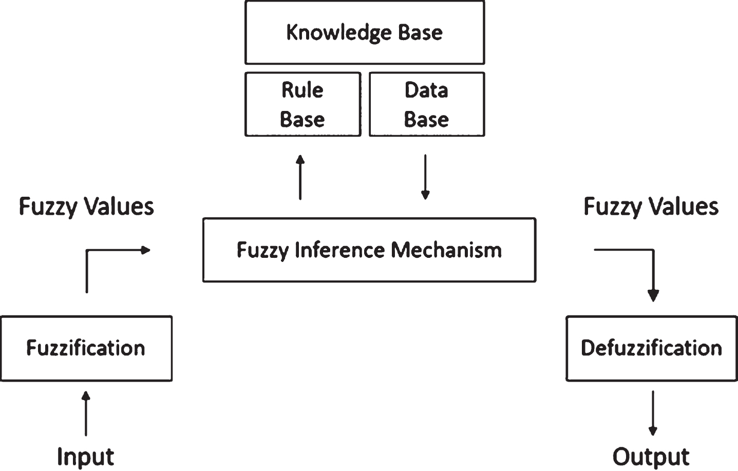
FLC flow chart.
The control structure of PID controller can be easily interfered. So, it offers a changeable control approach and it has an easy programmable structure. However, this structure needs an excellent mathematical model for the system solution otherwise K P , K I , K D parameters are difficult to determine. Unlike the PID controller, fuzzy logic controllers need simple mathematical model to create a controller structure. But this method has implementation and programming difficulties instead of PID controller. It is difficult to build fuzzification – defuzzification membership functions and it needs to create complex rule base for perfect control modeling. When the FLC approach is evaluated in terms of the control of the LFR, the application difficulty is encountered with high processor need and defining membership functions.
Adaptive Fuzzy PD (fuzzy proportional derivative) controller is a hybrid control strategy based on fuzzy rules, achieved by the combination of two described control approaches. It aims to combine the advantages of the previous two approaches. It affects the same input signals as the PD control. The controller has two input signals: error and change of error. These two inputs are processed by the rule base stage to produce a new fuzzy variable.
The flow chart in Fig. 3 represents the operation steps of the hybrid controller. As seen from figure, initially experimentally determined values of K P and K D are assigned to the system. Then the error of the system is measured with the sensor. The PD controller determines what the motor speeds of the LFR should be. The robot moves according to these control output values. With sensor measurement again, the error is updated and fuzzy controllers recalculate the values of K P and K D for PD control depending on the rate of error and error value. At this point, a hybrid control starts to run as a close loop control approach.
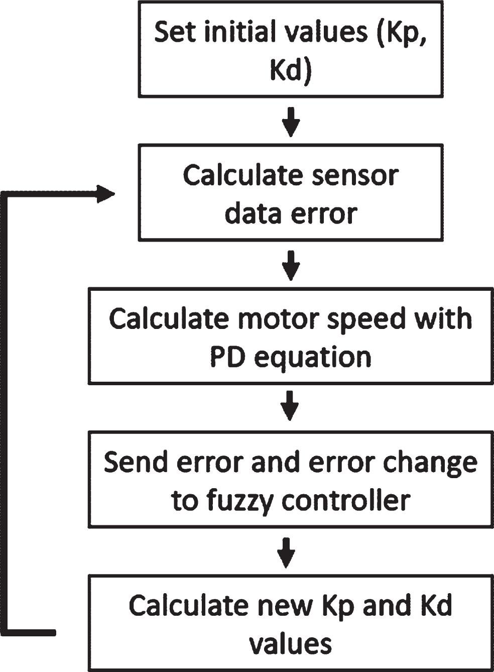
Flow chart of model controller.
Single fuzzy logic controller is used with two outputs, first of them is dynamic KP value and the other one is dynamic K D value. The system configuration is shown in Fig. 4.

Fuzzy based hybrid controller design for LFR.
The biggest advantage of Adaptive PD Controller is dynamically determining control parameters. Thus, it was possible to adapt to the situations arising from both the control architecture and external variables affecting the sensor. In addition, execution of maneuvers with different characteristics for LFRs will require dynamically adaptable PD coefficients. Undoubtedly, the expectation will be that the robot’s reactions to different road line curves will be much more successful. At this point, the factor affecting the success of the hybrid approach will be the number of rules in the rule base of the fuzzy controllers. Increasing the number of fuzzy controllers will cause performance problems on low power processors. To prevent performance bottlenecks, the most effective solution should be aimed with the minimum number of rules. So, the number of rules for fuzzy controllers are limited to 9 and 25 in this study. The main objective of using two different rule set, demonstrate the effect of number of rules on the success of line following process. Usage of the number of rules is very limited by considering the mobile processors with low power consumption. By considering performance of the processors, different rule sets can be used.
In this part of the work design of the LFR, definition of test track and developed hybrid control approach is described.
Design of line follower test robot and track
Test robot that is used to evaluate the performance of the different control approaches in this work, can be seen from Fig. 5.

Side view of designed LFR for test.
The chassis of the LFR is designed distinctively and manufactured with 3D printer as a durable and lightweight part. Reflectance sensor array is used to detect the line on the track. IR light sensor is chosen due to cheap, popular and easy modelling. Sensor reads the reflectance by withdrawing the externally supplied voltage and timing how long it takes the output voltage to decay due to the integrated phototransistor [20]. There are two free spinning balls as front wheels of LFR. Besides, by using rear wheels and motors differential turn control is implemented benefiting from different turn speeds and directions of rear wheels. Motor driver shield is used to drive the DC motors with controlling speed and direction. Lipo type battery is used to energize all robot. Arduino based microprocessor is used as brain to run real-time control algorithm and read the sensor values on the robot with limited energy consumption. Additionally, a bluetooth module is used to establish communication between robot and monitoring PC. A screen with touchpad is used to see and change configuration parameters on run-time.
The most important feature considered in the robot design and selection of its components has been determined to ensure that the LFR moves at the highest speed that can go without leaving the line on the ground surface. Therefore, light and low power components are selected. In addition, a programmable processor with sufficient memory space has been chosen in which the different algorithm approaches can be realized by programming. The LFR developed in this study has been presented as an exemplary platform and represents the typical characteristics of traditional LFR type mobile robots. For this reason, it incorporates the typical common features intended for all LFRs developed for different purposes such as speed, item handling, and material distribution. The main objective of this research is demonstrating the success of different type of control methods experimentally for the LFRs.
For this reason, in addition to the LFR design, a runway definition has been developed that includes components that will push the limits of the developed control algorithms of the mobile robot. All control approaches described in this work were tested on the same test robot and on the same track under the equal conditions, so the performance comparison of control methodology was carried out experimentally. As seen in Fig. 6, different wide/narrow radius or sharp/soft turns, straight paths enough to accelerate and ground lines with variable colors are exist in the track.
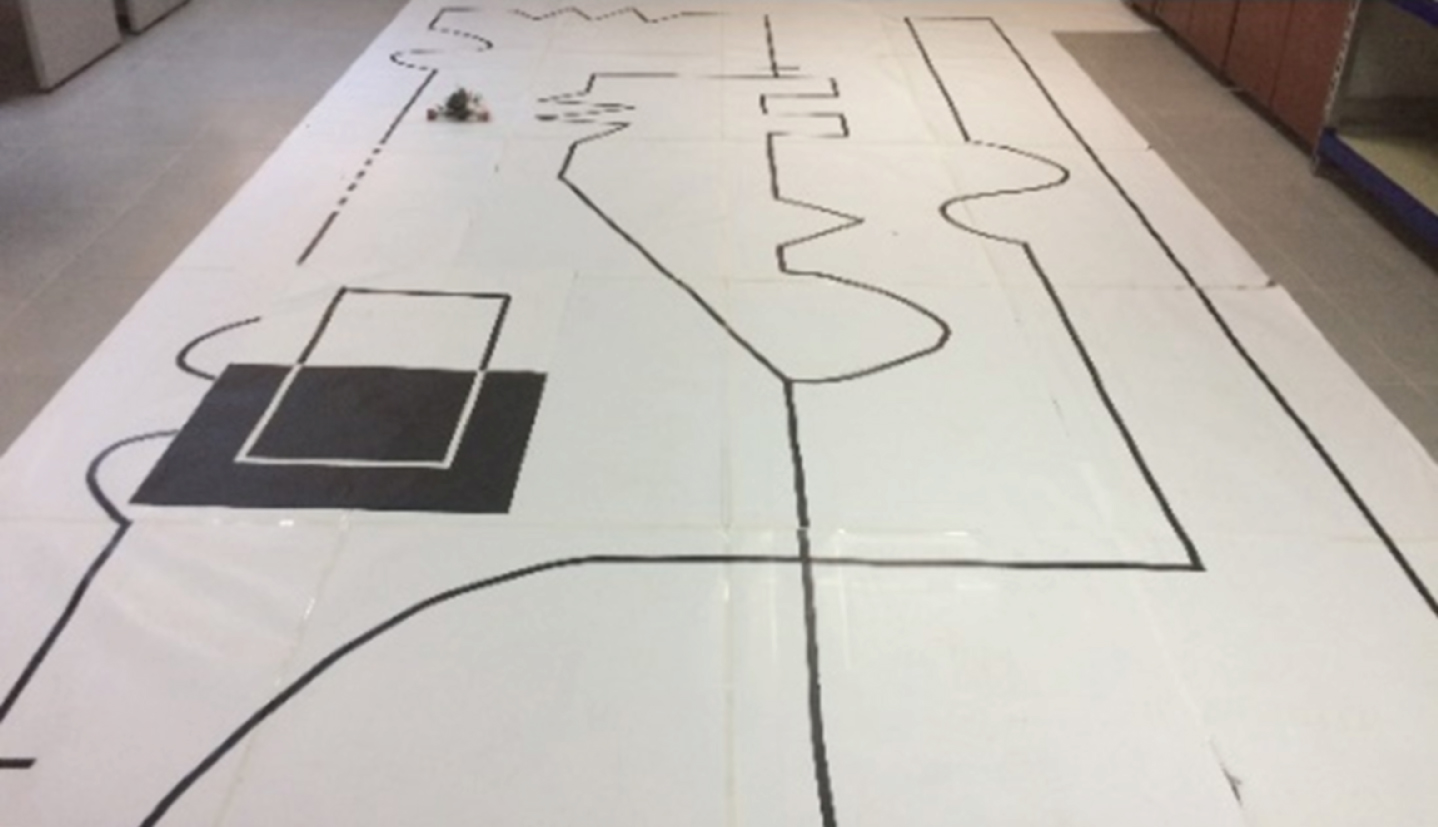
Test path for the LFR.
In this study, PD controller was applied on LFR to compare the success of different control approaches experimentally. For the use of the PD controller, it is necessary to determine the effective KP and KD values as described in the previous section. These values have been determined experimentally by trial runs depending on the vehicle and track features. Effective values were determined as 0.1 for KP and 4.0 for KD experimentally. The vehicle has succeeded in following the line by using the PD controller with the fixed values and successfully completed the entire track, just a few times leaving from the line. The hybrid control approach can be adapted by tuning the parameters dynamically that affect the performance of the controller. This ensures that different control parameters are calculated and used instantly for the different track conditions such as sharp or soft turn or environment conditions that effects the performance of sensor like light.
In addition, two different hybrid control approa-ches with different number of rules were developed and compared to show the relation between controller success and number of rules in rule table of controller. In the first configuration there are three different membership functions for input and output signals, and each controller has its own rule table. Rows and columns represent membership function equivalents of error and error change values, while each cell value in table shows the output value membership function value. Totally nine rules are defined and used as shown in Table 2.
Rule table with totally nine rules
Rule table with totally nine rules
In the second configuration there are five different membership functions for input and output signals and totally 25 rules are defined on rule tables as shown in Table 3.
Rule table with totally 25 rules
Acronyms in Tables 2 and 3 are the linguistic variables that are used to represent the ranges of input and output signals of fuzzy controllers like Negative Big (NB), Negative Small (NS), Zero (ZE), Positive Small (PS) and Positive Big (PB). Membership functions represent the characterization of fuzziness whether the elements are discrete or continuous. Membership functions are represented by graphical forms and they may be in different shapes like Triangular, Trapezoidal, Gaussian etc. The membership function of fuzzy controller Kp inputs and output can be seen from Fig. 7. Similar membership function’s forms are also used for Kd fuzzy controller inputs and output. Another point is to reveal the relationship between processor power and the number of rules used in the control approach. Two different hybrid control methods were developed on two different processors (Arduino Uno with 16Mhz ATmega328 2KB SRAM, 32KB flash and Arduino Mega 16 MHz ATmega2560 8KB SRAM, 256KB flash) to see the effect of the number of rules on processor performance. The Arduino Uno microprocessor that is used on the test LFR causes a loss of performance when more than 9 rules are used. Because of the limited computation power of Arduino Uno microprocessor, the number of rules is reduced, only nine rules are used. To developed more efficient hybrid controller with 25 rules Arduino Mega processor is used.
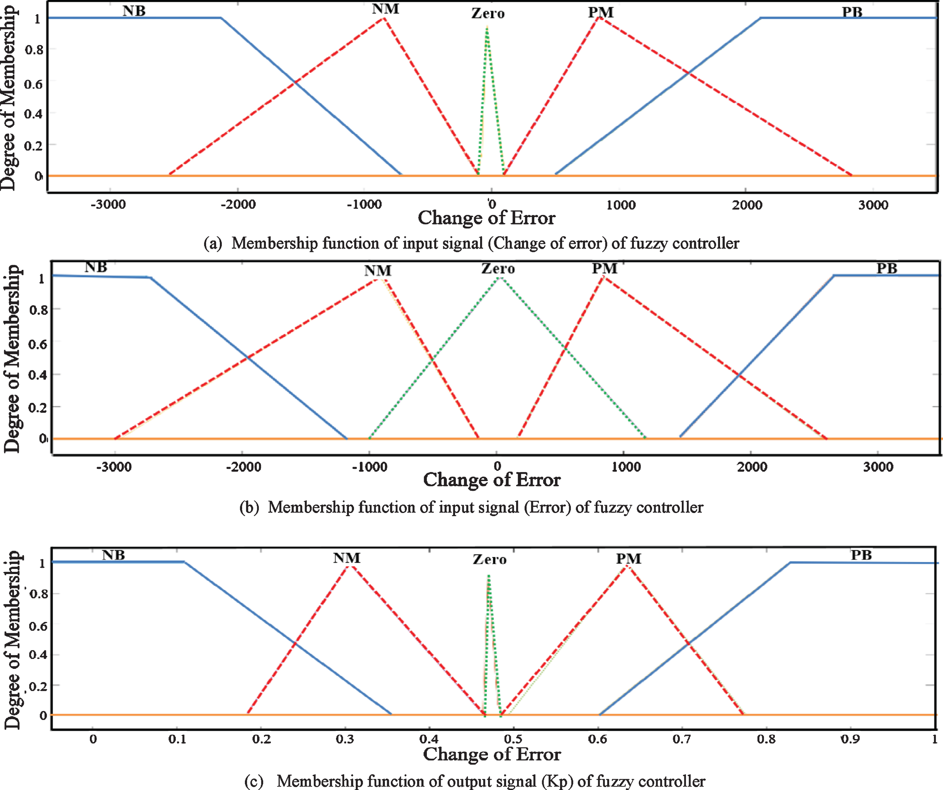
Membership functions of inputs and output.
The created surfaces with these rules can be seen from Fig. 8. It is important that the surface must be smooth as much as it can be in an efficient fuzzy controller. Smoothness of the surface indicates that there are no sudden changes. We can smooth the surface by adjusting the number of rules and the range of membership functions. The surface for the first configuration is not so smooth because three member functions are used for i/o signals as seen from Fig. 8(a), if the number of member functions are increased as seen from Fig. 8(b) as second configuration that makes the output smoother.
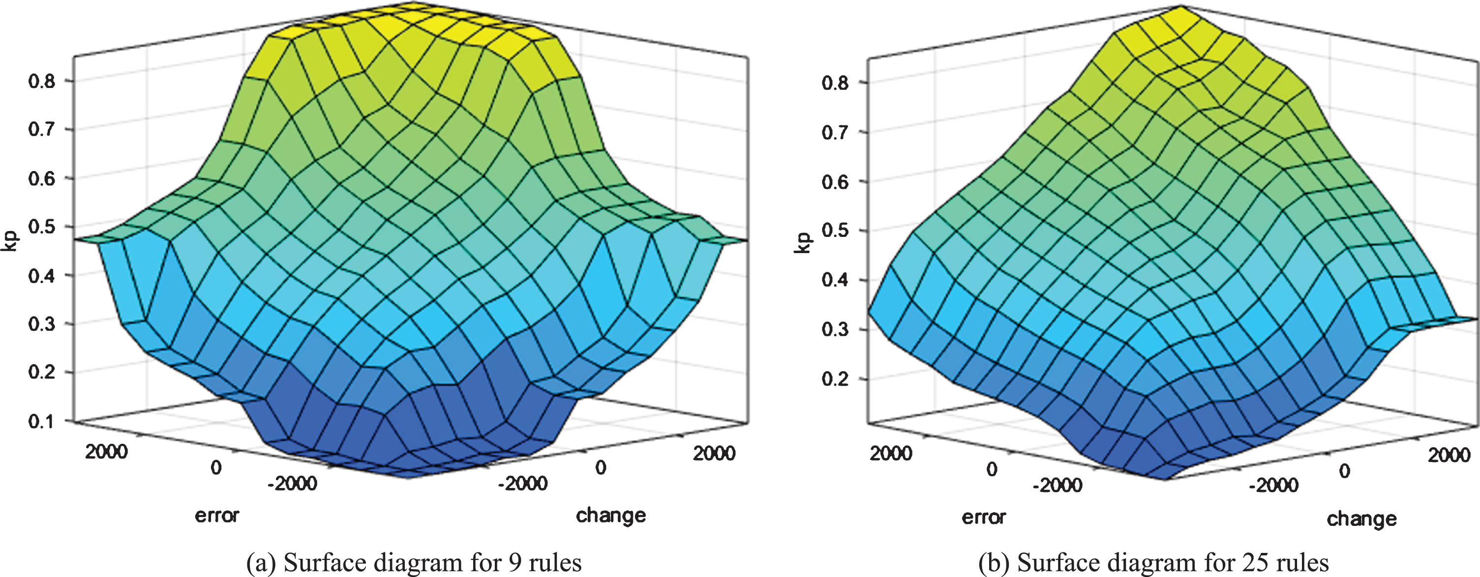
View of the surface diagrams.
For the LFR defined in the previous section, three control approaches defined in order to perform the movement of the mobile robot without leaving the line on the ground surface were performed on the test pattern that is also defined in the previous section. First of all, the control of the mobile robot was carried out with the PD controller, then it was carried out with a hybrid fuzzy logic-based control approach with 9 rules and 25 rules orderly.
LFR has totally eight IR emitter and receiver pairs as sensor array. If the robot moves smoothly on the line, only 3rd and 4th sensors have readings, and it means that mobile robot is centered on the black line. If the vehicle moves on center of line, the position values are expected to be between 3000– 4000. On a straight line, if the sensors except the third and fourth one read black ground surface color value, it means that they are producing errors and the mobile robot is not on the center of the line. Values outside the range of 3000– 4000 refers to the error.
Comparison of controllers
Comparison of controllers
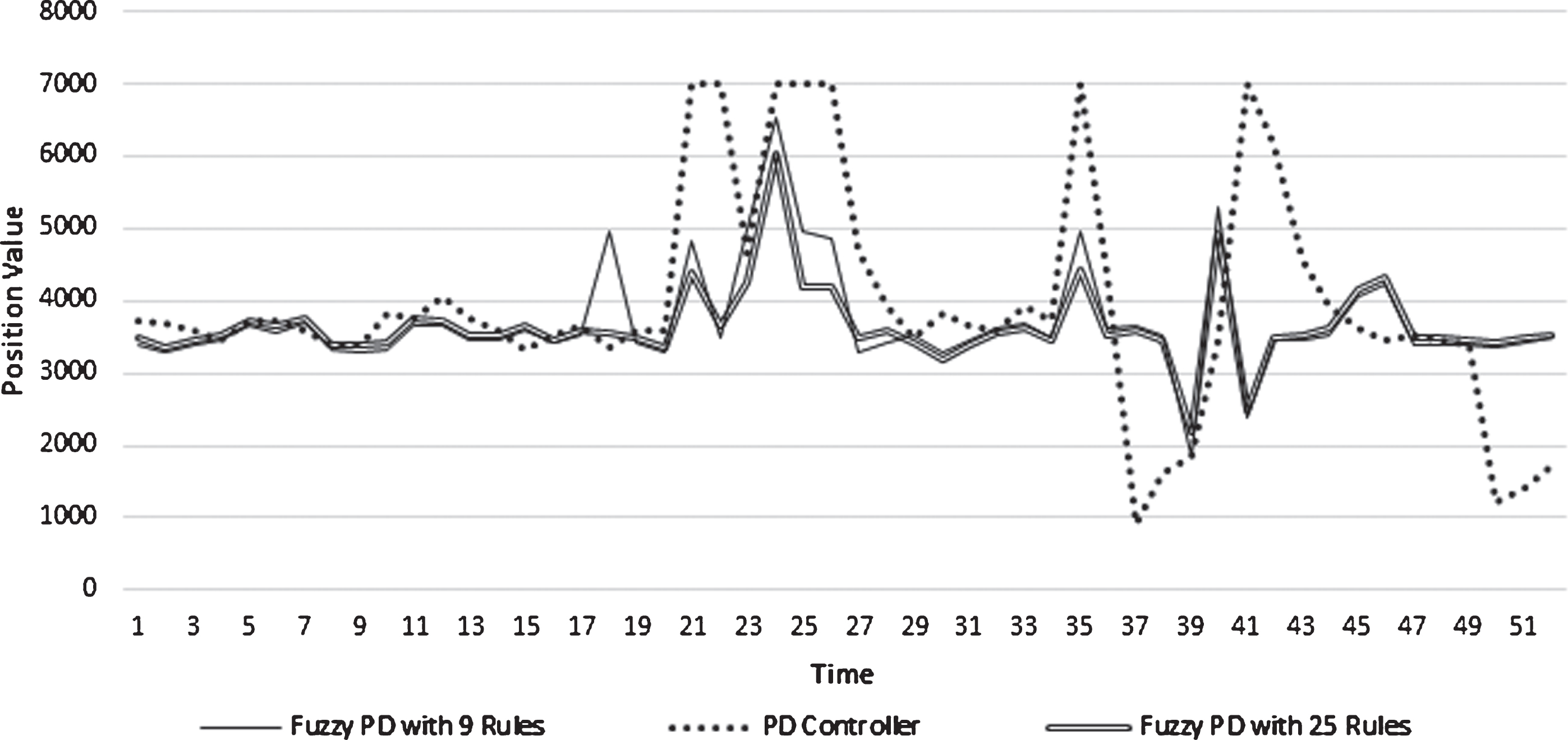
Position error sensor values obtained by different LFR control methods.
An application has been developed with the MATLAB programming language to store the data in a series, graphically show the line tracking success and interpret the success of different control approaches.
As seen from Fig. 6, different type of test patterns has been evaluated with robot. Each type of the line during the path is numbered differently on Table 4, like straight road, concave bend, convex bend, sharp bend and zigzag as line number 1 to 5.
LFR cannot move continuously by centering the line on the ground surface. The sensor array on the mobile robot will read error values as long as the LFR cannot center the line. In each transfer of sensor value, if the transferred value is outside the average range of the line, a counter value will be increased as a counter, which means that the vehicle is in undesired position. Thus, the number of times the sensor sends the value of the vehicle in the wrong position, counter values will be increment and by using this value control approaches can be compared as seen from Table 4. It can be seen from Table 4 that the PD controller has reached the maximum error value in each different test line type determined on the path. In addition, hybrid controllers have managed to perform relatively successful line tracking. This is achieved by dynamically changing PD coefficients with fuzzy controller. In addition, by examining the data in table, it is seen that how different number of rules affect the success of the hybrid controller. As seen from the values in Table 4, as the number of rules in the fuzzy rule table of the hybrid controller increases, the success of the control increases.
Figure 9 shows the position errors produced by the LFR, which moves with PD, 9-rule and 25-rule fuzzy logic-based hybrid control approaches. As seen from the graph, the test robot, which proceeds with all three control approaches, has been separated from the line at some points during the test. However, it is clear that the approach that makes the most mistakes is PD and the reason for this is the use of fixed control values. The fuzzy logic-based control approach, created with more rules, completed the pattern as the most successful control approach. The reason for this success is that the adaptive control parameters are determined with conventional logic controllers and used according to changing conditions.
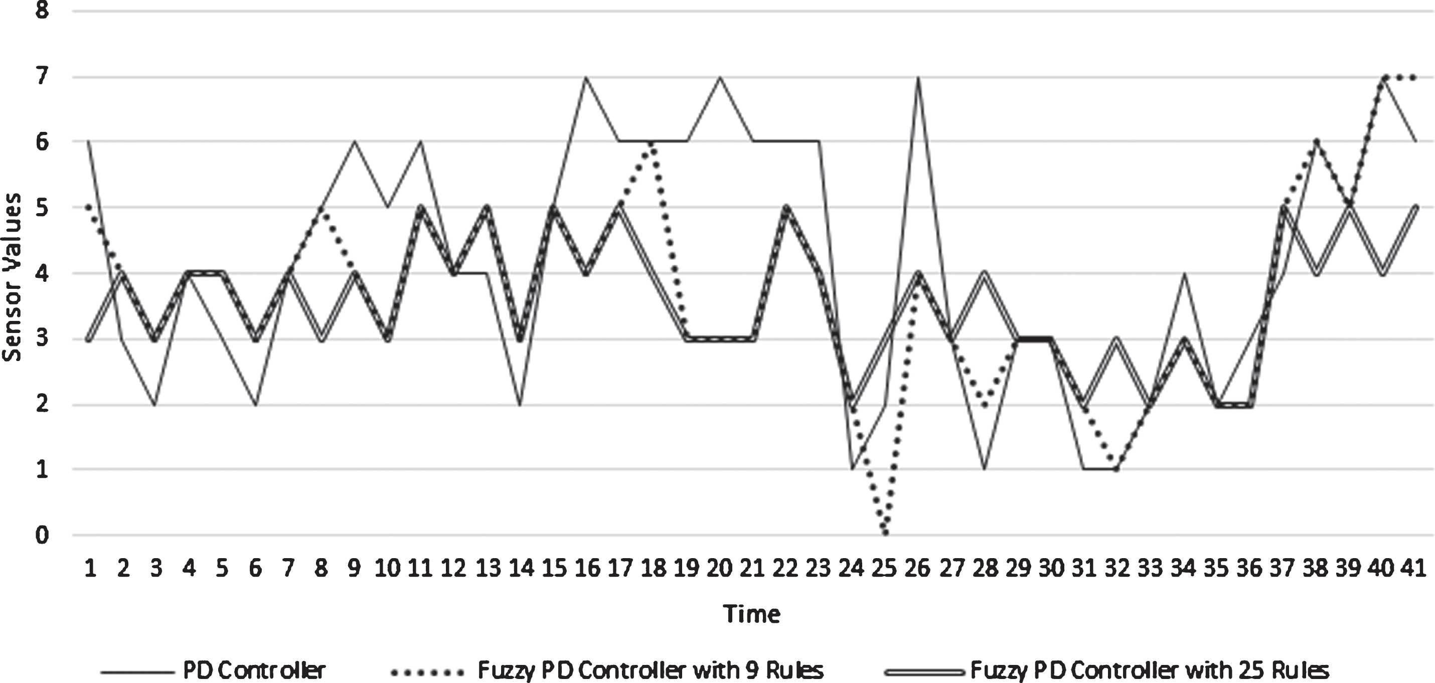
Sensor values of robot obtained by different LFR control methods.
In Fig. 10, it is seen which sensor in the sensor array reads the value while following the line by using different control methods. As long as the robot following the line on the ground surface as centered, the sensors that read the value are expected to be sensors 3rd and 4th. However, this situation varies during maneuvers, such as sharp turns. How long the robot continues its movement by staying centered to the line is shown by the fact that the line is quickly readable with sensors 3rd and 4th again. When Fig. 10 is examined, it is seen that the fastest reaction time and the most successful and effective control approach are realized by the fuzzy logic-based hybrid controller with 25 rules.
In this study, an adaptive hybrid controller is designed and developed for the control of autonomous LFRs. The coefficients of PD controller can be updated instantly by using fuzzy controllers. So, the robot can follow the line without left it as much as possible. The main reason why the hybrid approach is more successful is that it is an adaptive control approach that can autonomously adapt to changing environmental conditions.
The results obtained from the experimental studies on the differential steering mobile robot, reveal that the developed hybrid control approach is more effective than classic control approaches like PID and FLC. It is also clear that developed adaptive hybrid control approach can be applied to robots with different steering mechanisms and also similar results can be achieved. Another point that should be taken into consideration is that the control methods were all run on the energy-efficient processors with limited performance during the study. The success of the hybrid control approach depends on the number of rules in the fuzzy rule base, also this is the most important constraint that requires more processor performance. So that, the number of rules should be optimized in the hybrid control approach considering the robot mechanics, the route to be followed and the navigation method. By using processors with different performance values and different number of rules, the results were experimentally presented and it was provided to give an idea for similar studies to be developed. As a result, the main constraints that limit the hybrid control approach are rule count in fuzzy rule table and energy efficient mobile microprocessor performance.
In this study, reflectance sensor array is used to detect and follow the line. Different hardware such as camera can also be used with little modifications on suggested hybrid control approach. By using image processing techniques, video or image data can be processed instantly to detect the line, a combination of different types of hardware will reduce the error. However, this will increase the size and weight of the robot.
As a result, it has been experimentally demonstrated successfully in this study that developed hybrid autonomous adaptive fuzzy logic based control approach regardless of the physical properties of the robots and techniques used for positioning, which can be used with processors with low processing capacity and energy efficient, produced successful results when it is compared to classical control approaches. The proposed control approach can also be adapted for mobile robots with different types of guidance and sensor (positioning) systems with limited energy efficient mobile processors.
As a future study, the proposed fuzzy-based adaptive hybrid control approach can be applied to more complex autonomous platforms such as unmanned aerial and marine systems under the influence of a more dynamic and unpredictable environment.