
Abstract
In an Electrical system, Power Quality (PQ) is becoming significant to all types of consumers. With the increase of power demand from end users, maintaining the quality of power within the limitations is a major problem. In this paper, harmonic analysis in a grid connected three phase induction motor is tested according to PQ international standards which are found in the International Electro technical Commission (IEC). These mentioned standards are maintained in the transmission line and fed to the induction motor through a regenerative grid simulator. With the results obtained, execution of this fuzzy control system can be investigated through the digital simulation, which is based on MATLAB-SIMULINK package. It provides human operands to constitute a knowledge base which is used for diagnosing power quality and capable of predicting abnormal operation in Industries.
Introduction
Power quality (PQ) has become a point of discussion for the past couple of decades, and has lately strengthened its interest in more number of industrial processes which are very complicated [1].
In Many commercial and Business systems, computer networks is one of the key contributors in analyzing the power quality. For investigation of the PQ problems, the level of expertise in engineering should be high not only in single area but many of the electrical power areas. For delivering the power with quality, proper analysis of PQ problems have to be achieved by knowing the cause for uncertainty in the power. IEC-Electromagnetic compatibility (EMC) is the capability of an appliances/system to operate adequately in its environment of electromagnetic, without offering unbearable electromagnetic disruptions to any other things in that environment [2].
There exist the several factors which are complex in analyzing the PQ problems, which are not only limited to the large scale of data available from power analyzers and discrete configurations of modernized power transmission and distribution systems [3].
Total Electricity consumption is 40% to 50% by the electric motors and it has been gradually increasing. Out of these, three phase induction motors are the utmost majorly used electrical motors in industries because of their reduction in cost, robust, simple in construction, more reliable and ease of maintenance. It consumes 70% of electric power for industrial loads running [4]. Once the power system suffers the pollution of harmonics, the operation characteristics of induction motors and transformers will be affected first. The study of the impacts of these components under harmonics voltage has recently drawn the attention of many researchers.
Harmonics are mostly combination of higher order and fundamental frequency components which can be evaluated by using Fourier Transform. Total Harmonic Distortion (THD) is most basic factor for Harmonic analysis which is commonly characterized in Percentage. Classification of harmonics in Supply voltage can be done in three categories: positive, negative and zero-sequence components. Rotation of magnetic fields is in the same direction with respect to fundamental component. In negative sequence, the rotation of magnetic fields is in opposite direction. In Zero sequence components, usable torque is not developed and they inject additional losses in Induction Motor. Tensional oscillations are produced in the motor with the interaction of sequence magnetic fields i.e., positive and negative, which produce vibrations leading to increase in the mechanical (frictional) losses and decrease in the life span of bearings, belts, gears, etc, of the induction motor [5].
Interharmonics in power system are in general caused by the two of the reasons. The first is prompt changes which are non-periodic in voltage and current waveforms caused under transient state in load. Other is modulation of current and voltage waveforms which are implemented for the purpose of control. Changes in magnitude of current or phase angle can also lead to the reactive components of the fundamental frequency and its harmonics at the frequencies of interharmonics. When the magnetic circuits of the induction motor get saturated, it creates the interharmonics in their stator and rotor slots which may also increase at the time of start-up. Loading of torque which is variable and asymmetry of motor can also cause the interharmonics [6].
Fuzzy Logic control (FLC) is a solitary booming method of control, which possesses the capability of adapting parameter variations, and doesn’t depend on finite mathematical model. This paper focuses on the sequence of FLC to simulate various power quality issues especially Harmonics and Interharmonics as per the IEC standards using MATLAB Simulink.
Harmonics and interharmonics classification
Non-linear loads are responsible for harmonics injection to the grid. These harmonics distort the voltage which is consequently affects the performance of the other loads; especially electric motors [7–9]. Generally, the three-phase non sinusoidal; distorted, voltage can be written as:
where
Vf-fundamental rms voltage,
h-harmonic order,
Vh- hth harmonic rms voltage,
ωs-fundamental voltage radian frequency and
θh-phase angle of hth harmonic voltage.
In General harmonics can be quantified using two factors. Those are harmonic voltage factor (HVF) and total harmonic distortion (THD).
Where h = 5,7,11,13,17,19,23, ... etc.
Ph- per unit magnitude of hth harmonic voltage to the fundamental voltage.
Magnitude (M) of any Interharmonic Group (IG) is given as
Magnitude of the Harmonic Group (HG) calculation consists of interharmonic components closest to the all harmonic frequency.
Magnitude of the Harmonic Subgroup (HSG) magnitude calculation includes only the harmonic frequency.
Harmonic distortion can be determined as the square root of sum of the squares of all individual harmonic components of significant value. Similarly, a total interharmonic distortion can be determined by considering the square of the sum of the square root of the sum of the squares of all interharmonic groups of significant value [10–13].
Regenerative grid simulator
As shown if Fig. 1, Regenerative grid simulator can be used to modify parameters which are significant in order to simulate reliable distribution grid/network situations and conditions. Variations in parameters which are sustained are voltage amplitude, frequency, voltage drops and phase angle in either single or three phase modes. Unbalanced conditions in three Phases can be simulated easily. This simulator is also adequate of meeting IEC regulatory standards’ 61000-3-2/-3-3/-3-1/-3-12 which is requirement for AC supply.
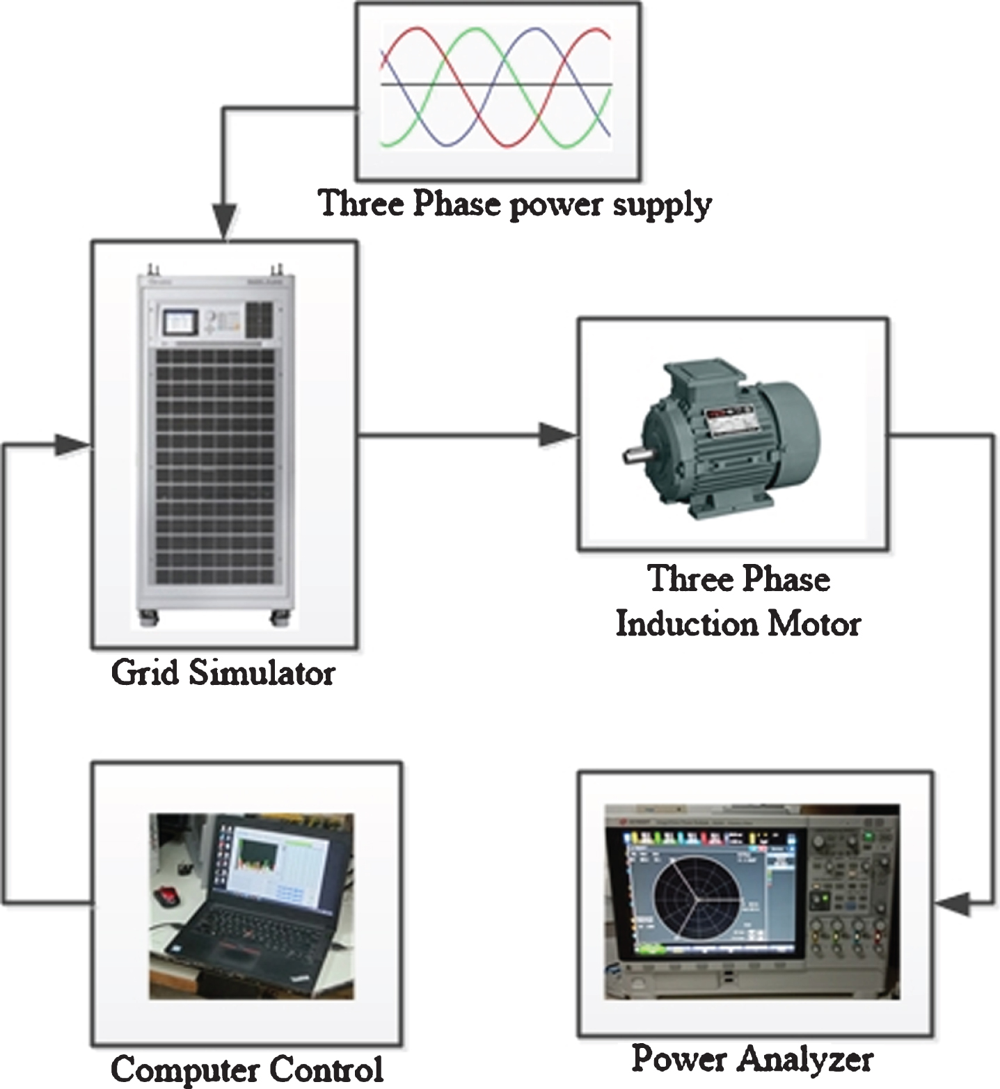
System configuration.
Graphical User Interface (GUI), which is explicitly designed to afford an easy way to interface for configuring the regenerative grid simulator. The Soft panel (GUI) is installed in a computer also equipped with recordings of data functions, which allows numerous measurements to be reported and saved simultaneously.
Load (induction motor)
For the Distribution network, 3 phase 1HP Induction motor is connected as a Load.
Power analyzer
Electronic power conversion structures should possess high accuracy measurements to analyse and describe incremental efficiency developments in devices. Earlier, power analyzer are used to make measurements accurately and to visualize repetitive an oscilloscope and specific shot events such as turn on and transients occurrences were used. A separate Oscilloscope was Eliminated in the measurement setup reduces complexity and configuration time.
Test process
At first, one out of four types (GPIB, RS232, USB, and LAN) i.e., USB is selected for communication interfaces between PC and AC source. When the communication protocol is set, it enters into the main window. The voltage & frequency Parameters and sinusoidal output waveform should be selected as desired. Phase edit selection can be done for controlling the output voltage in three phases for convenience. Different power quality tests as per the standards mentioned can be performed in the window displayed in the PC and the results are recorded through power analyzer.
Experimental tests & hardware results
Individual harmonic results
Individual Harmonics may define as the Continuous distortion of voltage and current waveforms from their original shape results in periodic phenomena of the harmonics steady state. With Increase in Harmonic content in to the system, the overall efficiency of the system may vary at different test levels. Harmonic voltages at a test level of 3%, up to 9th harmonic, shall be applied using a phase shift of both 00 and 1800 with respect to the positive zero crossing of the fundamental as per IEC 61000-4-13.
Even order harmonic components (Table 4.1) and odd harmonics (Table 4.2) are unusual components of power system that produce imbalance between positive half and negative half in current and voltage waveforms. It is a known fact that, even order harmonics produce higher destructive effects in load connected systems than odd harmonics. Odd order harmonics, which are non-multiples of three, are shown in Table 4.3
Harmonic classification
Harmonic classification
Even harmonics
Harmonics of odd order which are multiples of three
Harmonics of odd order which are non-multiples of three
Table 4.4, represents the periodic quantity frequency component which is non integer multiple of nominal frequency, operating at 60 Hz/50 Hz. Table 4.5 and 4.6 represents the test results for different class of equipment’s 60 Hz and 50 Hz nominal frequency respectively.
Inter harmonics for frequency of 60 Hz
Inter harmonics for frequency of 60 Hz
Inter harmonics for frequency of 50 Hz
Figure 3, represents Variation of Power Frequency variations as per IEC61000-4-28. The functional elements include 100 Vac, 50 Hz, select level 2 or 3 or 4, ascending/descending time Tp 10 sec, percentage of up voltage 3%, percentage of down voltage –3%.
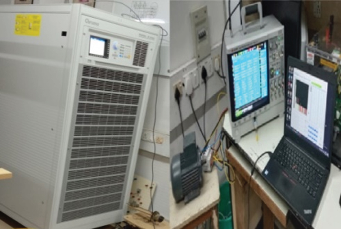
Hardware setup in the Laboratory.
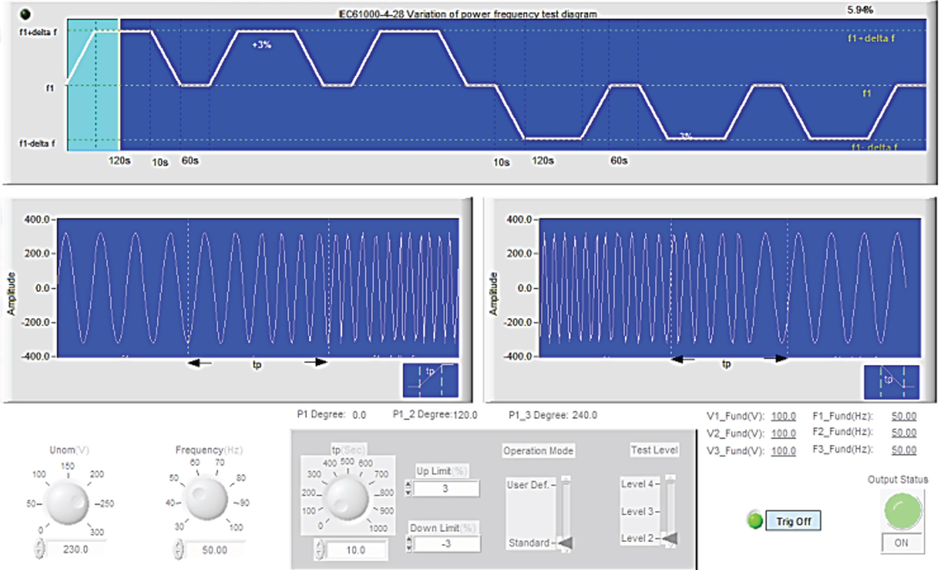
Visualization of Variation of power frequency as per IEC 61000-4-28.
For a sweep in frequencies at different intervals the change in magnitude of the current drawn by the Load is observed. Figure 4 represents the sweep in frequencies for fundamental frequencies of 50 Hz and 60 Hz of Class1, Class 2 and Class 3.
Modelling of the harmonics in the system using fuzzy logic controller
The FLC regulates the operation by integrating the human intelligence into an arrangement consisting of input and output relation. With the action of system operation the rules and Membership function (mf) are achieved. The rules are created based on the results obtained under the various test conditions of Hardware implemented. With increase in number of the rules as per the bounded conditions, the better performance can be expected from the FLC. In this fuzzy logic controller the major process possess Fuzzification, Reasoning and Defuzzification. Figure 5, represents the basic fuzzy interference system implemented for simulation.
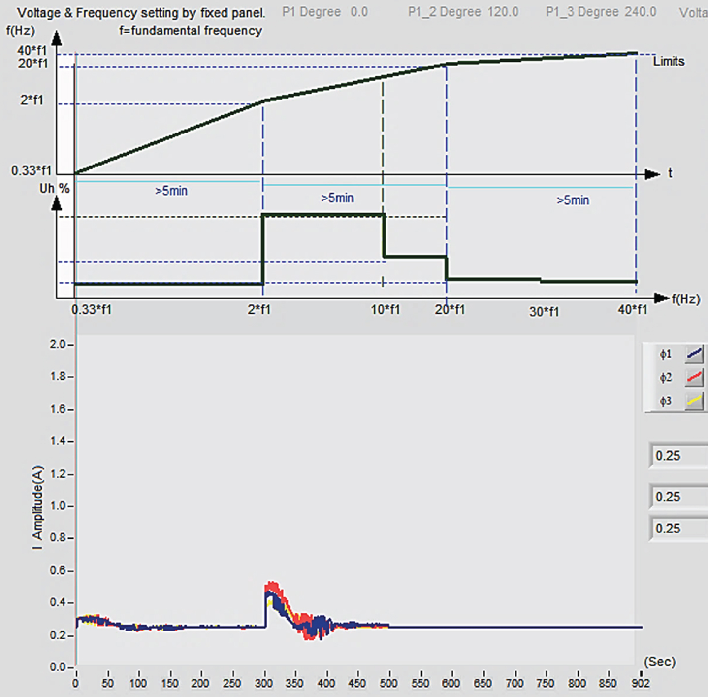
Visualization of sweep in frequencies.

Fuzzy Interference System.
Process of transforming an input crisp value in to a fuzzy value which is achieved from knowledge base information is termed as Fuzzification. In spite of different curves available, the triangular curve is used for the process of Fuzzification in this simulation. These varieties of Membership functions can be conveniently implemented by embedded devices which are defined mathematically with distinct parameters. For enhancing the performance of the fuzzy logic controllers, either the parameters or the membership functions shape can be maintained. By selecting the membership functions for the fuzzy sets the Fuzzification begins [14–16].
Fuzzy reasoning
Fuzzy reasoning depends on rules of fuzzy control and its inference. This rule base is the expert knowledge on by means of controlling the object. Fuzzy controllers belong to the Mamdani’s controllers and the adopted fuzzy rules are if-then rules. The fuzzy rules for Sweep in Frequencies for 50, 60 Hz in Class 1, Class 2 and Class 3 Equipment can be generated as shown in Tables 5.1 and 5.2 represents the Fuzzy rules for Interharmonics at different classes of Equipment’s.
Fuzzy Rules generated for sweep in frequencies at 50 Hz, 60 Hz in different classes of Equipment
Fuzzy Rules generated for sweep in frequencies at 50 Hz, 60 Hz in different classes of Equipment
Fuzzy Rules generated for sweep in frequencies at 50 Hz, 60 Hz in different classes of Equipment
The response of fuzzy reasoning is a product of fuzzy set. However, every regulatory task should signify the presence of crisp value at the output of fuzzy controller. Defuzzification is defined as the Process of converting the fuzzy output set back into the crisp values.
Simulation results of the harmonics in the system
Numerous experimental and simulation results are obtained for Distribution network in which three phase 1 hp Induction motor is connected as a Load. Some of the results related to harmonics are presented below.
From Fig. 6.1 (a), it represents the steady state voltage, current and power respectively for a fundamental frequency of 49.9 Hz in the network. From Fig. 6.1 (b), the harmonic content in three individual phases up to a count of 40 can be observed and Fig. 6.1 (c) it can be observed that the change of magnitudes (average and rms values) at different range of harmonic frequencies at a particular phase.
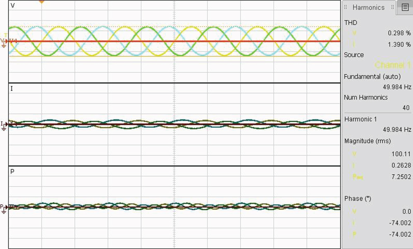
Steady state operating voltage, current and power.
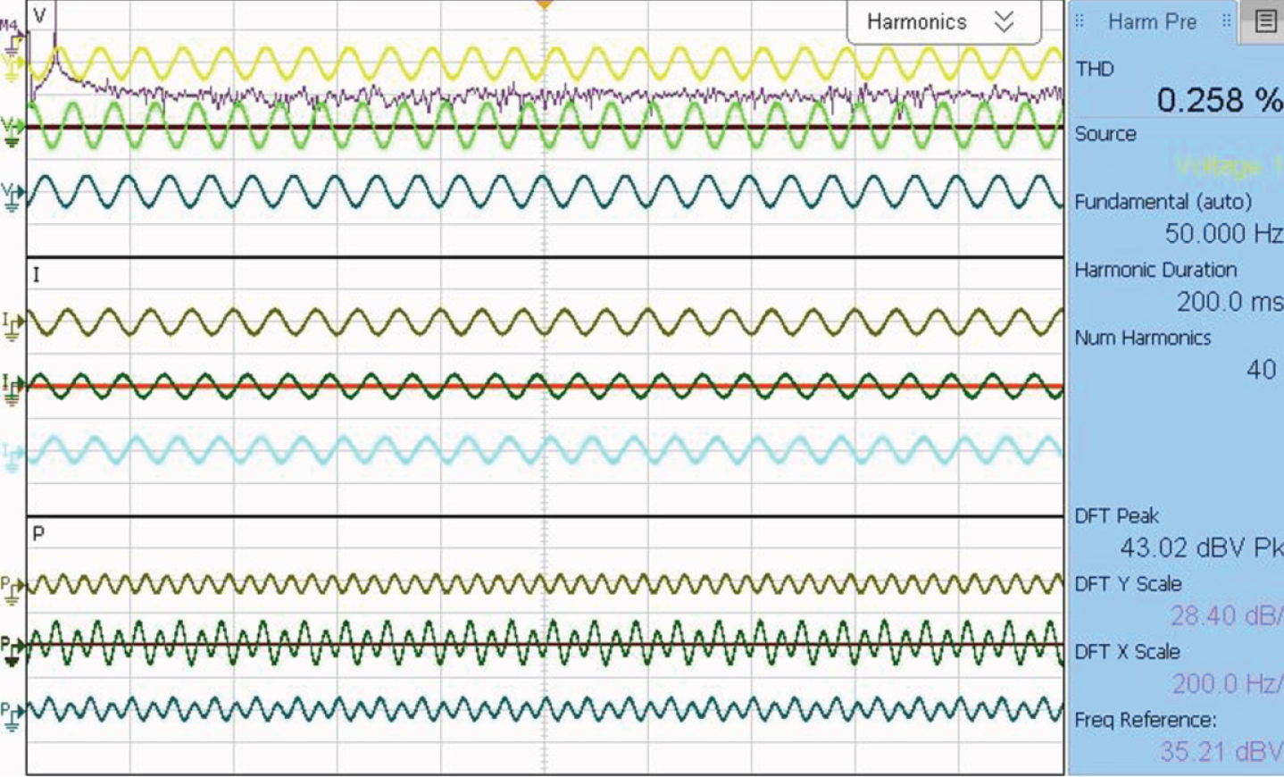
Injection of Harmonics for duration of 200 ms.
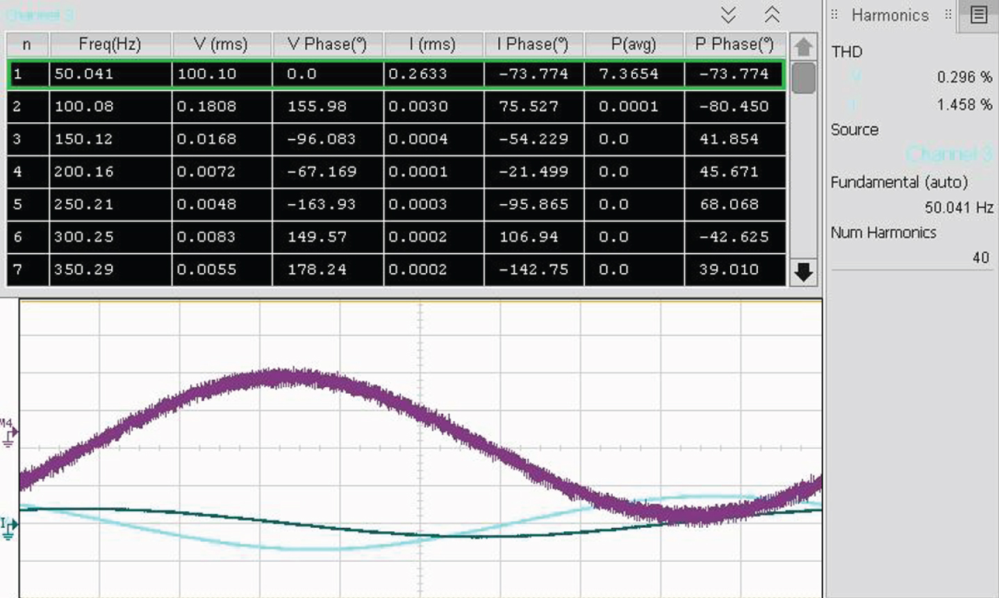
Voltage, current and Power magnitudes of Harmonics at different ranges of its frequencies.
Figure 6.1(d) and (e) represents the Odd ordered Harmonic spectrum at Voltage, current and power in the network with a THD of 0.28% and 2.44% respectively which is appears in bar charts for a 40 number of harmonics (odd order). From Fig. 6.1 (f) and (h) three individual Phase harmonic Voltage, current and power waveforms with a THD of 11.33% and 19.26% respectively in the network for a harmonic duration of 200msin the distribution network which is connected to three phase 1 hp induction motor.
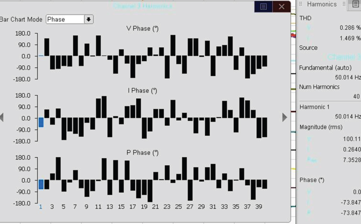
Odd ordered Harmonic spectrum at Voltage, current and power in the network with a THD of 0.28%.
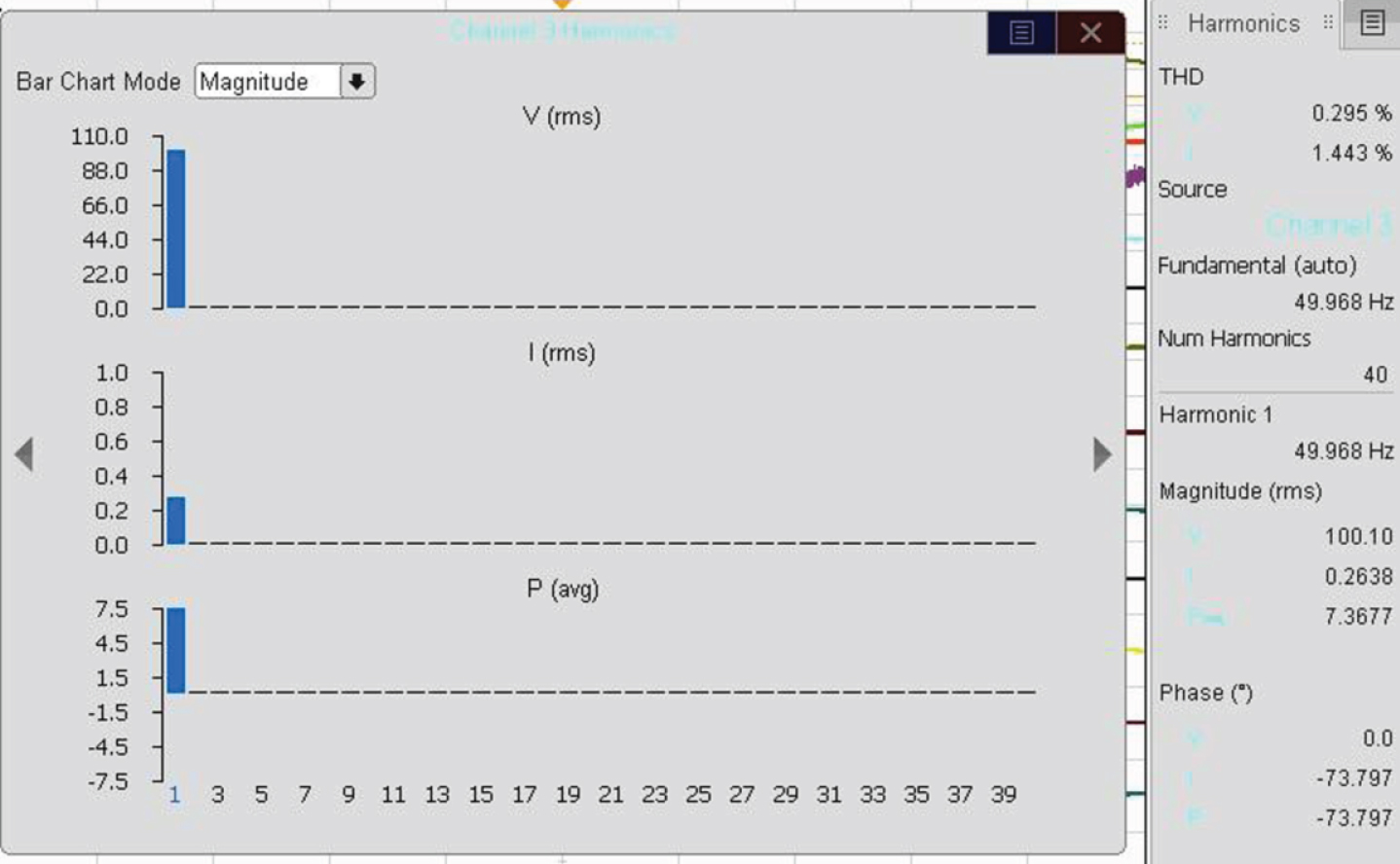
Harmonic spectrum of Voltage, current and power in the network with a THD of 0.28%.
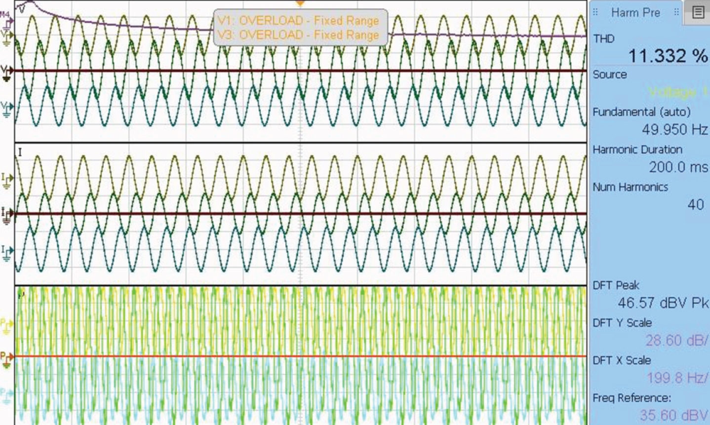
Three individual Phase harmonic Voltage, current and power waveforms with a THD of 11.33% in the network.
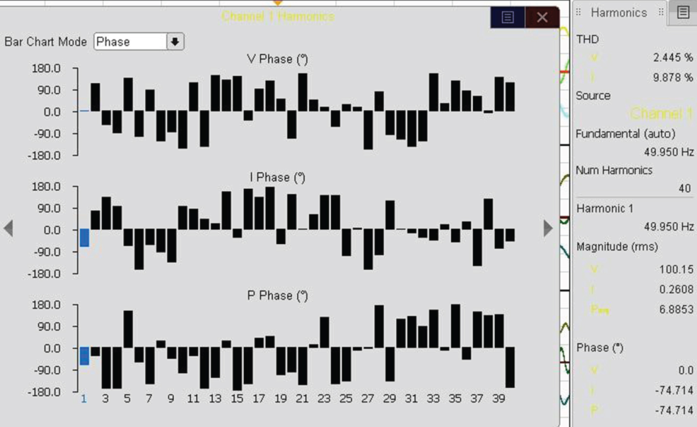
Odd ordered Harmonic spectrum of Voltage, current and power in the network with a THD of 2.44%.

Three individual Phase harmonic Voltage, current and power waveforms with a THD of 19.26% in the network.
From Fig. 6.2 and 6.3, it can be observed that the Interharmonics and Harmonics varies accordingly when there is reduction in nominal voltage at the supply mains under any abnormal conditions and the maximum amount of loss reached under this condition is 5% either in 50 Hz or 60 Hz. From 6.2 (c) it is observed that, at the initial frequency the maximum amount of loss is 9% either in 50 Hz or 60 Hz and from 6.2 (e) the maximum of loss is 14% either in 50 Hz or 60 Hz due to the loads connected at the point of common coupling (PCC).
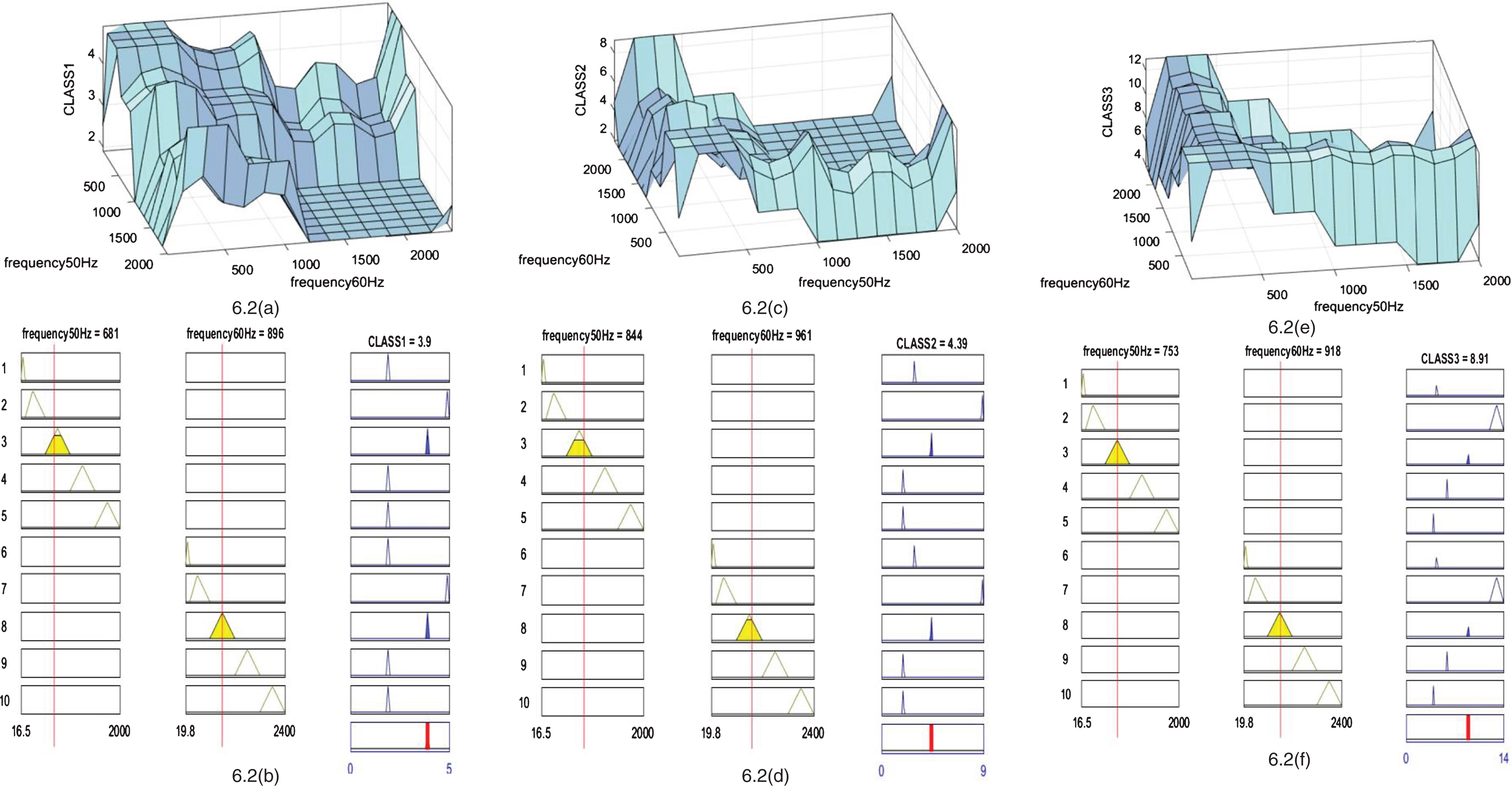
Sweep in frequencies Surface view at (a) class 1 equipment (c) class 2 equipment and (e) class 3 equipment at 50 Hz and 60 Hz frequencies and Rule viewer at (b) class 1 equipment, (d) class 2 equipment and (f) at class 3 equipment at 50 Hz and 60 Hz frequencies.
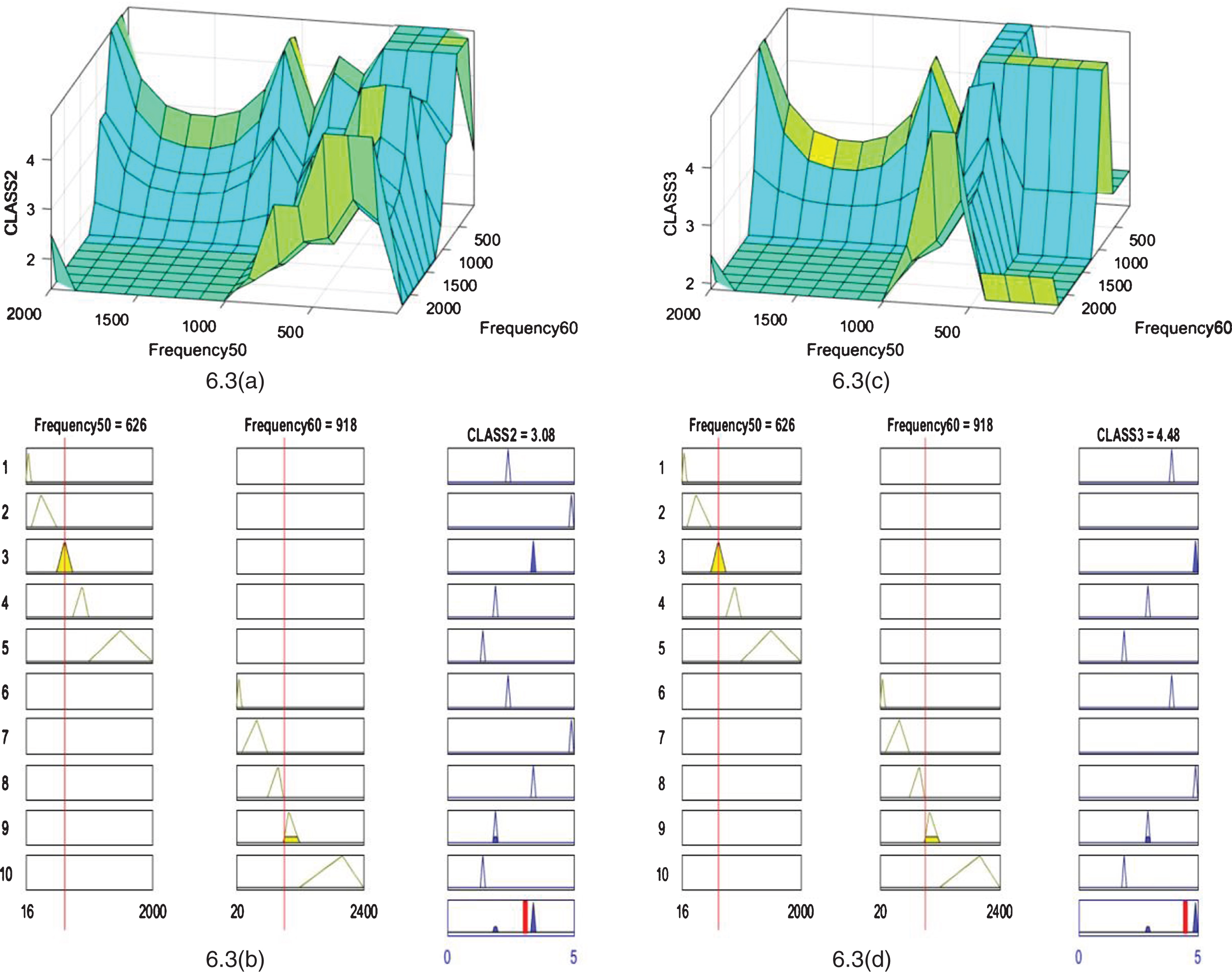
Surface view of Interharmonics in (a) class 2 equipment and (c) class 3 equipment at 50 Hz and 60 Hz frequencies and Rule viewer of harmonics in (b) class 2 equipment, (d) class 3 equipment at 50 Hz and 60 Hz frequencies.
In this paper, major PQ problems that affect the electrical power system especially, Individual Harmonics, Inter harmonics and frequency variations were inspected. The analytical results were presented during experimental performance characterization under each test as per the IEC 61000 standards, which will provide a better understanding of the characteristics. Simulation of power quality issues with the obtained results using MATLAB Simulink is implemented for the analysis of the Harmonic at different THD levels. This characterization can benefit in future development for power quality issues monitoring and for the transfer of knowledge between customers, utilities, and manufacturers of the equipment.