



Abstract
An Artificial Neural Network (ANN) based Space Vector Pulse Width Modulation (SVPWM) for five level cascaded H-bridge inverter (CHBI) fed grid connected photovoltaic (PV) system. The multilevel inverter topologies are offers better performance compare conventional two level inverter like reduced total harmonic distortion, less electromagnetic interferences and voltage stresses across switches are low. The ANN based SVPWM generates the switching pulses for cascaded H-bridge inverter; it improves the accuracy in reference vectors tuning and identification, which leads to improve the inverter output voltage, better utilization of dc-link voltage and controlled output current. The ANN control makes the implementation of SVPWM becomes simple and minimizes the intricacy in tracking reference vector and calculation of switching time; it is suitable for any type of non-linear systems. This proposed system is energized using PV system and it is boosted using dc-dc boost converter, and the output of CHBI is synchronized with grid connected system using coupled inductor. The simulation and experimental results of ANN based SVPWM for CHBI is verified using simulink-matlab and DSP processor.
Keywords
Introduction
In modern days the power electronic converters become key responsibility in the field of engineering and also very close relation with other fields like mechatronics, automobile, Flexible AC Transmission system devices, High Voltage DC system and renewable based applications [1–3]. Nowadays there is a need of large amount power requirement for industrial and variable speed drive applications. To meet the power requirement, the conventional two level voltage source inverters are implemented [4]. The number of drawbacks is identified, when conventional two level inverter is functional for medium voltage (MV) and high power (HP) appliances. To eliminate these drawbacks, the multilevel inverter topologies are introduced [5, 6]. The MLI is not only attains high power/voltage ratings, but also facilitates the employ of renewable energy sources. The different renewable source includes photovoltaic system, wind energy and fuel cells can be effortlessly interfaced to a MLI for a high voltage and power functions [7, 8]. It includes various advantages like reduced total harmonic distortion, low voltage stress across the semiconductor devices, minimized common mode voltage, Lower switching frequencies can be used and hence reduction in switching losses, lower EMI issues and dv/dt issues [9, 10]. The number of semiconductor devices is connected to obtain the higher number of level with minimized harmonic level and reduced odd order harmonics [11, 12].
The alternative MLI topologies with minimized number of passive components compare to other classical multilevel inverter is known as cascaded H-bridge inverter [13]. It is the combination of series and parallel connection of full bridge inverter circuit. Generally individual phase of CHBI necessitate ‘m’ number of applied dc sources for ‘2m+1’ level in applications that involve power transfer applications [14]. These dc sources are assumed to have identical amplitude ranges. This type of inverter topology are used for reactive power compensation and doesn’t need any clamping diodes or voltage balancing capacitors, which doesn’t have any voltage balancing problems [15]. The numerous inverter topologies and control strategies have been projected.
Generally in recent years, the usage of soft computing methods are increasing to generate accurate and to obtain the desired outputs from the power electronics and power system applications [16]. The various soft computing methods were implemented for various real time problems [17]. An artificial neural network is based on a collection of various devices or a node, which is called as artificial neurons, which slackly connected form the neurons in a biological system brains. Each device or nodes connection, like the synapses in a biological brain, can transmit a signal to other neurons [18]. An artificial neurons schemes that collects a signal then processes the collect signal to obtain the desired output from the system and can signal neurons connected to it. Artificial neural network algorithm utilized to obtain the desired output and to improve the accuracy of various parameters from the system [19].
Numerous PWM methods were executed for assorted converter and MLI topologies, which are used to organize the semiconductor devices; it leads to organize different restrictions of the inverter and hybrid electric-drives [20]. Among various PWM methods, SVPWM affords superior recital due to enhanced exploitation of dc-bus voltage, abridged THD level, noise diminution and control variables used straight to recognize switching state vectors in a hexagonal or circular area or three dimensional regions [21].
In this paper, ANN based SVPWM for five level CHBI fed grid-connected photovoltaic (PV) system. The structural diagram of proposed system is exposed in Fig. 1. The objective of this system is generates the switching pulses for cascaded H-bridge multilevel inverter using ANN based SVPWM to increase the precision in reference vector tracking, improve output voltage and controlled output current, reduced THD and better utilization of dc link voltage. This proposed system is energized using PV system and it is boosted using dc-dc boost converter and output voltage of CHBI is synchronized with grid connected system using coupled inductor.

Structural diagram of ANN based SVPWM for 5-level CHBI.
PV modeling and MPPT algorithm is discussed in Section 2. Section 3 deals switching of Five level Cascaded H-bridge Inverter and ANN based SVPWM is explained in Section 4, Simulation and Experimental results are discussed in Section 5 and 6 respectively.
A PV array includes the number of photovoltaic cells are connected in parallel and series manner. Series connected PV cells are accountable for escalating the voltage of the system and parallel connected PV cells are dependable for escalating the current of the system [22]. Classically a PV cell can be modeled by a current source and an overturned diode associated in parallel to it. It has the own series and shunt resistance of the PV cell, which is shown in Fig. 2a.The photovoltaic system output current is written as,

PV system a) Circuit for PV system b) I-V curve.
where Ia-reverse current of diode, q-current charge, Vp-voltage across diode, n-Boltzmann system constant and R- system temperature, from Equations (3) and (4),
In order to modeling the PV panel, it necessitates two diode models but in the projected technique, which is inadequate to the single diode model [20]. Also, the resistance is high and can be abandoned during the track of the study. The Current and Voltage curve of a PV module with irradiance variation is shown in Fig. 3. Perturb & observe MPPT technique is used to track the maximum power point from PV system for the dissimilar solar radiations and system temperature.

Current and Voltage characteristics of a PV module with irradiance variation.
The P&O technique affirm that when the working voltage level of the PV panel is anxious by a diminutive addition, if the ensuing modify in power ΔP is optimistic (ΔP>0), then it modify to budge in the track of maximum power point and it keep on disturbing in the same direction. If ΔP is pessimistic (ΔP<0), it leaves away from the direction of maximum power and the indication of perturbation completed has to be distorted. The flowchart for P&O technique is exposed in Fig. 4.

Flow chart of Perturb & Observe technique.
The CHBI was designed based on series and shunt connection of individual full bridge circuit. Generally CHBI is mostly utilized for wide range of applications. Due to more flexibility and modulation range variation, which is more suitable for high power applications, specifically for FACTs controllers, power quality and other power system applications. By combining many isolated voltage ranges the nearly sinusoidal output voltage is obtained. Also by adding many H-bridge systems, the amount Var range increases without redesign any power input stage and has an advantage of individual H-bridge converter circuit failure identification. In Fig. 5 shows three phase five level CHBI circuit. The output phase voltage is synchronised by the addition of voltage engendered by the different voltage cells.
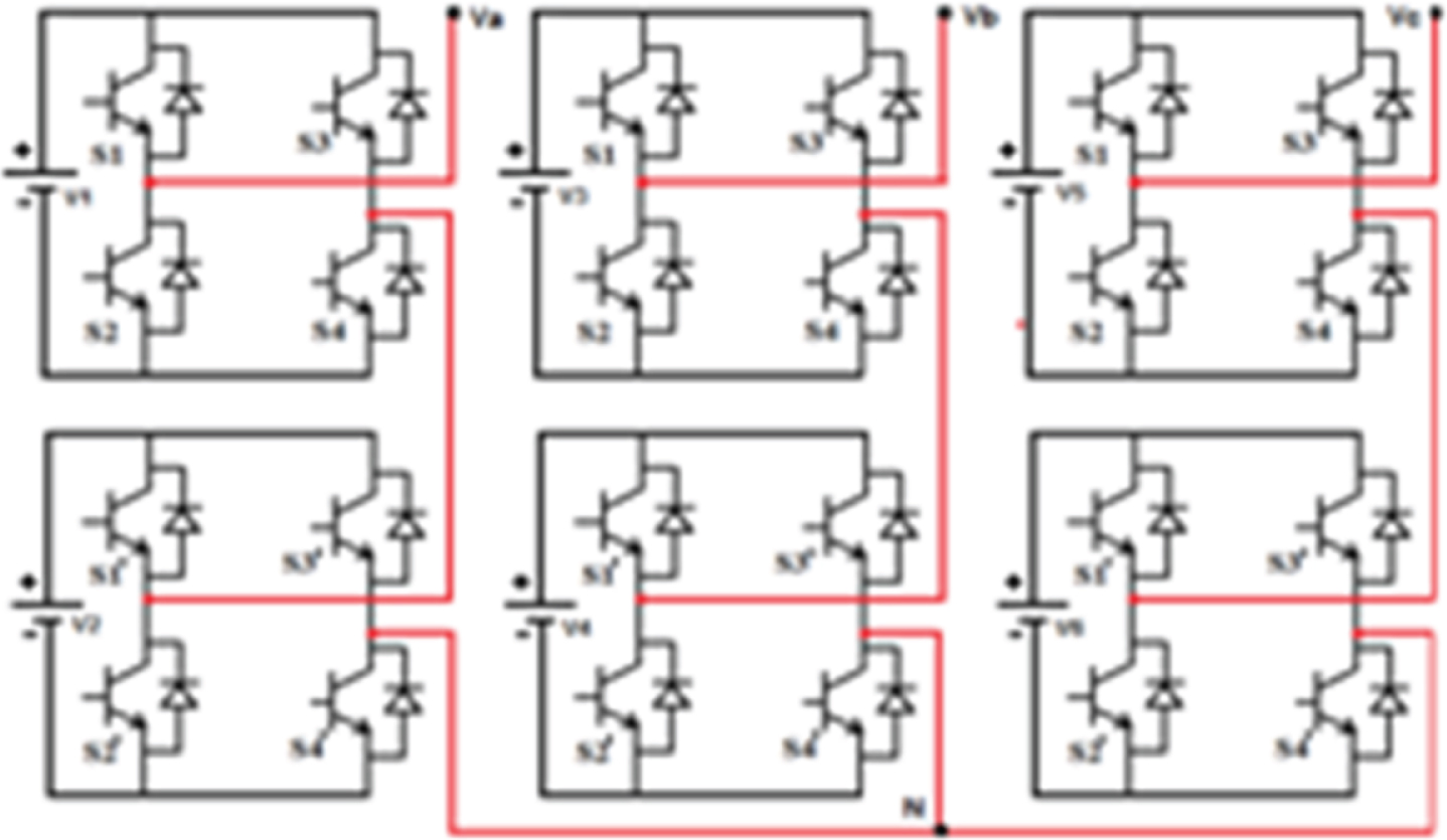
ThreeiPhase Five level Cascaded H-bridge Inverter.
Generally in 3-level CHBI, each single phase circuit generates output of+Vdc, 0, -Vdc (Positive output voltage, zero voltage and negative output voltage. Similarly for 5-level inverter shown in circuit obtains the voltage of+2Vdc, Vdc, 0, -Vdc, -2Vdc. The obtained staircase output is almost sinusoidal exclusive of using any filter circuits. The Table 1 shows the switching state vectors of 5-level cascaded H-bridge inverter, similarly all three phases can be operated, which includes 125 switching state vectors.
Switching state vectors of 5-level CHBI
The description of CHBI used for real power converters like ac to dc or dc to ac conversion, the cascaded inverter system needs divide dc sources. This CHB-MLI structure is much suited for renewable energy as input sources like PV system, biomass, fuel cell, etc. And connecting the separated dc sources between 2 back to back converters are not possible, since short circuit will occur when not switching simultaneously while connection dc source between two converter circuit.
The advantage of CHBI includes the regulation of dc source is very simple, Modulation range control can be accomplished. Unlike diode clamped multilevel inverter and capacitor clamping multilevel inverter where the personage phase leg control must be controlled separately using various pulse width modulation algorithms, requires condensed number of power equipments to achieve same level output voltage, soft switching method is used, to reduced the size, losses due to resistors and minimize the switching losses. This topology has disadvantages of requires communication between the various full bridge circuits to maintain the synchronize between the reference and carrier waveforms, need of separate dc sources may leads to voltage balancing problem.
The artificial neural network is one the soft computing technique, which is used to tune or control any parameter of power system and power electronics based applications [23]. The artificial neural network based SVPWM generates the switching pulses for three phase five level CHBI; it improves the accuracy in reference vectors tuning and identification, which leads to improve the inverter output voltage, better utilization of dc-link voltage and controlled output current. The ANN control makes the implementation of SVPWM becomes simple and reduces the difficulty in tracking the reference vectors and calculation of switching times; it is suitable for any type of non-linear systems.
The reference vectors calculation for SVPWM implementation is tuned using artificial neural network. The Fig. 6 shows the reference vectors tuning using ANN algorithm for SVPWM technique; in that input a,b and c are obtained from the output of cascaded H-bridge inverter. In the hidden unit of ANN system, the various parameters like switching frequency (Ts), carrier frequency (Cn), magnitude (M), angle (K) and various sectors located in hexagonal region (Sn), which is used to obtain the tuned reference vectors for SVPWM implementation.
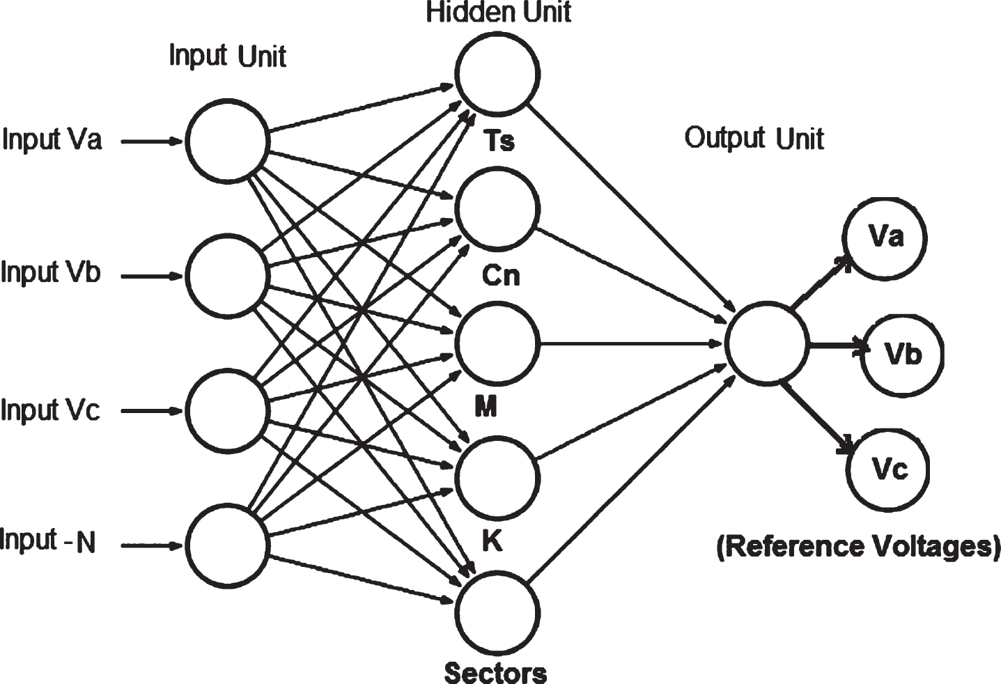
Reference vectors tuning using ANN algorithm for SVPWM technique.
The Fig. 7 shows the block diagram for process of ANN based SVPWM control, which includes the input reference tuned from ANN system. It converts three phase a-b-c coordinates to two phase d-q coordinates using parks transformation. From the tuned reference vectors, the magnitude and angle is determined using total switching frequency. The switching pulses are generated using sector and triangle identification from the hexagonal region.
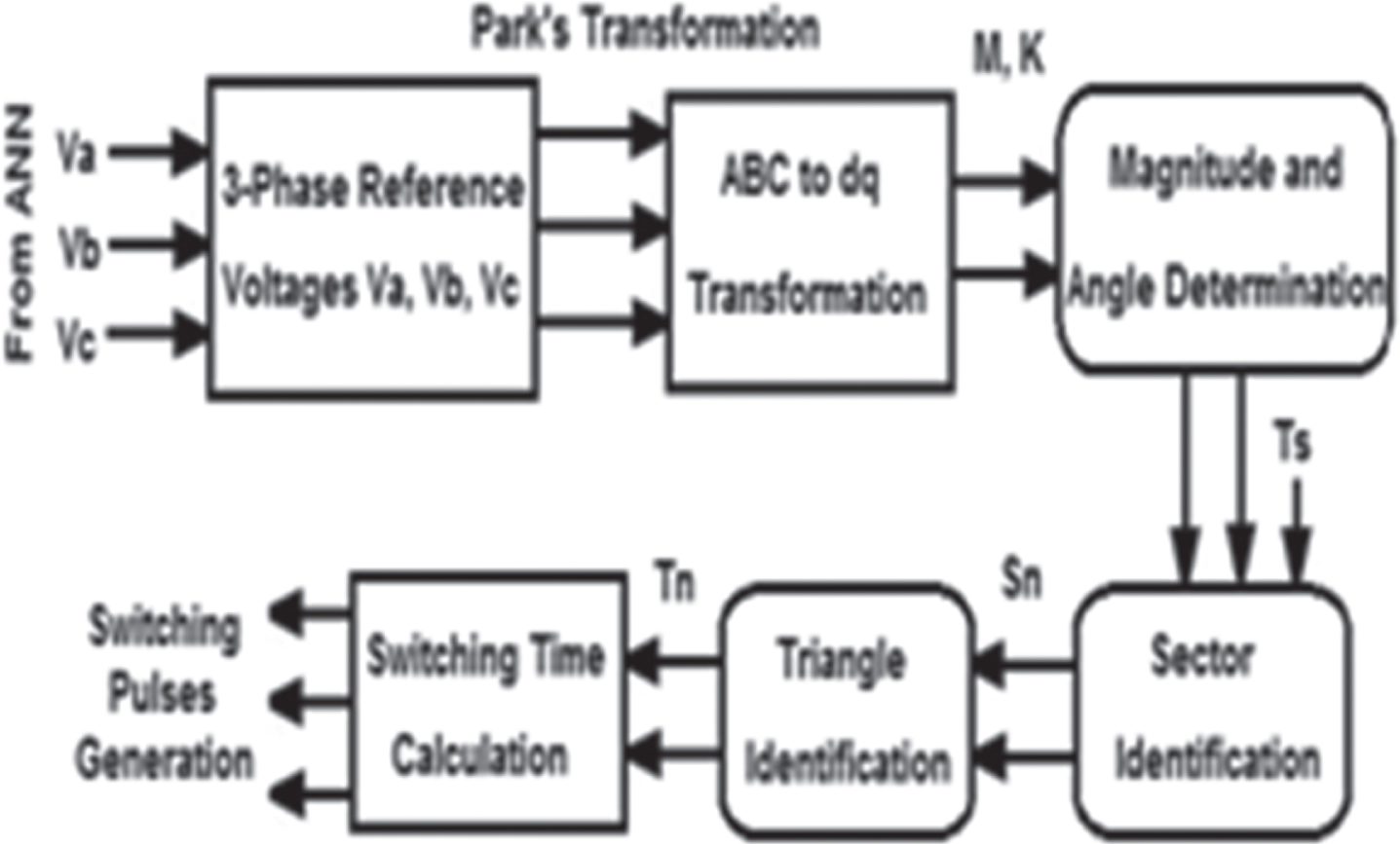
Block diagram for process of ANN - SVPWM control.
The 3-phase 5-level CHBI comprises absolutely 125 switching state operations, which consists of 5 null (or) zero switching state vectors, 60-small switching state vectors and 30-medium switching state and large switching state vectors, which is shown in Fig. 8. In SVPWM algorithm, the hexagonal area is engaged by to declare all the switching state vectors, in that superfluous switching states are only probable in small state vectors. The scheme includes of six sectors, each sector has four triangles.
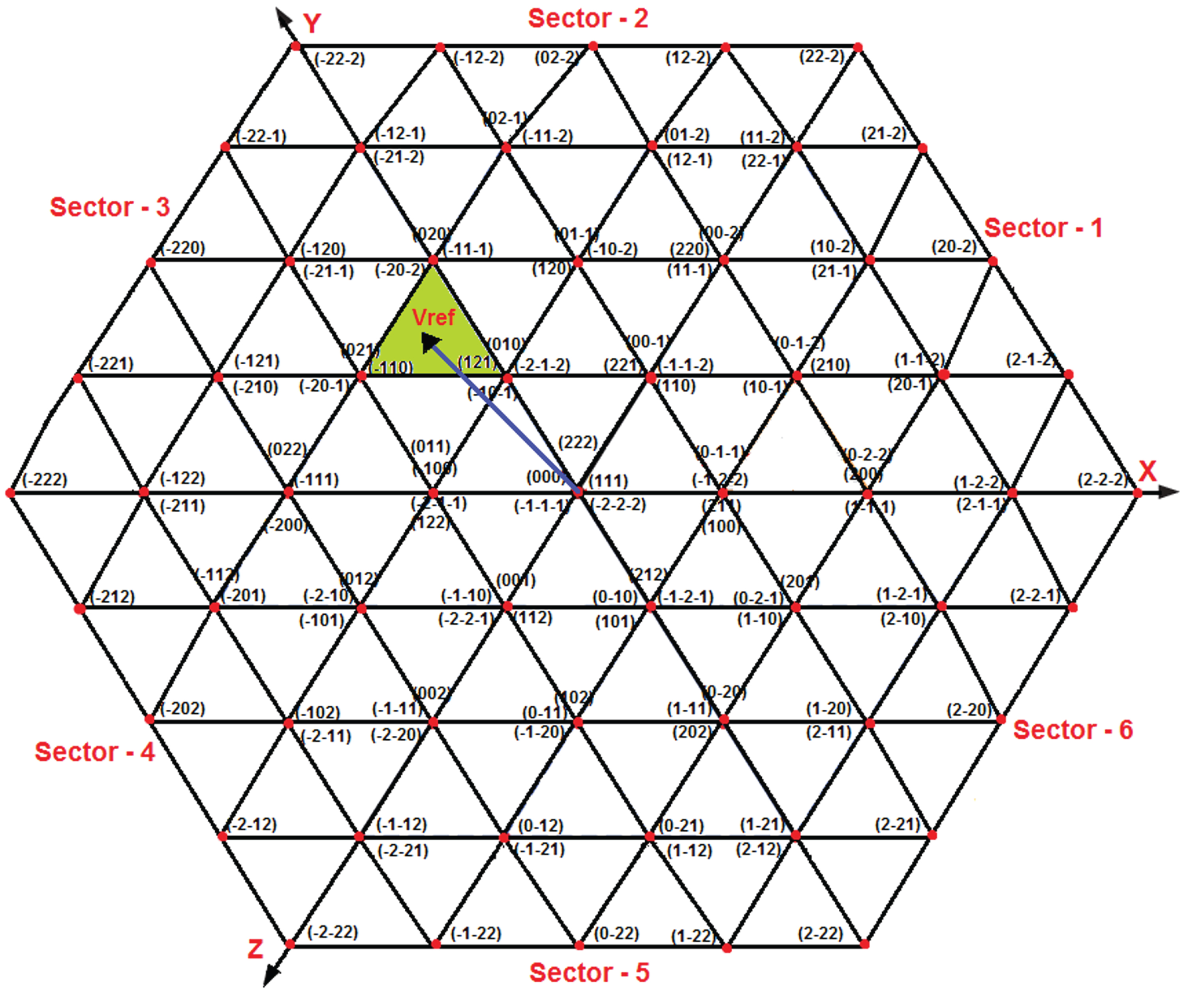
Representation of Hexagonal SVPWM algorithm.
In this algorithm, the tracking of reference vectors to progress the inverter output voltage and to organize the output current, this is represented as,
Here V* – reference state vectors and δS1, δS2, and δM1 are small switching state 1, small switching state 2, and the medium switching state of various triangles located in the hexagonal area.
The various steps for tracking the reference vector are as follows: (i) find the sector position; (ii) Track the triangle position and (iii) execute the calculation of switching time, which is exposed in Fig. 9. The total switching time is expresses as,
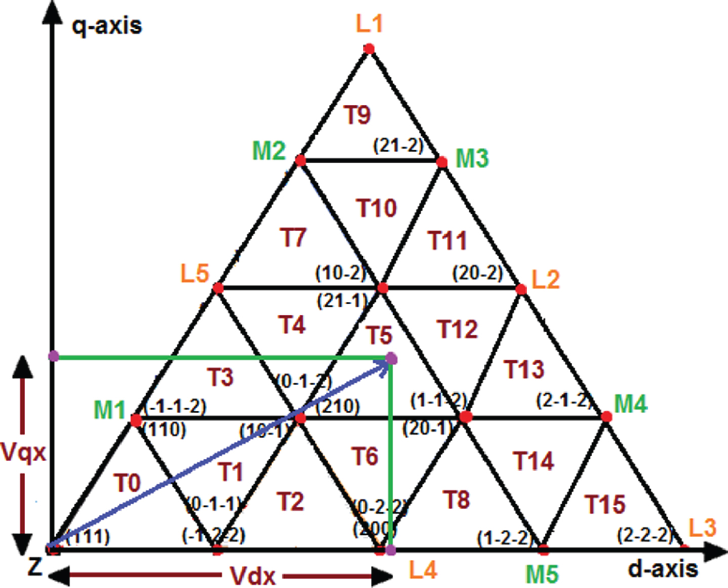
Switching time calculation for sector 1 using NTV scheme.
The positions of M3 and M4 with respect to M1 are ranges varies (1.0 h) and (0.5 h) correspondingly. Alternative of magnitude into the above equation, the final equation is
The switching time for the various triangles can be premeditated using the above Equations (7)–(11). Based on the switching time, the switching pulse for 3-phase 5-level CHBI is generated. The process of SVPWM implementation shown in Fig. 10.

Process of SVPWM implementation.
The proposed artificial neural network based SVPWM for 3-phase 5-level CHBI fed grid connected photovoltaic (PV) system is simulated using matlab software. The proposed system 5-level cascaded inverter is energized using PV system and dc to dc boost converter. The output voltage of cascaded inverter is synchronized with grid connected system using coupled inductor. The Fig. 11a shows the output voltage of photovoltaic system (101.5 V) with variation solar radiation from 400–500 W/m2 and temperature variation of 30–40 degree. The Fig. 11b shows the boosted voltage using dc to dc converter, which is boosted to 200.5 V.
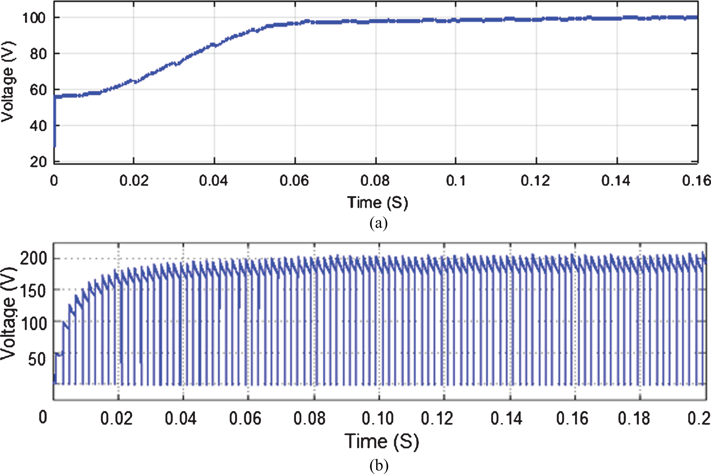
(a) Output voltage of Photovoltaic system (b) Boosted voltage using dc-dc converter.
The Fig. 12 shows the five level CHBI using ANN based SVPWM control method; in that Fig. 12a shows the output voltage of three phase five level CHBI with 200 V and Fig. 12b shows the output current of three phase five level CHBI with 4.2 A. The proposed ANN based SVPWM control technique used to switching pulse generation for 5-level CHBI, which is shown in Fig. 13. The THD examination of proposed 5-level CHBI with ANN based SVPWM control method is shown in Fig. 14. In that Fig. 14a shows the THD examination for output voltage with 0.21% and THD for output current with 2.75% is exposed in Fig. 14b. The Fig. 15 shows the synchronization of 5 level CHBI output voltage and current with coupled inductor. It leads to improve the synchronization between the cascaded inverter and grid connected system.
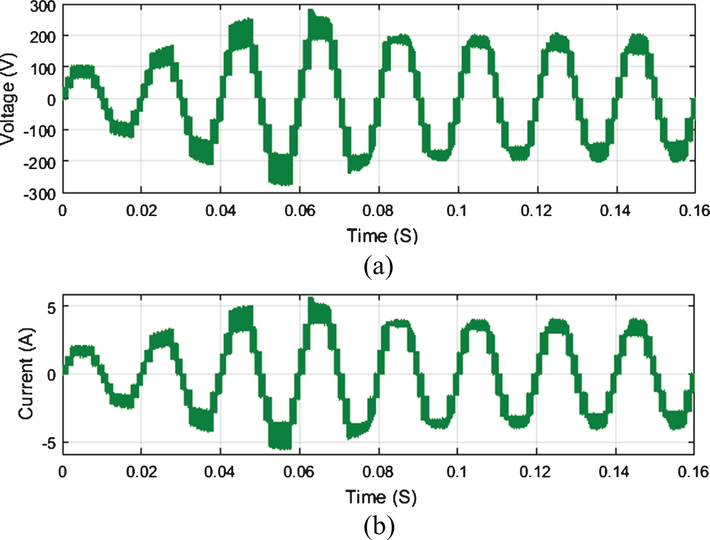
5-level CHBI (a) Output voltage (b) Output current.

Switching pulse generation using SVPWM.
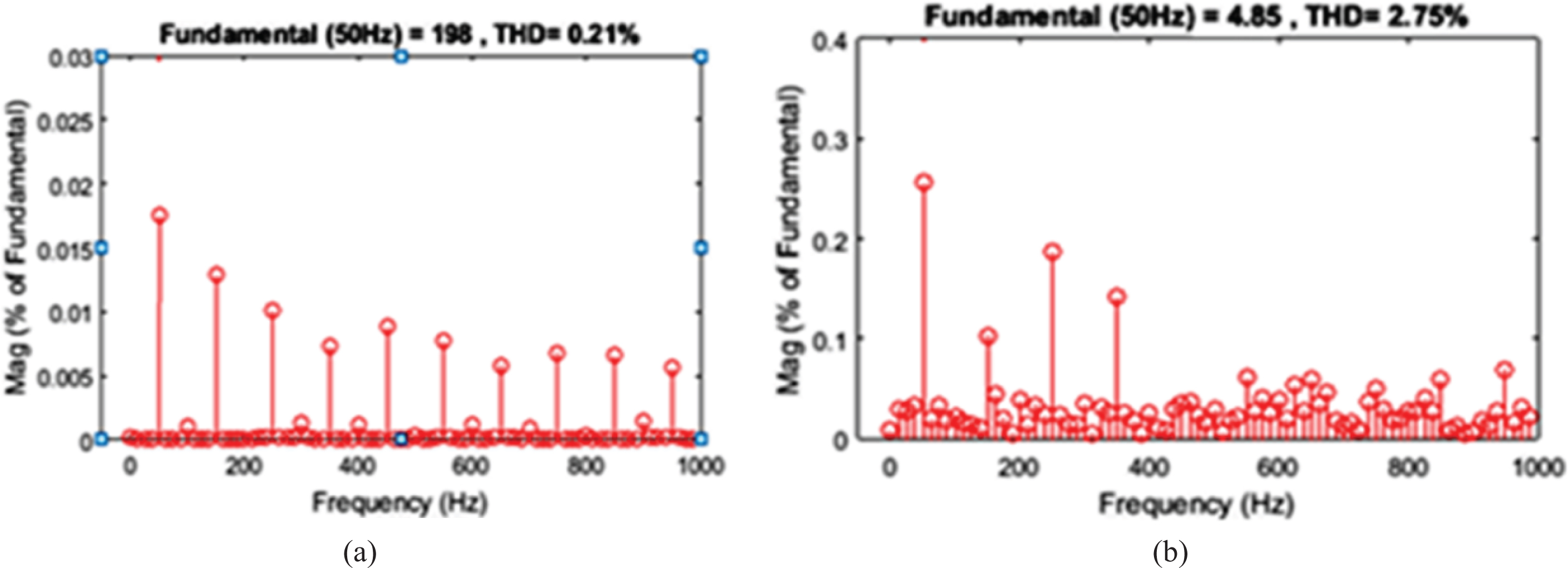
THD examination (a) Output Voltage (b) Output Current.
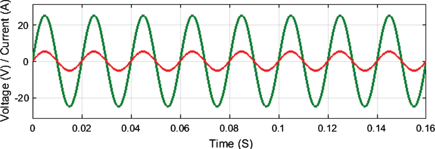
Synchronization of CHBI inverter voltage and current with coupled inductor.
To endorse the simulation results of projected ANN based SVPWM for three phase five level CHBI is designed and tested using Digital Signal Processor (DSP-2812). The controlled power switches used in the 5-level CHBI as IGBT devices with 16A rating.
The Fig. 16 shows the hardware results of proposed system, in that Fig. 16a shows the hardware output voltage of three phase five level CHBI with 200 V and the Fig. 16b shows the hardware output current of three phase five level CHBI with 4.1 A. The synchronization of five level CHBI output voltage and current is exposed in Fig. 17.
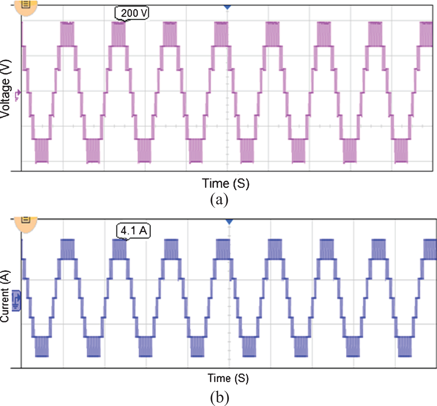
Hardware results of 5-level CHBI (a) Output voltage (b) Output current.
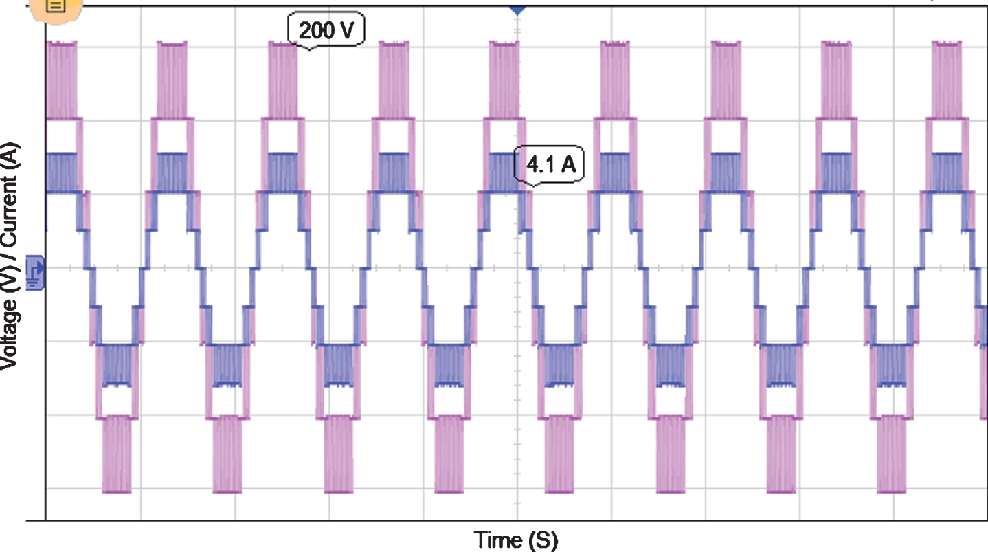
Synchronization of inverter output voltage and current.
The hardware results of three phase five level CHBI with coupled inductor (4 mH) are shown in Fig. 18. In that Fig. 18a shows the hardware output voltage of cascaded inverter with coupled inductor is 200 V and hardware output current of cascaded inverter with coupled inductor of 4.1 A. It leads to improves the synchronize between the cascaded inverter and grid connected system. In Fig. 19 shows the comparison of reference vector tuning for various controls like artificial neural network, fuzzy logic controller and PI controller. Among these controllers ANN provides better tuning of reference vector for switching pulse generation using SVPWM control. This proposed ANN based SVPWM provides better THD reduction for CHBI evaluated to predictable PWM methods. The comparison results are shown in Table 2.

Hardware results of five level CHBI with coupled inductor (a) Output voltage (b) Output current.

Comparison of reference vector tuning for various control methods.
Comparison of results
In this paper, an Artificial Neural Network based SVPWM for 5-level CHBI fed grid connected photovoltaic (PV) system. The ANN based SVPWM generates the switching pulses for power switches placed in CHBI; it improves the accuracy in reference vectors tuning and identification, which leads to progress the inverter output voltage level and controlled output current is achieved. The ANN control makes the implementation of SVPWM reduces the difficulty in tracking of reference vector and calculation of switching time; it is suitable for any type of non-linear systems.
The highlights of the paper: ANN based SVPWM is implemented for three phase five level CHBI. THD is abridged to 0.21% for output voltage and 2.75% for output current of CHBI. This proposed system leads to diminish the difficulty in calculation of switching time and reference vector tuning using ANN algorithm. It proves the synchronization between the cascaded H-bridge inverter and grid connected system using coupled inductor. ANN based SVPWM is suitable for all type of symmetrical and asymmetrical inverters.