
Abstract
Athletes’ sports detection has a heavy pressure on athletes’ training and post-injury rehabilitation. In the traditional mobilization test, there is no effective combination of exercise and rehabilitation, which directly leads to the athlete’s physical health cannot be guaranteed. Based on this, this study combines the current situation of the athletes’ field and the training ground, and uses monocular vision as the video input interface, and combines the monocular vision technology in the research. Moreover, in the research, this paper combines the human body model to construct an athlete’s human body model that adapts to monocular vision. At the same time, this paper combines the image processing technology to transform the image of the monocular visual athlete into a skeleton model, so as to realize the modeling of the athlete’s movement. In addition, this paper combines the model to explore the indoor and outdoor athlete recovery techniques and validates the model by experiment. The research shows that the research model has certain effects, which can meet the actual needs, and can provide theoretical reference for subsequent related research.
Introduction
It has good application prospects and potential commercial value in intelligent video surveillance, human-computer interaction, video conferencing, content-based image retrieval and virtual reality, and is one of the most active research directions in computer vision in recent years [1]. Moreover, it includes automatic detection of human targets in the video, extraction of motion features, description of behavior and semantic understanding, which belongs to the category of image analysis and understanding.
Human-computer interaction is a medium and dialogue interface for transferring and exchanging information between people and electronic devices (such as computers, mobile phones, multimedia, consumer electronics, tablets, etc.). The technology involves many disciplines such as computer science, psychology, cognitive science, sociology, and anthropology [2]. Moreover, it completes the functions of information management, service and processing for people, making the computer truly become an assistant for people to work, study and live, and it is developed along with the birth of the computer. At the same time, with the rapid development of computer information technology, it has stimulated people’s desire for more humanization and naturalization of human-computer interaction. Therefore, human-computer interaction has become one of the main research hotspots in the field of computer science and technology [3].
Human body three-dimensional motion recovery technology based on image and video has been a hot research topic in the field of pattern recognition and computer vision, and there has been a lot of work and research results [4]. The traditional human body three-dimensional motion recovery technology mainly uses multi-camera imaging to complete the matching tracking of human joint points and restore three-dimensional position information. Moreover, in multi-camera human motion tracking, it is necessary to ensure the relative spatial position between multiple cameras and the lighting conditions in the scene, and at the same time, it is necessary to determine which camera is used every moment. That is, the selection and integration of information between multiple cameras is a key issue in this technology. Therefore, in practical applications, some practical conditions are not suitable for research and analysis with multiple cameras. Monocular vision has the advantages of simple structure, non-contact, and no limitation of the scope of view. At the same time, it does not require a complicated global calibration process of multiple cameras. Therefore, how to solve the position and attitude under monocular vision has become an important research direction [5].
For sports, some large foreign sports stadiums have been monitored by multiple electronic devices. However, in most cases, there are still insufficient monitoring points, so the need for monocular visual monitoring accuracy is particularly important [6]. Especially for the monitoring of athletes’ movement process and the risk of injury that may exist in sports, it is very important to identify the effect of monocular vision. Based on this, this study analyzes the movement process of athletes based on monocular vision, and on this basis, develops corresponding recovery techniques.
Related work
Camera calibration is the most basic calibration in a vision system, and any vision system generally needs to determine camera parameters. Therefore, the first result of the calibration theory is the calibration of the camera. The camera calibration is used to determine the conversion relationship of the world coordinate system with respect to the image pixel coordinate system, and mainly includes an external parameter reflecting the conversion relationship between the world coordinate system and the camera coordinate system and an internal parameter reflecting the conversion relationship between the camera coordinate system and the image pixel coordinate system. Domestic and foreign scholars have done a lot of research on the calibration of cameras. According to the different calibration methods, it can be divided into traditional camera calibration methods, self-calibration methods and active vision-based calibration methods. Moreover, the most widely used traditional calibration methods are direct linear calibration and TSai’s two-step calibration. The direct linear calibration method was first proposed by Abdel.Aziz and Karara. The method is to establish and solve linear equations by defining intermediate variables to obtain the internal and external parameters of the camera [7]. Hall [8] applied the least squares method to the calculation process of the linear transformation matrix based on the direct linear calibration method, which improved the accuracy of camera calibration. Wang [8] proposed three different linear calibration methods for solving the external parameters of the camera; Zhuang et al. [9] gave a simple and improved radial alignment constraint method for camera calibration and obtained better calibration results. The linear calibration method assumes that the camera imaging model is linear during the calibration process and does not take into account factors such as machining errors and installation errors of the camera lens. Therefore, even if the linear calibration method has achieved a lot of research results, when the camera manufacturing accuracy is not high enough, the calibration results are still very different from the actual calibration data. In order to overcome the processing error of the camera itself, some scholars take the distortion of the camera into the calibration process based on the linear calibration method and study the calibration method of the nonlinear camera according to the camera distortion mechanism. Kim [10] and others have established a variety of lens distortion imaging models based on the characteristics of camera distortion. Batista et al. [11] used a special feature plane as a calibration tool, first given the initial values of the parameters in the camera, and then obtained more accurate internal and external parameters of the camera by means of parameter iteration. Compared with the linear calibration method, the nonlinear camera calibration method has a significant improvement on the camera calibration accuracy. However, in the calibration process, the method of numerical optimization may lead to the case where the iterative value does not converge.
Corner extraction is a relatively basic feature extraction technique in image post-processing technology, which has a wide range of applications in camera calibration and image matching. Depending on the position, the corner points can be further divided into dots and inflection points, and the inflection point is at a position where the curvature has a large change, and the dot is at the center of a region having a common feature (generally referred to as a threshold). Different types of intersections have different extraction methods. The existing intersection extraction methods mainly include MoraVec corner detection method, MIC corner detection method, Fors er corner detection method, corner extraction method and SUSAN corner detection algorithm [12]. The Moravec corner detection method is an operator that extracts point features using gray variance. The method needs to preset a threshold in the process of corner point extraction, and judges whether the candidate feature point is a corner point, and the threshold value is usually an empirical value. Therefore, the determination of the empirical threshold directly determines the accuracy of the corner extraction of the method. The operator is simple and fast, but sensitive to strong boundaries [13]. The basic principle of the MIC detection method is to detect the minimum brightness change value in the pre-circular window and compare it with the set threshold. If the minimum brightness change value is greater than a certain threshold, it can be considered as a corner point. The method has the characteristics of high precision, fast calculation speed, good stability and robustness to noise [13]. The Forstner corner extraction method is a commonly used point feature localization operator for photogrammetry [14]. The algorithm finds the point of the error ellipse close to the circle as small as the feature point by calculating the Rober’s gradient of the pixel and the gray covariance matrix of a window centered on the pixel. By performing a weighted centering operation within the optimal window, the positioning accuracy can be improved to the level of the sub-pixel. The disadvantage of this method is that the threshold needs to be determined, so it is susceptible to image grayscale and contrast changes. The corner detection method [13] uses the correlation between the corner points in the image and the curvature characteristics of the autocorrelation function describing the degree of gray change of the local image to locate the corner points. The method is simple in calculation process and has high stability and robustness. Therefore, the extraction of the corner points of the calibration plate in the camera calibration generally adopts this method. SUSAN corner extraction algorithm [14] is a method for corner detection using image gray information. The operator does not need to perform derivation and gradient calculation on the image and does not need to perform image segmentation on the image in the early stage and has integral characteristics. Therefore, the algorithm has the advantages of strong anti-noise ability, fast detection speed, accurate positioning, etc., and can distinguish different types of corner points. It can be seen from the above that different corner extraction methods have their own advantages and disadvantages. In the specific corner extraction process, the specific scene requirements and the type of corner points should be fully considered to select a specific detection method.
Theoretical basis of the algorithm
Coordinate representation
In higher geometry, there are many ways to define a space line. The common two methods are as follows. We assume that the homogeneous coordinates of two points A and B in space are [15]:
Then the linear equation can be expressed as
At the same time, the linear equation can also be expressed as a symmetrical form, as shown in Equation (2).
If there are two line equations l1, l2, as shown in Equations (3) and (4).
Assuming that the straight line l1 is perpendicular to the straight line l2, the common perpendicular equation can be expressed as the form shown in Equation (5) [16]:
In the formula:
Assuming that the straight line l1 intersects the straight line l2, the intersection of the two straight lines can be obtained by the simultaneous equation, as shown in Equation (6) [17]:
The three-dimensional measurement of points in space is carried out by means of “monocular double position”. The measurement principle is shown in Fig. 1. In the figure, C w is the world coordinate system, C i and C j are the tool coordinate systems for controlling the camera coordinate system, and C c 1 , C c 2 is the camera coordinate system when the tool is at the i, j position. The camera is controlled to capture images from the fixed point P and from two locations. According to the principle of camera aperture imaging, the image points of point P on the camera imaging plane of two orientations are P1, P2 respectively. Then the point P in the space should be on the line connecting P i , P j with its corresponding camera optical center O1, O2. Therefore, if we want to find the coordinates of point P in the world coordinate system C w , we only need to obtain the intersection coordinates of the space line O1P1, O2P2. The specific solution process is as follows [18]:
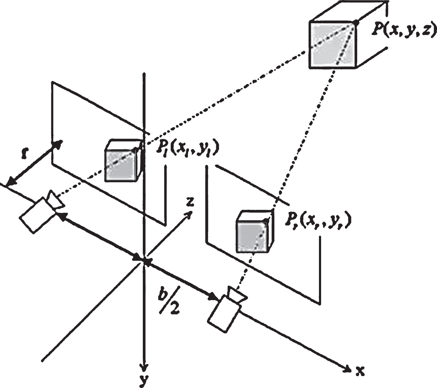
System working principle diagram.
We assume that when the tool is in the i, j position, the coordinates of the image formed by the spatial point P on the image plane are
f
i
, f
j
is the camera focal length. According to the definition of the 1.1-space linear equation, the linear equations in the corresponding camera coordinate system can be expressed as the form shown in Equations (7) and (8) [19]:
At this point, point P is on the line determined by the two camera coordinate systems, and we need to convert it into the coordinate space of the world coordinate system.
The representation of the two lines in the world coordinate system can be derived from Equations (9) and (10).
Where H is the pose matrix of the camera coordinate system relative to the tool coordinate system, which is generally a constant matrix. H
i
, H
j
is the pose matrix of the tool coordinate system relative to the world base coordinate system at the i and j positions, which are respectively [20]:
It can be calculated that the two straight lines can be expressed in the form of (11) (12) in the world coordinate system [21]:
In reality, due to camera distortion and environmental factors, there is an error in the actual measurement results. The biggest error comes from the distortion of the camera, and the camera distortion is mainly caused by the perspective distortion, which belongs to the inherent nature of the lens and cannot be eliminated. Depending on the precision of the camera manufacturing, the image captured by the camera will produce different degrees of distortion, but the high-precision positioning process generally has to undergo image correction and other operations to adjust the distorted image, which is one of the main reasons for camera calibration. In general, camera distortion can be divided into two main types: pincushion distortion and barrel distortion. As shown in Fig. 3, the pincushion distortion is a phenomenon in which the picture caused by the lens “shrinks” toward the center, and this phenomenon often occurs during use of the telephoto lens or the telephoto end of the zoom lens. The barrel distortion is a distortion phenomenon in which the image of the lens caused by the physical properties of the lens and the lens group structure exhibits a barrel shape expansion. This phenomenon often occurs during wide-angle lens or during use of the wide-angle end of the zoom lens. In this section, by analyzing the imaging principle and distortion principle of the camera, the pixel coordinates of the acquired target point are adjusted to improve the positioning accuracy of the monocular vision system [22].
The camera distortion imaging model is shown in Fig. 3, and the camera radial distortion model can be derived from Equations (13) and (14) [23]:
In the formula,
The relationship between image pixel coordinates x
u
and y
u
and camera image coordinates
It can be known from the combination of Equations (13)–(15)
Equation (16) is used to correct the straight lines f1, f2 in Equations (11) and (12), then a more accurate solution can be obtained [24].
In the figure, the subscript indicates the corresponding coordinate system, “w” indicates the world coordinates, “ c” indicates the camera image coordinates, and “ u” indicates the pixel coordinates. P is a point in the world coordinate system, p1 is a point in the acquired image coordinate system, and p is a point on the image where the point P is ideally [25–27].
The skeleton extraction method proposed in this study is based on the contour of the human body. First, a human body binary contour image is extracted from the sequence image to be processed. Usually, the moving body part is extracted from the background by using the motion information, and the binary contour image of the human body is obtained through mathematical morphology operation.
A fast and effective way is to use image difference operation to separate the moving human body from the complex background. A sequence of images and a known background are given, Ibg (x, y). We assume that I k (x, y) is the current frame image and d k (x, y) is the differential image. The difference calculation formula can be expressed as:
In order to obtain an area of change in the image, the threshold of the current pixel is compared with a predetermined threshold T
k
.When |d
k
(x, y) | > T
k
, (x, y) is the moving target; when |d
k
(x, y) | ≤ T
k
, (x, y) is the background. That is, the foreground binary image F
k
(x, y) can be obtained:
There is a key parameter to be determined here, namely the segmentation threshold T k . The use of global thresholds S k allows the frame difference method to obtain finer extraction results. We assume that T k = m × S k . Experiments show that when m is taken as a, a better segmentation effect can be obtained. Experiments show that when m is taken as [0.3, 0.5], a better segmentation effect can be obtained. After the differential processing, the final contour image is obtained by mathematical morphology, such as swelling and erosive. The process is shown in Fig. 5.
The distance transformation refers to the minimum distance from the inner pixel of the contour to the contour boundary on the human body binary image, and the gray value inside the contour is represented by the distance value. Obviously, the closer the distance is to the boundary, the smaller the corresponding gray value. Then according to the skeleton definition, it is obvious that the DT value at the skeleton point is larger than the DT value of its adjacent point. If the distance field is regarded as a high and low undulating terrain, the process of extracting the skeleton of the object in the image space is actually looking for the ridge line in the distance field, and the distance field gradient can be used to obtain the ridge line. Assuming that the distance of an image is transformed to DT (x, y), DT (x0, y0) represents the distance transformation of the pixel point p (x0, y0), and the gradient of the distance transformation is expressed as
A human binary image is given, and after gradient transformation, some special pixel points are found on the image. We assume that P is the object pixel, DT(p) is the distance transform value at P, and Q is the set of all adjacent points of P. If it is satisfied DT (p) ≥ DT (q), P is called the local maximum point of the distance transformation. Moreover, the key point refers to the point where the | ∇ DT| value is the smallest among the local maximum points of the distance transformation that are connected to each other. Since the distance field has important reference value for extracting the linear skeleton of the object, a small number of key points on the skeleton are used to represent the skeleton ridge line. The distance transformation gradient is used to detect key points from the contour image of the human body. The generation of the linear skeleton is to connect these key points while ensuring the same topology.
The root node is searched starting from the maximum feature point of the distance transformation. From the node, four regions of upper, lower, left and right are divided along the direction of 45 degrees in each quadrant, as shown in Fig. 2. The skeleton feature points satisfying the condition are searched for the four directions respectively, connected to the parent node of the upper layer, and sequentially traversed to the leaf nodes. The feature points closest to the root node are found in the feature point set F ={ f1, f2, L, f n }, and the slope is calculated to determine the search direction. In each step of the skeleton feature point connection, the algorithm will find the skeleton feature points that satisfy the constraint and are closest to the current feature point as the child nodes.

Spatially different lines.

Camera distortion model.
The defined constraint C means that the connecting lines of the two feature points are always located in the foreground area of the human body contour. That is to say, the gradient transform value of any pixel p
i
(x, y) on the connecting line is positive, and its formal representation is:
Among them, s0 is the parent node and p is another feature node connecting s0. If the point is skeletonized, it is removed from the feature point set to prevent the point from being searched repeatedly. If no eligible feature points are found, the last point is considered an endpoint or leaf node. After reaching the leaf point, it returns to the parent node and searches for additional feature points. The algorithm repeats the process until the skeleton feature point queue is empty, that is F =ø.
The skeleton joint point refers to the intersection of the joints of various organs of the body, such as the elbow joint, the knee joint, and the shoulder joint. In the study of human motion capture, the extraction of joint points is the first step. In the absence of occlusion, it is especially important to automatically extract the joint points of the human body from the sequence of video images, and the accurate extraction of the joint points makes subsequent 3D motion tracking and recovery work of the human body need not be initialized. According to the assumptions in anthropometry, the proportion of the length of the human bone segments is not much different, and the ratio of the length of each bone segment to the head is shown in Table 1.
Measurement data of various bone segments of the human body
Along the connected skeleton feature points, the path distance from the given point to the leaf point is calculated, and the joint point position is determined in turn. The topmost leaf node is considered to be the head joint. Depending on the direction of the shoulder and the ratio of the width of the shoulders to the height of the human body, it is easy to find the shoulders from the root node. Moreover, the position of the elbow joint point is determined according to the ratio of the upper arm of the human body to the entire arm. The hip joint is determined prior to calculating the knee node. Obviously, the hip joint is the first node with two child nodes starting from the root node. Starting from the hip joint, the two knee joints are calculated based on the human physiology ratio. Finally, the position of the node related to the standard human skeleton is obtained.
The same physiological body skeleton ratio was taken to experiment on the silhouette of the human body with different heights and postures. Figure 7 shows the experimental results, including the extracted silhouette contours, local maxima, key points, skeleton feature points, and skeleton joint points. The experimental results in Fig. 7 show that the algorithm is simplified by a series of feature extractions, and the linear skeleton of the human body is completely extracted. Moreover, the entire skeleton has good connectivity, the position of the skeleton points is relatively accurate, and the topology of the original object is maintained.
Statistical table of the number of different feature points in the skeletonization process
Statistical table of the number of different feature points in the skeletonization process
This study proposes a method for automatically extracting the linear skeleton of the human body under the condition of positive movement of the human body and estimates the position of the main joint points of the skeleton by using the proportional relationship of the physiological characteristics of the human body. The experimental results show that the proposed algorithm can effectively extract the skeleton structure and joint points of different human postures without occlusion and has strong robustness. Moreover, the effective estimation of the joint points of the skeleton model avoids the manual initialization of each joint point in human motion tracking and motion recovery. Compared with the traditional method, the method of this paper does not require manual participation, and the extracted skeleton has high accuracy and low computational complexity. The limitation of the algorithm in this chapter is that the use of human physiological characteristics is limited, and when the joint points are hidden or white occluded, wrong results will occur. This is because our method uses the uniform part of the human body structure to determine the position of the internal joint points. However, due to the inconsistent scales of different human bodies, such as elbow and knee joints may cause some errors.
In the case of monocular, a two-dimensional kalman filter is established for the two-dimensional position of each joint point in the image, and the two-dimensional position of the joint point in the image is predicted at the next moment, and the three-dimensional coordinates are restored by the proportional orthogonal projection model. If it exceeds the range of human motion (such as dropping feature points, self-occlusion), kalman filtering begins to be used for tracking. If the kalman filter is located within the range of human motion, a new feature point is sought around the point predicted by Kalman. If the kalman filter is outside the range of human motion, a feature point is calculated according to linear interpolation. The following formula is used to perform a two-dimensional kalman filter to predict the position and extent of each joint point in the image space that may appear in the next frame.
Among them, p
k
, v
k
, and a
k
respectively indicate the position, velocity and acceleration of the centroid coordinate measured by the joint point at the time k.
In the experiment, OpenGL and OpenCV were used to develop and verify the effectiveness of the algorithm. By restoring the three-dimensional coordinates of the human joint points in the monocular video, the feasibility of the monocular visual human body three-dimensional motion restoration algorithm based on the proportional orthogonal projection model under the constraint of human joint motion is verified. Moreover, the system uses a digital camera to shoot human motion test video indoors and outdoors, with an image resolution of 640x480. At the same time, each limb of Fig. 5 is restored by calculating the scale factor applicable to the entire human body.
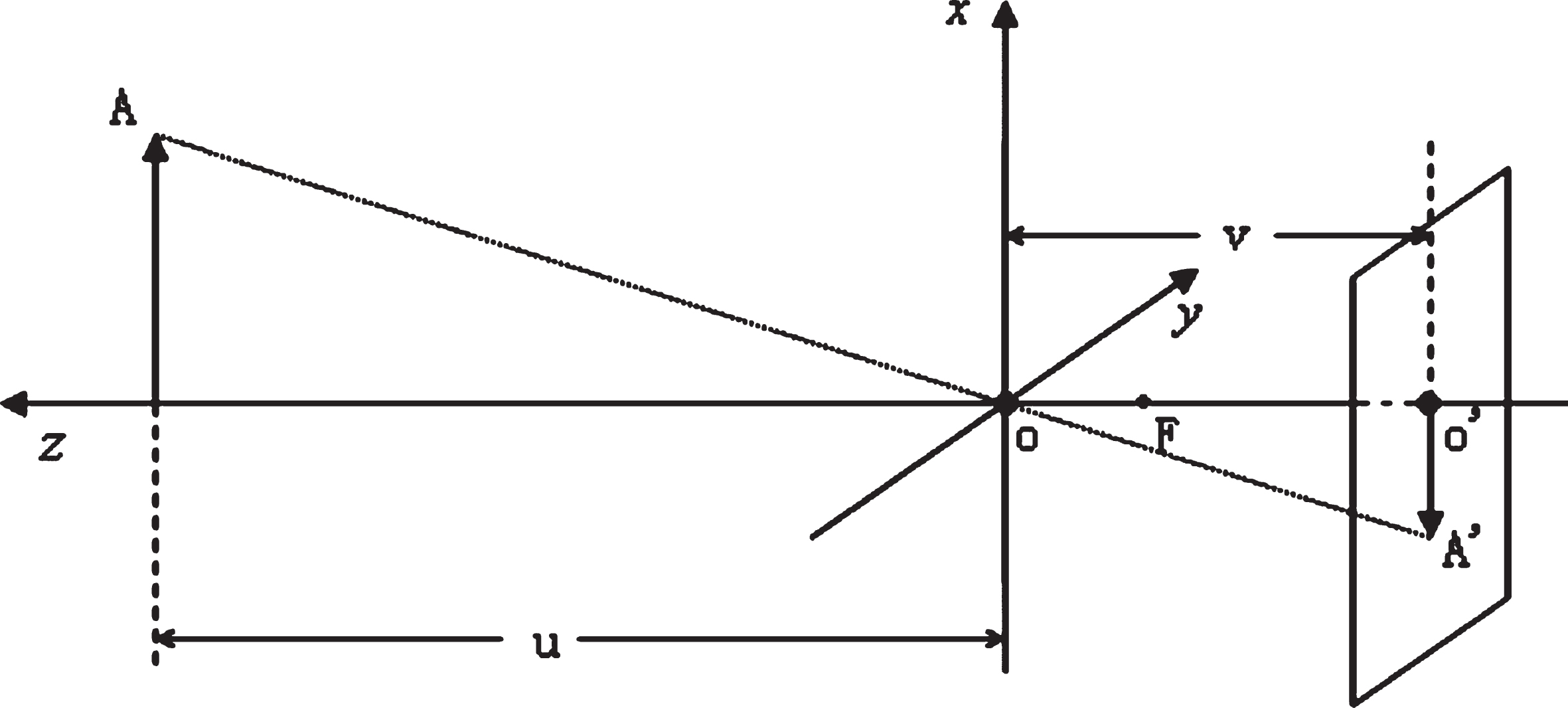
Camera imaging model.
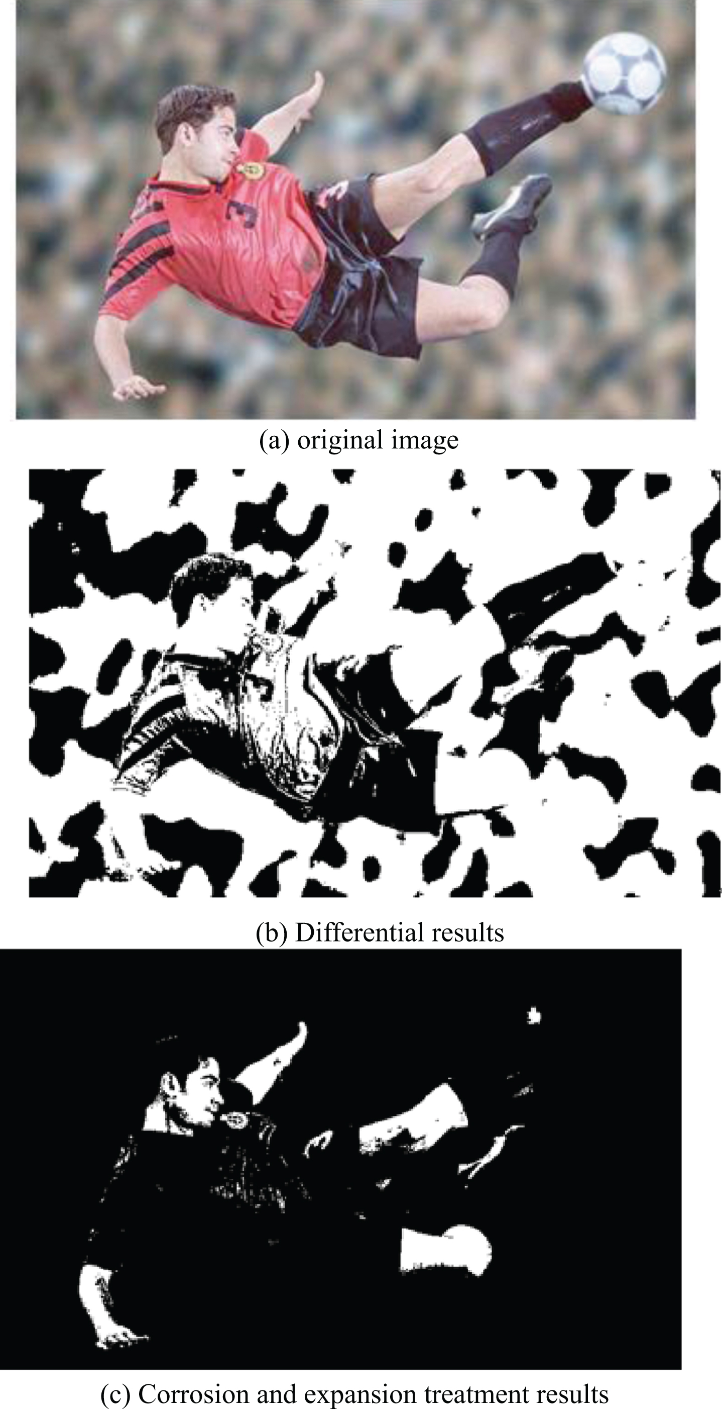
Human contour results extracted from human motion image sequences.
The monocular vision three-dimensional human body pose estimation method based on the orthogonal proportional projection model is that the two-dimensional coordinates of the joint points of the skeleton, the length information of the skeleton segments (in units of pixels) and the constraint relationship on each bone segment are known. The two-dimensional coordinates of the joint point in the image can be obtained by the above algorithm, and the length information of the limb segment can be directly obtained by calculating the distance of these joint points. Their constraint relationship is constrained by a set of joint point depth inequalities, which aims to eliminate deep ambiguity problems. Finally, a three-dimensional joint skeleton attitude model can be given from any angle. Figure 9 shows the motion recovery results of selecting several frames from more than 300 frames of indoor and outdoor video sequences.

Human skeleton root node.

Test results.

Statistics image of the number of different feature points in the skeletonization process.
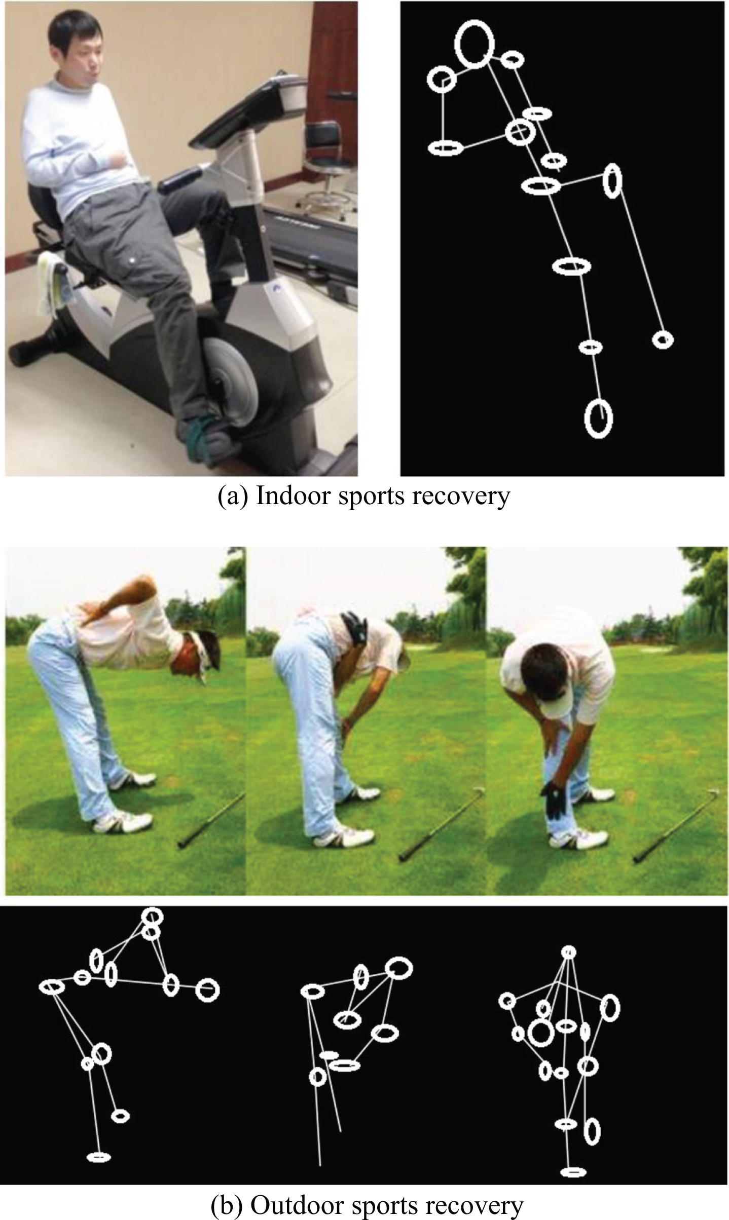
Human motion recovery results under monocular video.
Figure 9 shows the partial recovery results in the first 180 frames. It can be seen that the overall motion posture after recovery is close to the actual human posture in the video, but there is also a certain deviation. It is caused by the cumulative error and illumination changes tracked by the kalman filter. In the experiment of the algorithm of this paper, after the frame number is more than 150 frames, the tracking error is obvious, and the recovery result of the virtual skeleton upper limb is greatly deviated from the actual image posture. The closer the joint is to the root joint, the smaller the error after recovery, and vice versa. Obviously, the recovery error of the arm joint is greater than the recovery error of the upper arm. This is because the recovery structure of the child joint is affected by the restoration of the parent joint. For example, in the “lifting leg” action in the experimental result, the error of the calf recovery result is slightly larger.
The scale factor used by the Taylor algorithm is calculated by fixing the height of the human body model to the height ratio of the human body in the image, and the accuracy of the algorithm is affected by different proportions of the human body. Moreover, to a large extent, the accuracy of the algorithm also depends on the scale factor S. When the S value is larger, the human body posture has a tendency to be “stretched” along the optical axis direction of the camera. This chapter uses the non-fixed human skeleton model to estimate the scale of the model in two-dimensional space, and solves it based on the proportional orthogonal projection model and the inherent constraint relationship of the human body, which eliminates the depth ambiguity between the joint points in the three-dimensional recovery process to some extent. The recovery accuracy of the algorithm is determined by several factors, including the initial estimation of the two-dimensional coordinates of the joint point, the accuracy of the estimation, and the proportional length of each bone segment in the human skeleton model.
This study is based on monocular vision and monitors the athlete’s movement process, and on this basis, develops corresponding recovery techniques. At the same time, this paper analyzes the imaging principle and distortion principle of the camera, adjusts the pixel coordinates of the acquired target point, and improves the positioning accuracy of the monocular vision system. The skeleton extraction method proposed in this study is based on the contour of the human body, and the human binary contour image is extracted from the sequence image to be processed. Usually, the moving body part is extracted from the background by using the motion information, and the binary contour image of the human body is obtained through mathematical morphology operation. The experimental results show that the algorithm is simplified by a series of feature extractions, and the linear skeleton of the human body is completely extracted. Moreover, the entire skeleton has good connectivity, the position of the skeleton points is relatively accurate, and the topology of the original object is maintained. In addition, this study proposes a method for automatically extracting the linear skeleton of the human body under the condition of frontal movement of the human body and estimates the position of the main joint points of the skeleton by using the proportional relationship of the bones of the human physiological characteristics. The experimental results show that the proposed algorithm can effectively extract the skeleton structure and joint points of different human postures without occlusion and has strong robustness.
Footnotes
Acknowledgments
Innovation and design of college physical education teaching based on core quality of physical education (Grant No. 179).