
Abstract
This paper studies a hybrid power system composed of fuel cells, super capacitors and batteries. Super capacitors are used as auxiliary energy sources to provide the required high power when the car starts and accelerate, while absorbing braking energy when the car is braking. Fuzzy control is used to optimize its energy management strategy. The fuzzy controller of the three-energy source system takes the battery, super capacitor, and bus demand power as the input of the fuzzy controller, and the battery demand power and the fuel cell demand power as the fuzzy controller output. The system realizes the energy distribution of super capacitors, fuel cells and storage batteries according to power requirements, thereby improving the performance of the system and extending the life of components. And with hydrogen consumption as the optimization goal, the particle swarm algorithm is used to optimize the parameters of the fuzzy membership function. Compared with the fuzzy control strategy without particle swarm optimization, the optimized fuzzy energy management strategy reduces the hydrogen consumption of fuel cell vehicles. 10 L/(100 km)-1, which improves the economy of the vehicle.
Keywords
Introduction
The power system is the core part of fuel cell vehicles, and it is also an important symbol that distinguishes it from traditional cars and other vehicles. At present, the existing and relatively mature fuel cell power system forms are mainly two types: a single fuel cell drive form and a hybrid drive form of a fuel cell plus an auxiliary energy source.
In a pure fuel cell power system, only the fuel cell system bears all the load power of the car during operation. Because only the fuel cell is used as the power source, the performance characteristics of the fuel cell directly determine the performance of the vehicle: (1) Due to the weak output characteristics of the fuel cell system, it is easy to cause poor dynamic response and cannot meet the driving power required by the car, so the vehicle power is poor; (2) Due to the unidirectional output of the fuel cell Characteristics, the vehicle cannot realize the recovery of regenerative braking energy; (3) As a single power source, the fuel cell system generally requires a large output power, which makes this type of vehicle mass and cost higher. (4) Under low temperature conditions, it is affected by the cold start characteristics of the fuel cell, so the cold start performance of the vehicle is poor.
Due to the above problems, the development of pure fuel cell vehicles is greatly restricted. However, based on the research done on this single fuel cell drive system, people have found that vehicles need to be equipped with some auxiliary energy sources to meet their needs. Therefore, a three-energy hybrid power scheme has emerged, that is, a multi-energy system composed of a fuel cell engine, a power battery and an on-board super capacitor. The structure diagram of fuel cell vehicle powertrain is shown in Fig. 1. Compared with the traditional fuel cell engine+power battery (FCE+BP) or fuel cell+super capacitor (FCE+UC) two hybrid solutions, the three-energy hybrid power system maintains the advantage that the power battery can store a large amount of energy for a long time, The super capacitor system is used to meet the requirements of peak power and emergency power, and also participates in absorbing the braking feedback energy of the car; due to the high power density of the super capacitor, the high charging and discharging efficiency, and the ability to accept large current fast charging, It can well protect the battery pack to prevent overcharging, and can effectively improve the braking feedback performance, so as to improve the overall efficiency and life of the power system. The current research mainly has the following three problems [1–4]: In the three-energy source system, energy does not flow in a single path, and there are multiple power split modes between each energy source. Therefore, in the process of power system design and matching, it is necessary to consider not only the power index requirements and the characteristics of urban road conditions, but also the working mode and switching conditions of the three-energy source system should also be integrated. At present, there are few researches on the parameter design of the three-energy source system, and more extensive matching methods based on dynamic indicators are used. Therefore, the matching results of the components of the power system have great redundancy, which is not conducive to reducing the cost of the vehicle and increasing the vehicle. Economy. The energy management strategy directly affects the performance of the whole vehicle. The strategy needs to realize the coordinated control between the three energy sources. It is necessary to give full play to the advantages of the three-energy source system, but also to consider the efficiency and economy of the strategy. The current research on the energy management strategy of the three-energy source system mostly focuses on the rule-based control method and the most economical control method. The rule-based control method is simple in logic, but it is difficult to achieve optimal economic efficiency; the control method based on optimal economic efficiency can give full play to the advantages of the three-energy source system and achieve the lowest energy loss, but the algorithm complexity is high, and it is difficult to actually install the vehicle. The optimization of the three-energy source system can modify the design parameters and control parameters, and improve the rationality of the system design. The current three-energy source system optimization mostly uses a single optimization method, that is, individually optimizing design parameters or control parameters to achieve optimal design matching or optimal energy distribution. However, the design parameters and control parameters in this system are not purely linear. There is a deep coupling between the two. It is difficult for a single optimization method to achieve global optimization. Therefore, it is urgent to design a composite optimization method that comprehensively considers the two types of parameter strong coupling conditions.

Structure diagram of fuel cell vehicle powertrain.
In this study, the proton exchange membrane fuel cell was selected as the main power source of the vehicle. Compared with other fuel cells, the working environment of the proton exchange membrane fuel cell is lower. It uses hydrogen as the fuel, air or pure oxygen as the oxidant, and generally uses platinum as the catalyst. For proton exchange membrane fuel cells, fuel supply and circulation systems, oxidizer supply systems, power generation systems, water/heat management systems, power systems, safety systems, and control systems are required [5, 6]. Figure 2 displays the energy conversion path.
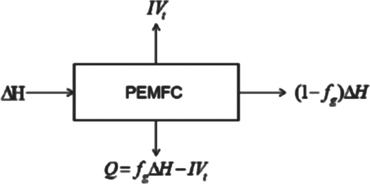
Energy conversion path of fuel cell.
ΔH: The overall enthalpy of the fuel cell.
IV t : External output.
f g : Utilization rate of hydrogen and oxygen.
Q: The heat transferred between the fuel cell and the environment.
f
fc
: The ratio of the energy output by the fuel cell to the total enthalpy of the fuel.
Can also be expressed as:
fT =
fV =
It: Fuel cell output power
fl =
fFC: Fuel cell efficiency
In order to have a clearer understanding of fuel cell output characteristics, explore the changes in fuel cell output performance under different temperature and humidity conditions, and independently build and test fuel cell test benches. The parameters are given in Table 1. By changing the external load of the fuel cell to simulate the application of the fuel cell in the whole vehicle, and studying its influence on the fuel cell, the polarization curve and efficiency curve of the fuel cell are finally obtained. As shown in Figs. 3 and 4.
The selected fuel cell module parameters

Fuel cell efficiency curve.
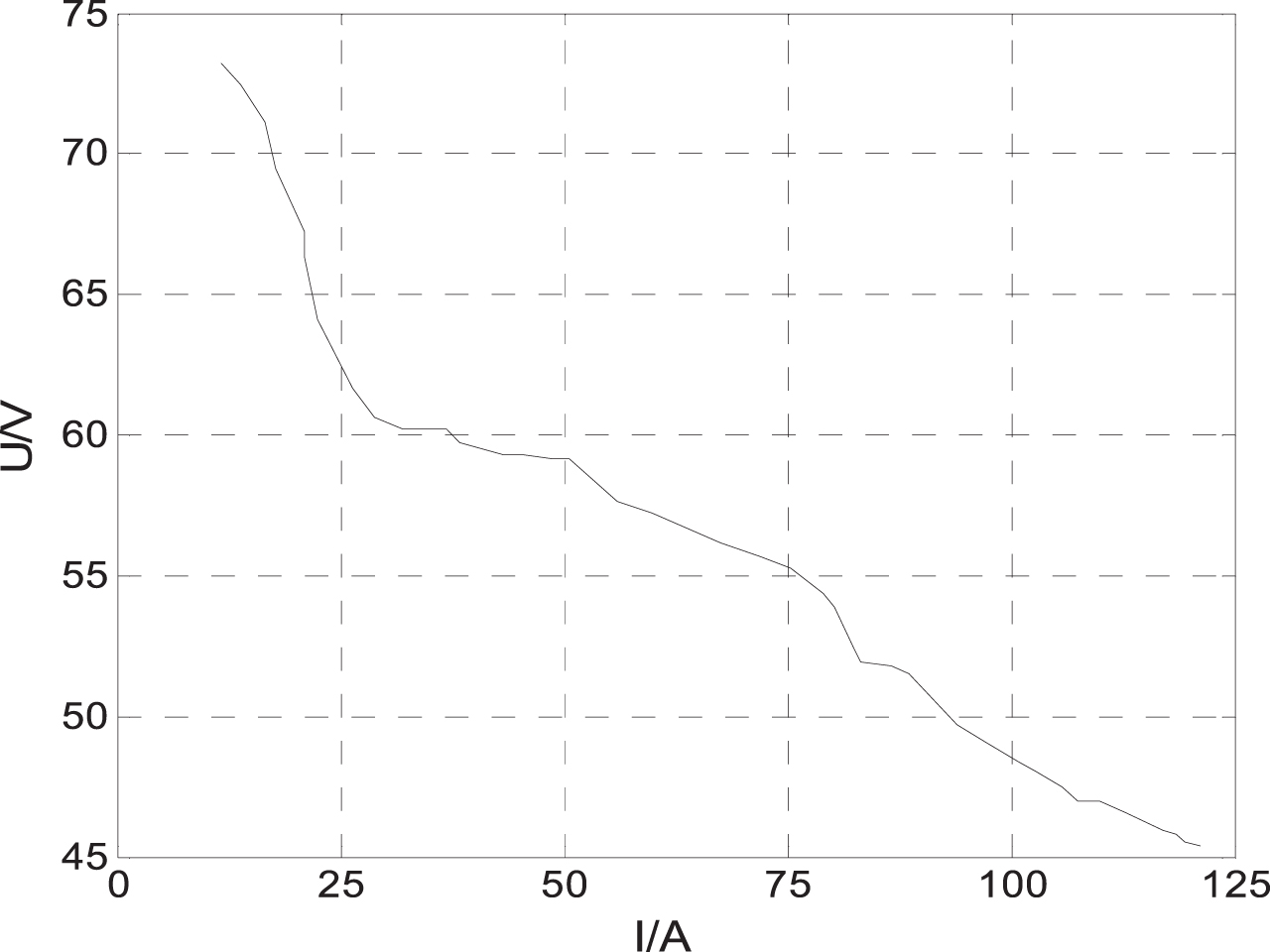
Polarization curve of fuel cell.
In the light load stage, the voltage is the largest and the efficiency is the highest. With the current loading, the voltage and electrical efficiency will drop significantly in the initial stage due to the influence of activation polarization. In the process of slowly increasing the current, the voltage tends to be stable and the efficiency tends to be stable.
It can be seen from the Fig. 5 that, at different temperatures, the overall fuel cell polarization curve does not change significantly, but the voltage is significantly different. As the temperature increases, the output of the fuel cell increases. When the temperature is greater than 70 ¡æ, its voltage value drops in the latter half, so the fuel cell will have an optimal operating temperature.

Fuel cell polarization curve at different temperatures.
The capacitor energy storage formula can be expressed as:
It can be seen that when the capacitor is charged to a certain voltage value, the stored energy can be calculated. At the rated voltage, the super capacitor can store the maximum energy. Ucmin and Ucmax are the open circuit voltage of the capacitor after discharge and when it is fully charged, the super capacitor SOCc can be expressed as:
Charging Ic < 0
Discharge operation Ic > 0
Uoc: Open circuit voltage
Uc: Terminal voltage
Ic: Charge and discharge current
Rc: Super capacitor equivalent internal resistance.
C: Capacitance
UN: Rated voltage
IN: Rated current
Re: Equivalent internal resistance
IL: Leakage current
The energy loss in the capacitor mainly comes from the series resistance, and the terminal voltage is too low or the discharge current is too large, which will reduce the working efficiency of the capacitor. Therefore, in the system, it is necessary to make the capacitor work within a reasonable range of voltage. Compared with batteries, although supercapacitors have lower specific energy, they have much higher specific power, and are suitable for high current discharge to provide load peak power. The parameters of super capacitor monomer are shown in Table 2.
Super capacitor monomer parameters
Supercapacitors are more suitable for auxiliary power supplies. As shown in Fig. 6, under different constant discharge current conditions, as the discharge current increases, the voltage at the supercapacitor terminal drops faster than the battery, and the discharge duration is shorter. In addition, when the vehicle is frequently started, stopped and accelerated, the super capacitor is quickly consumed when the high current is discharged, and the performance of the composite power system cannot be exerted. At this time, the battery charges the super capacitor.
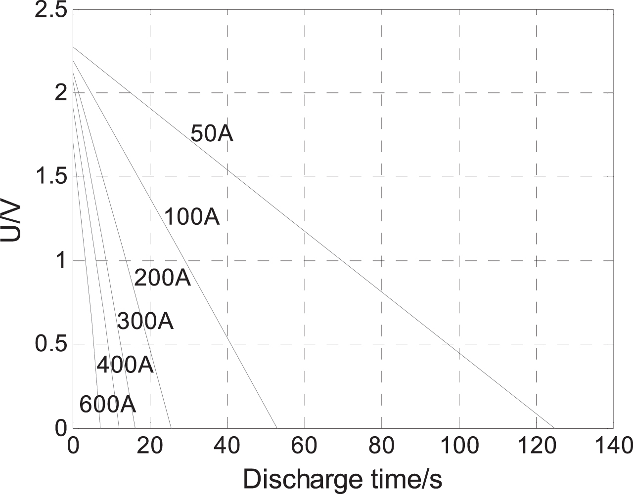
Discharging characteristic curve.
As shown in Fig. 7, at the beginning of charging, under constant different charging current conditions, the greater the charging current, the greater the voltage jump at the capacitor cell terminal and the shorter the charging time. When the charging current is constant, the terminal voltage of the super capacitor is linearly related to the charging time, indicating that the energy storage efficiency of the super capacitor is much higher than that of the battery. It has a strong large current absorption energy and is suitable as an energy feedback device during regenerative braking [7].

Charging characteristic curve.
Battery modeling
Uoc, U: Battery open circuit voltage, circuit terminal voltage.
R0, R1, R2: The ohmic internal resistance of the battery, the resistance caused by charge transfer, the resistance caused by charge diffusion.
C1, C2: Capacitance caused by charge transfer, capacitance caused by charge diffusion.
C1, R1: The short time constant of the battery dynamic response process.
C2, R2: The long time constant of the battery dynamic response process.
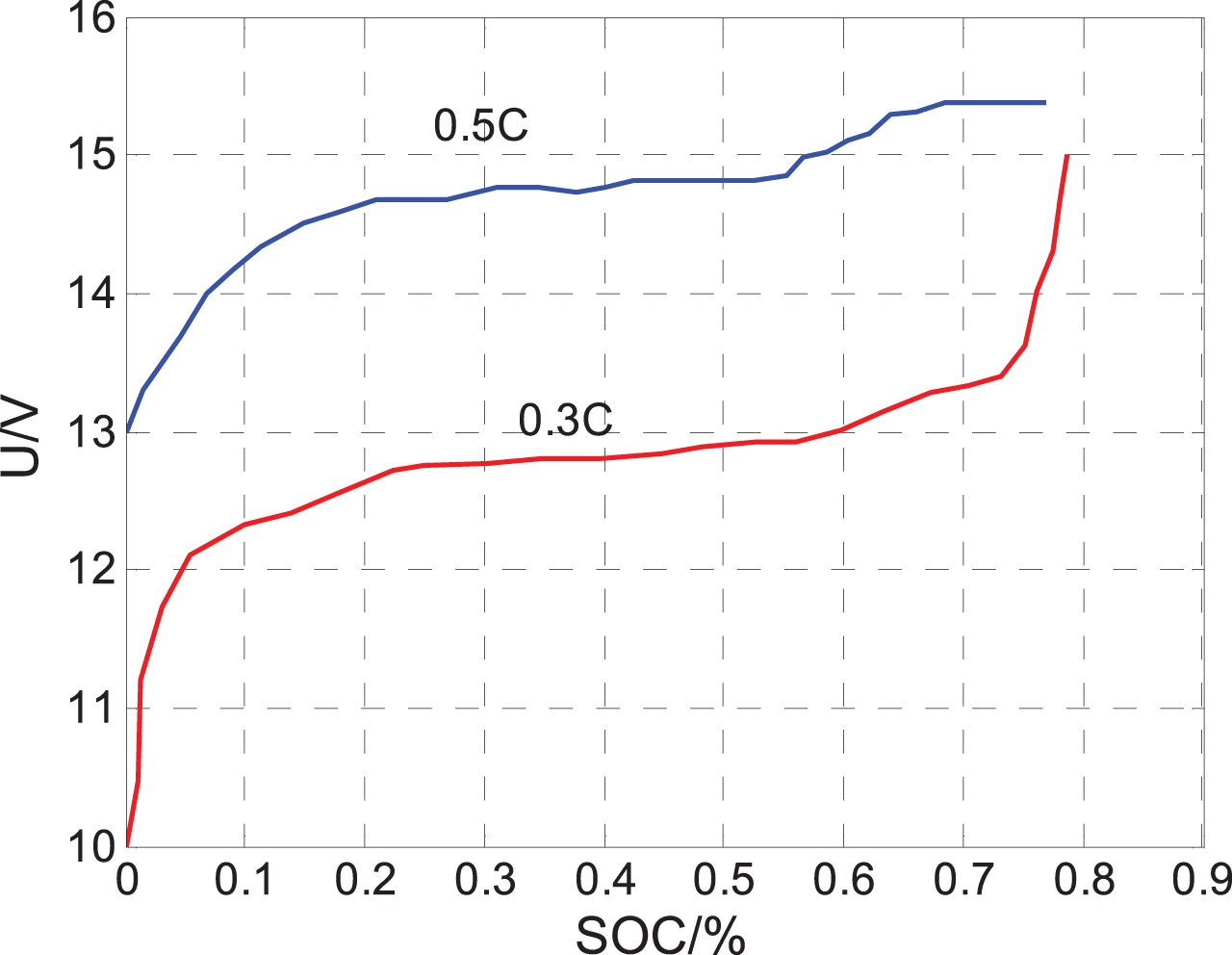
Electromotive force (EMF) is a very important parameter for power batteries. In calculations such as battery SOC numerical estimation, equivalent circuit model related parameter calculation, and battery equivalent model verification, it is necessary to determine the battery EMF, usually based on the battery’s open circuit voltage (OCV) is equivalent to replace the battery EMF, and the SOC value of the battery at the moment is estimated by the size of the battery OCV value. Figure 8 shows the battery principle model. At room temperature, a power lithium-ion battery with a model specification of 10AH/12 V was used as the experimental object, and constant current discharge and constant current charging experiments were carried out at 0.2 C and 0.5 C respectively. As shown in Figs. 9 and 10. The lithium battery monomer parameters are shown in Table 3. Initial discharge stage: The voltage of the lithium-ion battery terminal has a rapid decline process, the greater the discharge current, the greater the voltage drop; When the battery SOC is in the range of about 20% to 70%, it is called the platform voltage stage: in this interval, the battery voltage drops very slowly. When the battery is in the platform voltage area, the battery terminal voltage changes very little. This is also the main reason why it is difficult to accurately estimate the status of lithium-ion batteries. The smaller the discharge current, the higher the platform voltage, and the slower the voltage drop; End of battery discharge: In the late stage of battery constant current discharge, after the platform voltage stage ends, the battery terminal voltage drops rapidly until it reaches the discharge cut-off voltage.

Battery principle model.
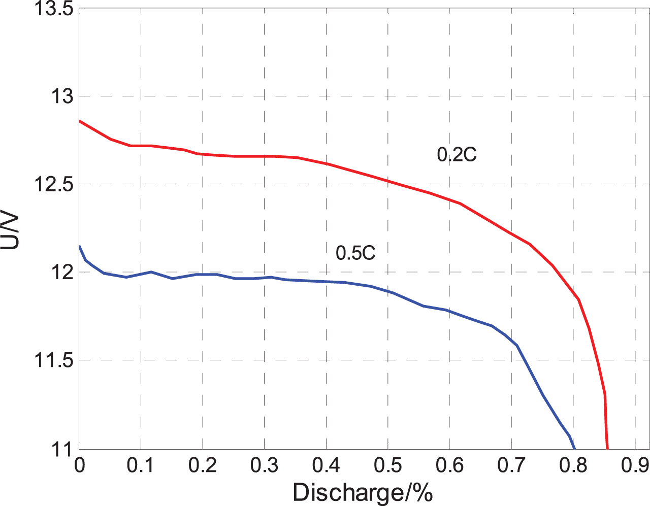
Discharging characteristic curve.
Charging characteristic curve.
The lithium battery monomer parameters
Initial charging stage: In this stage, the terminal voltage of the lithium-ion battery is a rapid increase process, and the greater the charging current, the greater the voltage increase. Similar to the discharge process, when the SOC is within the range of 20% to 70%, the battery charging stage also has a platform voltage stage: from the charging curve, it can be seen that the greater the charging current, the higher the corresponding platform voltage. The end of battery charging: When the battery terminal voltage reaches the maximum value, the battery terminal voltage begins to decrease during the subsequent charging process. This is because when the voltage reaches the maximum value, the charging current is used to decompose the electrolyte solvent in the subsequent work project, which causes the terminal voltage to drop and the battery temperature rise. Therefore, the two phenomena of battery terminal voltage drop and battery temperature rise are used as conditions for judging whether the battery charging is terminated.
The main purpose of energy distribution is to improve the overall efficiency of the multi-energy system, thereby reducing the energy consumption of the system. Vehicles have three energy sources, and there is a complex coupling relationship between them. Therefore, the rationalization and efficiency of energy management strategies are crucial in the vehicle control architecture [8–10].
This method can greatly simplify the energy management architecture of the three-energy source vehicle and realize the high efficiency of the energy management strategy. Then, starting from the dynamic characteristics of each energy source, the power output characteristics of fuel cells, batteries, and super capacitors are further studied to complete Independent control of each energy source, this method can realize the coordinated control of the three energy sources to optimize the economy of the whole vehicle.
The three-energy source system of a hybrid fuel cell bus has the characteristics of strong coupling and nonlinearity. Therefore, establishing its precise control strategy model based on mathematical logic rules will not only increase the strategy complexity, but also reduce the robustness of the model. The fuzzy control has the advantages of low dependence on the model, simple control rule establishment process, ideal control effect, etc. Therefore, this section is based on the fuzzy control method to extract the power split control rules of the three-energy source system to realize the energy of the hybrid fuel cell bus. management. The vehicle parameters are shown in Table 4.
The vehicle parameters
The vehicle parameters
The fuel cell and battery hybrid drive type is currently a more commonly used drive structure. This structure adds an auxiliary battery and a unidirectional direct current/direct current (DC/DC) converter on the basis of the fuel cell drive structure, as shown in the following Fig. 11 Show.
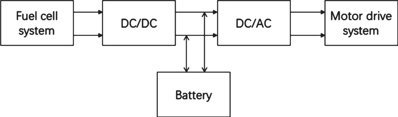
FC+B drive structure of hybrid vehicle.
In this drive structure, the fuel cell serves as the main power source to provide continuous power. When the required power is too large, the battery provides supplementary energy to play an auxiliary role; when the vehicle is braking, the battery recovers part of the braking energy. In addition, the auxiliary battery can meet some special needs of the fuel cell system itself, such as powering the air compressor or blower when starting, humidifying the hydrogen and air, and heating the stack [11–14].
In the starting condition, it is generally driven by the battery alone. When the fuel cell reaches the starting temperature, it is determined whether to start the fuel cell according to the power demand and the battery SOC; (2) If the battery SOC value is lower than the expected value and the operating condition requires power at the fuel cell location Between the maximum output power and the minimum output power that can be provided, the fuel cell output power meets the requirements of working conditions and charges the battery at the same time. (3) The fuel cell and battery combined drive mode. When the power required by the working condition is greater than the maximum output power that the fuel cell can provide, the fuel cell provides the maximum power to the outside, and the remaining power is provided by the battery. (4) In the regenerative braking mode, when the vehicle decelerates or brakes, the motor enters the power generation mode, the battery recovers energy, and the fuel cell stops working.
In the design of the fuzzy controller, the required power of the electric motor and the SOC of the battery are fuzzy processed, and the required power of the electric motor is allocated to the fuel cell system and the battery more reasonably. The input variables of the fuzzy controller are the motor demand power Pm and the battery SOC value, and the output variables are the fuel cell system’s required power Pfc. The fuzzy domain of motor demand power Pm is [–1,1], the fuzzy subset is {FG,FZ,FD,PD,PZ,PG}, the fuzzy domain of battery SOC value is [0,1], the fuzzy subset Divided into {D,Z,G}, the fuel cell needs to provide power Pfc fuzzy domain is [0,1], the fuzzy subset is divided into {NG, NZ, ND, HD, HZ, HG}.
18 fuzzy control rules are formulated for the controlled variables, as shown in Table 5. All control rules are summarized based on actual operating experience. In this paper, the Mamdani reasoning method is used for fuzzy relation reasoning. After fuzzy reasoning, the weighted average method (gravity method) is used to de-fuzzify.
Fuzzy rule table
The vehicle speed-time curve, SOC change curve, fuel cell power-time curve, and power battery power-time curve are obtained, as shown in Figs. 12, 13 and 14. When the power battery works under normal conditions, the SOC will fluctuate within a certain range, generally in a relatively stable range, set SOC = 0.5, and the power battery SOC value is within the range of the maximum and minimum values. The fuel cell provides a maximum power of 50 kW, and the battery takes on a small part of the power. The positive power is the output power, and the negative power is the power used to charge the lithium battery when the fuel cell or braking energy is fed back. Under the braking energy recovery and the fuel cell output balance power Steadily increase to meet the power requirements of the vehicle. The output power of the fuel cell system can meet most of the relatively flat power demand, but cannot follow some instantaneous high-power demand. At this time, the battery should respond quickly and cooperate with the fuel cell system to meet the load demand power. When the load demand power is less than the minimum output power Pfcmin of the fuel cell, in order to prevent the fuel cell from working in a low efficiency area, it should be operated at the minimum output power, and the battery recovers the remaining energy. When the load demand power is large, it can avoid the instantaneous high-current discharge and long-time high-power operation of the fuel cell, and at the same time make the fuel cell work in a higher efficiency range, and the battery supplements the main power source to better meet the acceleration requirements of driving conditions; When the car is decelerating, the load power is negative, and the absolute value of the load power is greater than the maximum charging power of the battery. At this time, the charging power is limited so that it is not greater than the maximum charging power of the battery.
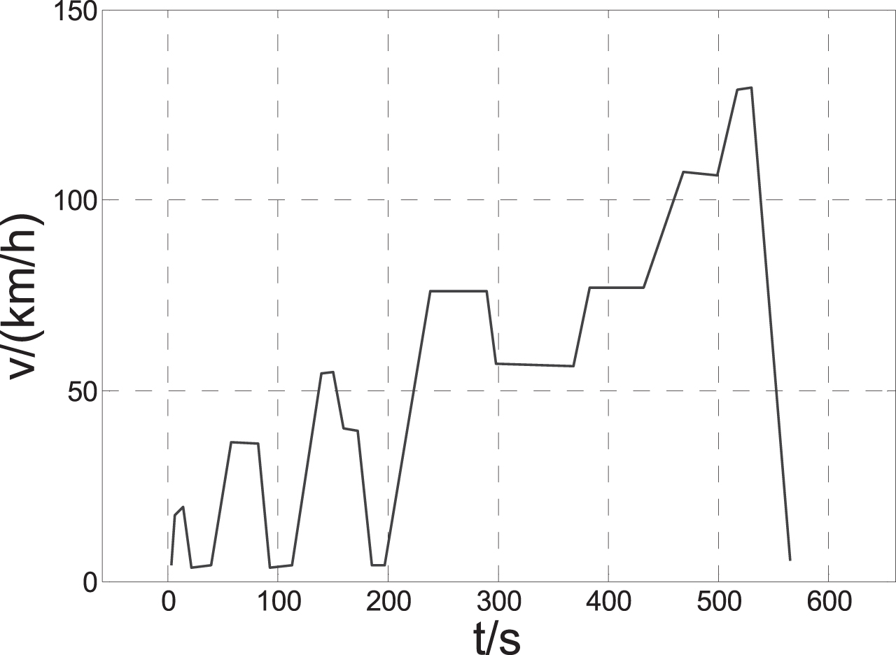
Vehicle speed in NEDC cycle.
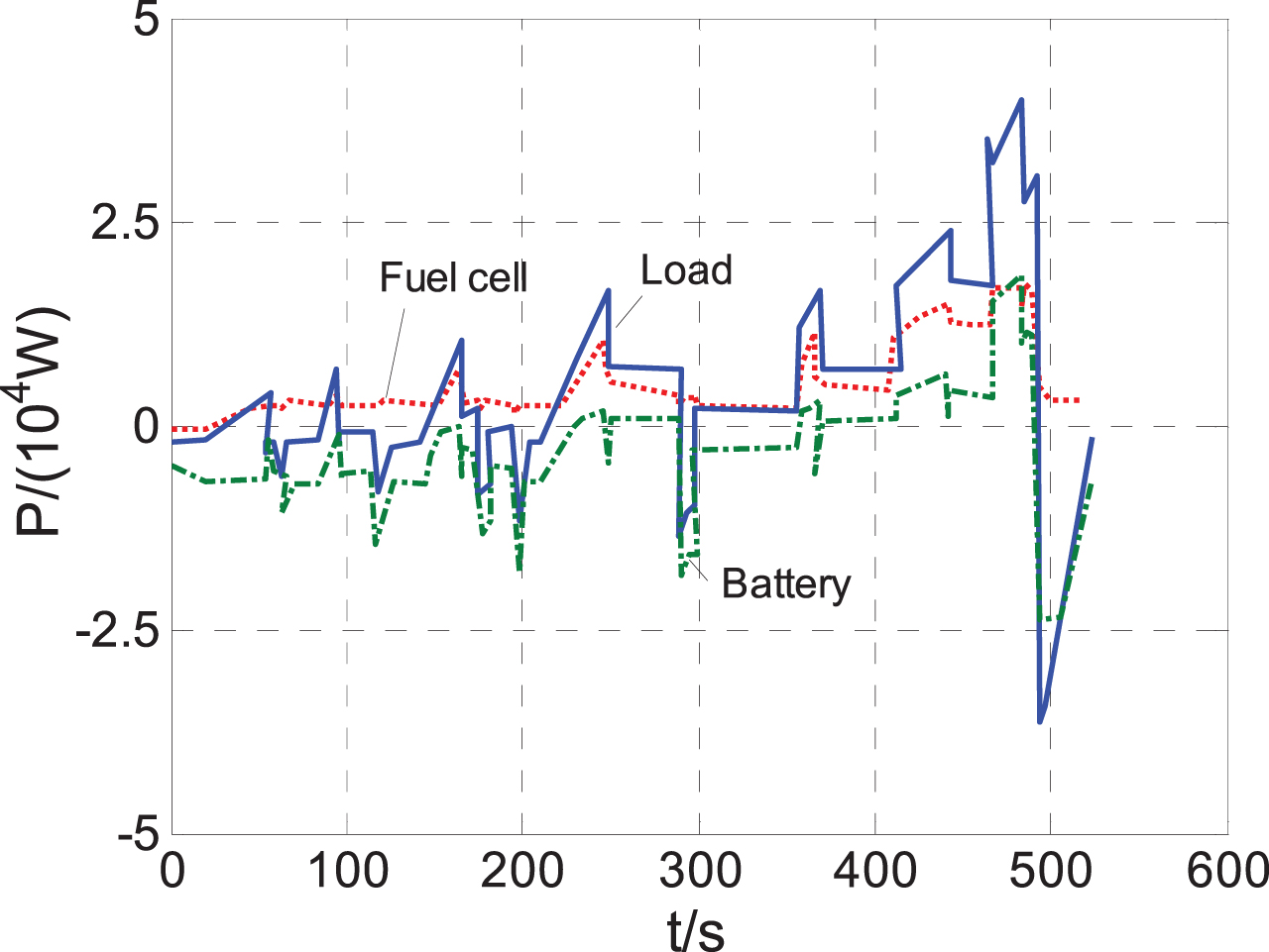
Power curve with initial Hsoc = 0.6.

SOC curve.
In the process of designing a fuzzy controller, the more input variables, the more ideal the output result of fuzzy inference, but at the same time it will lead to the increase of computational complexity. Considering the accuracy of the output result and the complexity of fuzzy inference, the fuzzy controller of the three-energy source system takes the battery SOCbat, super capacitor SOCsc, and bus demand power Preq as the fuzzy controller input, the battery demand power Pbat and the fuel cell demand power Pfc are output as the fuzzy controller.
In the drive mode, Preq > 0, in order to simplify the design process of the controller, set the domains of SOCbat, SOCsc, and Preq to [0,1]. At this time, the corresponding quantization factors of SOCbat and SOCsc are set to 1, the quantization factor of Preq is set to the reciprocal of its maximum value Pmax, namely 1/Pmax.
Considering the large battery capacity value, from the perspective of the accuracy of the fuzzy controller, set the fuzzy subset of SOCbat as {XL, L, M, H, XH}, where XL, L, M, H, XH are respectively Corresponds to very low, low, medium, high, and very high; set the fuzzy subset of SOCsc to {XL,L,M,H}, where XL, L, M, and H correspond to very low, low, medium, and high respectively; Preq has a large variation range, and there are many operating points where the bus demand power is zero in cyclic conditions, so the fuzzy subset is set to {XL, L, M, H, XH}, where XL, L, M, H, XH respectively correspond to very low, low, medium, high, and very high; the battery demand power Pbat has a large transformation range. From the perspective of accuracy, set its fuzzy subset to {XL, L, M, H, XH}, where XL, L, M, H, XH correspond to very low, low, medium, high, and high respectively. Fuel cells tend to output relatively stable power and should not have large power fluctuations. Therefore, the fuzzy subset of fuel cell demand power Pfc is set as {L, M, H}, where L, M, and H correspond to Low Medium High.
Because the SOC signal has higher sensitivity requirements, the membership functions of SOCbat and SOCsc are selected as triangles; and the power signal has higher requirements for stability, so the membership functions of Preq, Pbat, and Pfc are selected as trapezoid. After completing the selection of fuzzy subsets and membership functions, fuzzy rules need to be extracted. The design process of fuzzy rules needs to meet the following principles.
When Preq is zero, Pfc and Pbat are both zero; when Preq is small, the fuel cell provides most of the power at this time, and the battery and super capacitor supplement energy according to their own SOC; when the Preq is medium, the fuel cell should provide part of the power is maintained in the economically optimal working range, and the battery and super capacitor are supplemented according to their own SOC; when the Preq is high, the fuel cell, battery, and super capacitor should work together to meet the vehicle power demand as the primary goal.
The simulation is performed under NEDC operating conditions, and the vehicle operating conditions follow well. The change curves of SOCbat and SOCsc are as shown in the Figs. 15 and 16. The change of SOCbat is gentle, showing a downward trend in the whole cycle, which is in line with its own working characteristics; SOCsc has relatively large changes and has good power regulation capabilities, and the overall trend is increasing. Realize the function of “peak cutting and filling valley”.
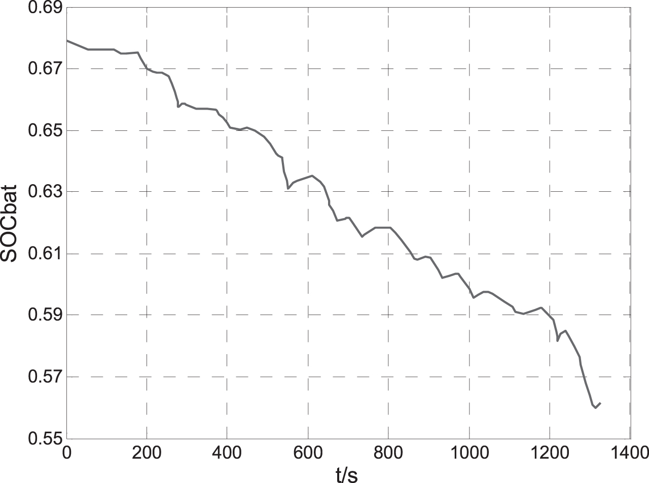
SOCbat characteristic curve.

SOCsc characteristic curve.
The power split curve under the three-energy source energy management strategy based on fuzzy logic is shown in the Fig. 17. Under NEDC operating conditions, the sum of the required power of each energy source is the bus demand power. The fuel cell has no negative power demand, and the demand power does not exceed its own maximum power. In the driving mode, since the output of the fuzzy controller defined in the strategy is the ratio of the power split between the fuel cell and the battery, the super capacitor is mainly used for power compensation, so its required power is relatively small.

Three energy source power split curves.
The formulation of the membership function and rules of fuzzy control mainly relies on the experience of experts, and lacks the direction and target of fixed value and quantitative control. Therefore, when using fuzzy control to solve a problem, it often falls into a local optimal situation. As a global optimization algorithm, particle swarm has the advantages of easy implementation, high precision and fast convergence. This paper combines particle swarm algorithm and fuzzy control algorithm to formulate energy management strategy for dual-source hybrid power system.
Particle swarm algorithm
Particle swarm algorithm is an evolutionary algorithm based on swarms, and its basic idea comes from the research and behavior simulation of the simplified social model of bird swarms. When the particle swarm algorithm is used to solve the optimization problem, the potential solution of the problem is called a particle in the search space. Each particle has its own position and velocity, and fitness value determined by the optimized problem. The basic particle swarm algorithm corrects individual behaviors through information sharing between groups and individual experience summaries, and finally finds a solution to the optimization problem.
The algorithm first initializes to generate a group of random particles, and then iteratively finds the optimal solution. In each iteration, the particle keeps updating itself by tracking two extreme values: one is the optimal solution found by the particle itself, called the individual extreme value pBest, the other is the optimal solution found so far for the entire population, called the global extremum gBest, and then update the speed and position according to the following formula. There are four pieces of information for each particle to change its current position, namely: the current position of the particle, the current speed, the distance between the current position and the best position of the particle, and the distance between the current position and the best position of the group. The ultimate goal is that the particles converge to the global optimal value.
Particle swarm optimization algorithm design
There are three main points of particle swarm optimization fuzzy control, which are the selection of particle swarm optimization parameters, the determination of particle swarm objective function, and the co-simulation of particle swarm algorithm and dual-source hybrid power system based on MATLAB/Simulink embedded fuzzy control energy management strategy. Using particle swarm optimization to optimize the fuzzy controller is to adjust the parameters of the fuzzy controller. Fuzzy control membership function and fuzzy control rules are the parameters of fuzzy controller. The more parameters of the particle swarm optimization, the greater the possibility of obtaining the global optimal solution, but as the parameters increase, the greater the dimension of the particle. In order to obtain the global optimal solution, the size of the particle population and the number of iterations must be increased, which in turn leads to too long calculation and simulation time. In addition, it is difficult to establish correlation equations between fuzzy control rules, only relying on the combination of random particles to approximate the optimal solution, the optimization results will have some fuzzy control rules that cannot be explained by expert knowledge or are contradictory. In order to solve the above problems, this paper uses particle swarm algorithm to adjust the membership function parameters of the fuzzy controller [15, 16]. The membership function is shown in Fig. 18.
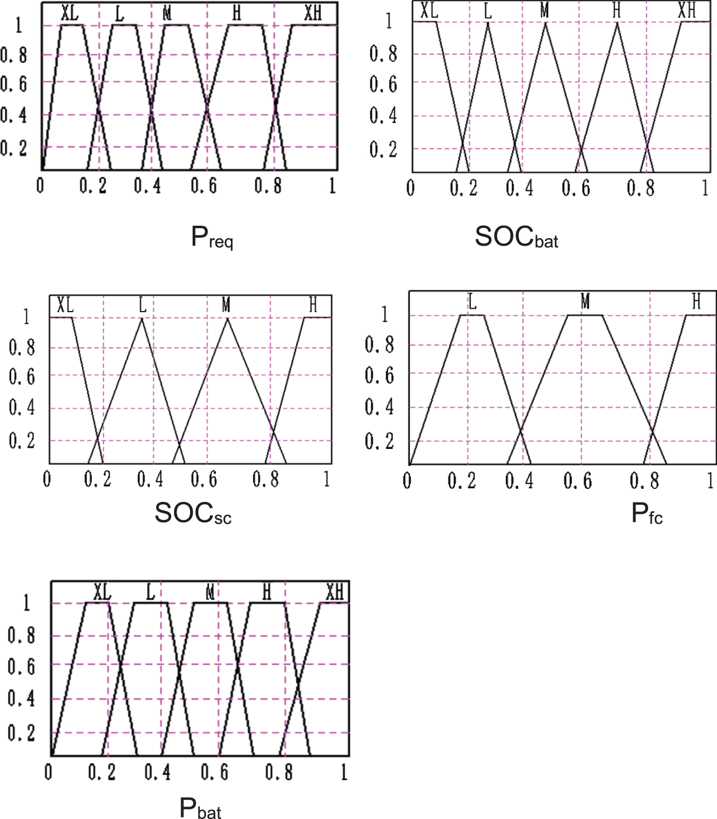
Original membership function.
The optimization goal of the fuel cell electric vehicle power system is to improve the fuel economy as much as possible on the basis of meeting the vehicle’s dynamic performance. The optimization goal can be expressed by the following formula:
X: Fuel cell electric vehicle power system parameters and vector of control parameters;
Ω: Possible solution space
Fuel(X): Fuel consumption
Tj(X) >0: Non-linear inequality constraints, automotive performance requirements and boundary value conditions of blending degrees, etc [17, 18].
When optimizing the design, in addition to reducing fuel consumption as much as possible, it must also meet the vehicle’s power performance requirements and power balance requirements. The optimization constraints are shown in Table 6.
The optimization constraints
In this paper, the dimension of the solution space of the particles is set to 10, the size of the particle swarm is 50, the number of iterations is 80, and the inertia weight factor decreases linearly between 1.5 and 0.5. The initial value of the position of the empirical particle is the blur before optimization described above. Control rule membership function parameter position code value. In the optimization process, the initial particle swarm is firstly generated, the particle parameters are assigned in turn, the fuzzy control membership function is obtained, and the energy control system is run, and a series of performance indicators are calculated. Based on this, it is judged whether the iteration condition is satisfied, and if the iteration condition is satisfied, the optimization at the end, if the optimization conditions are not met, the particle swarm is updated, and the above optimization process is repeated until an optimal solution that meets the iteration conditions is obtained. The particles basically converged to the optimal value of the objective function after 70 generations. The membership function of fuzzy control in this state is shown in the Fig. 19.
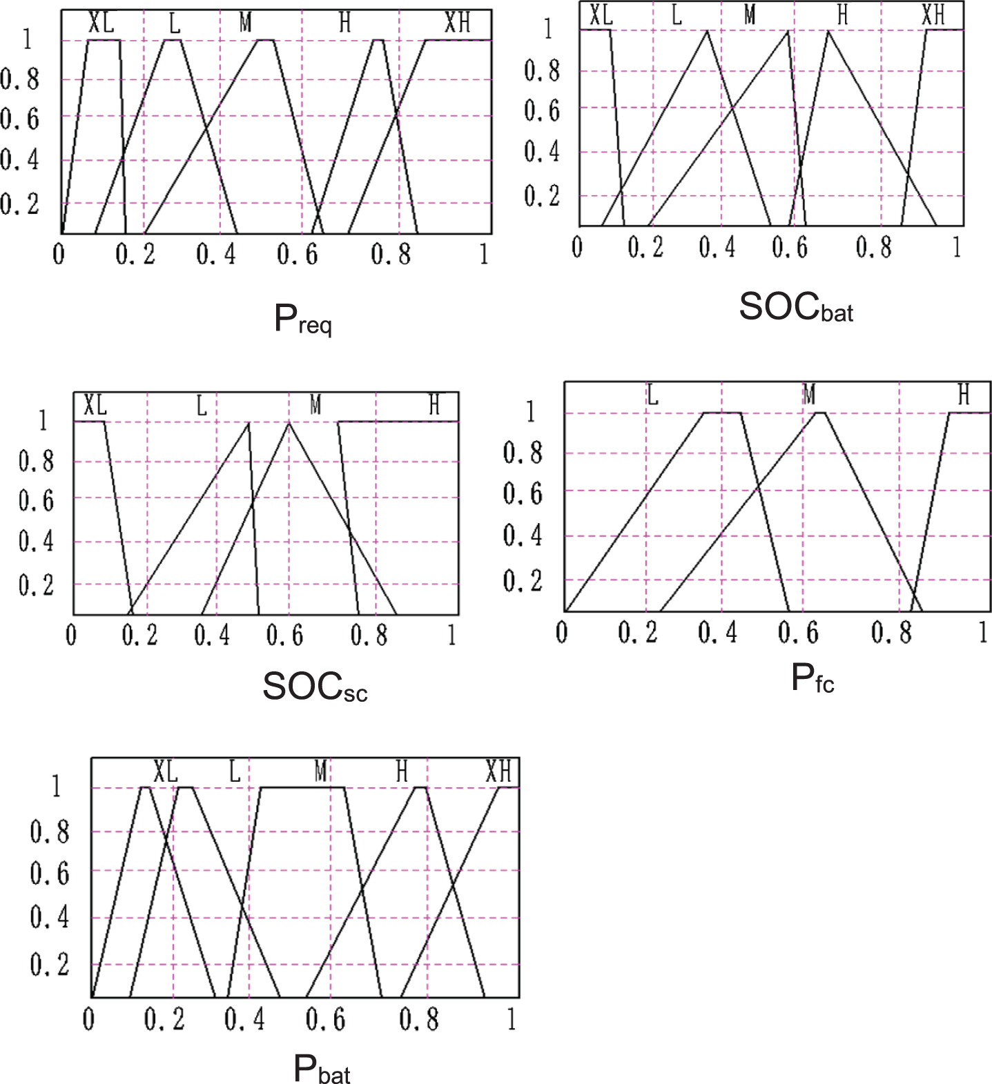
Optimized membership function.
It can be seen that the battery bears a small part of the low-frequency power, of which the positive power is the output power, and the negative power is the power to charge the battery when the fuel cell or braking energy is fed back. Most of the energy is provided by the fuel cell. The maximum power provided by the fuel cell is 50 kW. The positive power in the super capacitor output power graph indicates that the super capacitor provides energy, and the negative power indicates that the super capacitor absorbs fuel cell or brake feedback energy. As shown in Figs. 20, 21, 22.
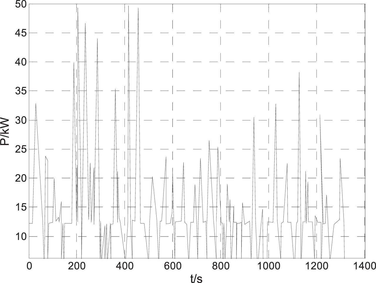
Fuel cell output power.
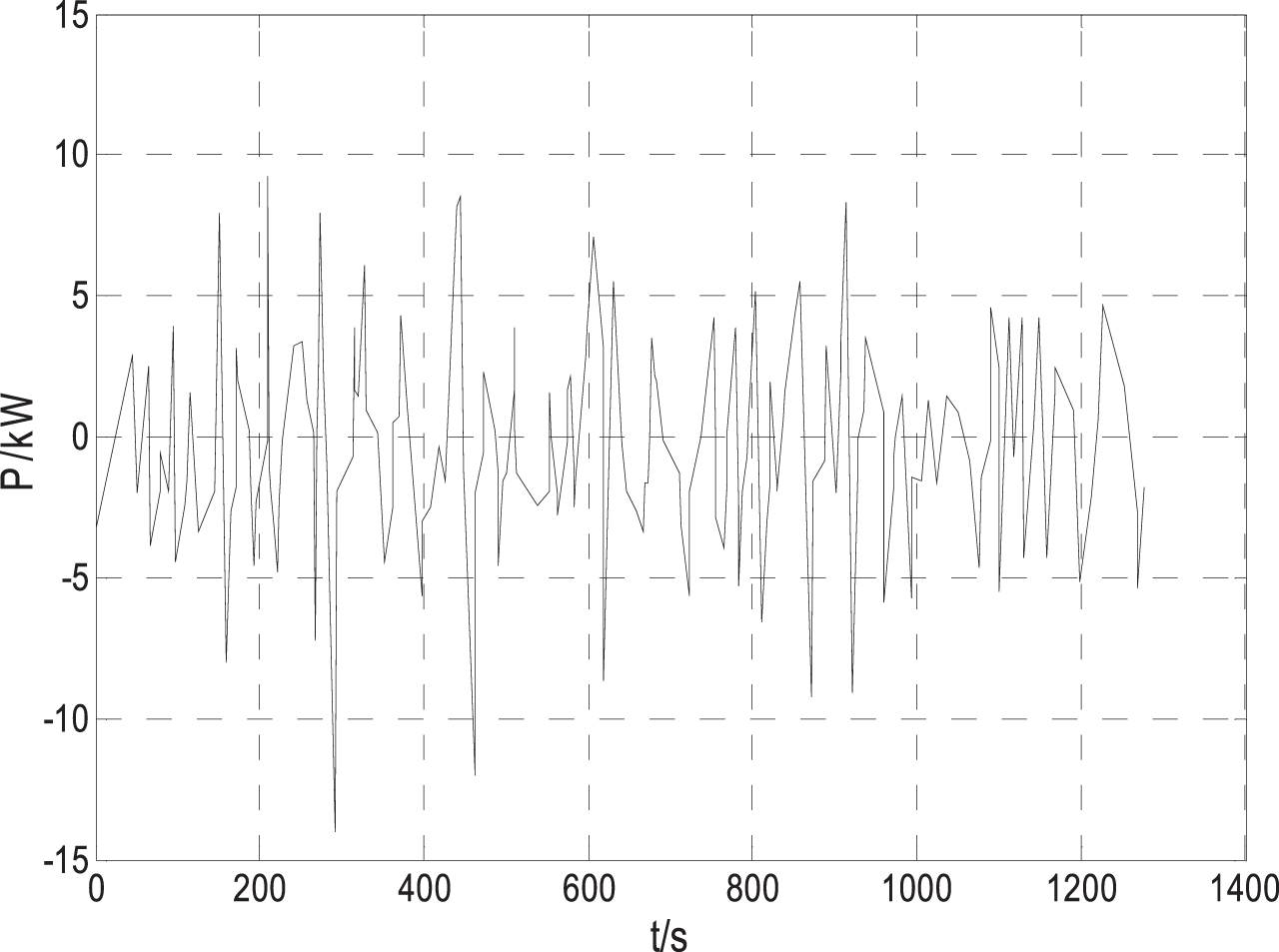
Battery output power.

Super capacitor output power.
The simulation results before and after the optimization in Table 7 show that the performance of the system has improved after optimization, and indicators such as hydrogen consumption and average battery current are all reduced compared to before optimization. This shows that the multi-objective optimization of the three-energy source system based on the above optimization idea is feasible.
Data comparison before and after optimization
This paper takes the three-energy system of hybrid fuel cell bus as the research object. On the basis of analyzing system working mode, parameter design and dynamic modeling, various energy management strategies were proposed and simulation modeling was completed. Finally, the vehicle design is realized. Multi-objective optimization of the membership function parameters of the fuzzy controller is carried out using the particle swarm algorithm. The fuzzy energy management strategy based on the particle swarm algorithm can not only meet the power demand of the working condition cycle, but also can adjust the fuel cell and power demand changes according to the power demand. By distributing energy to the capacitor and the battery, the change in the SOC of the battery pack and the energy distribution of each energy source can be well controlled, so that fuel consumption can be more effectively reduced and the impact on the fuel cell can be avoided. It achieves a good control of the changes in fuel cells, and more effectively reduces hydrogen consumption, thus verifying the feasibility and effectiveness of this improved strategy, providing a basis for the design of fuel cell vehicle controllers, and providing a basis for fuel cell vehicles.
Footnotes
Acknowledgments
This study was funded by Key R&D Projects in Hebei Province (Fund no.: 20312203D).