
Abstract
The electrochemical discharge machining process is affected by many factors, so the machining process is difficult to be qualitatively analyzed. In order to further understand the characteristics of the electrochemical discharge machining process and better master the machining skills, based on the image features, this article uses the SVM algorithm to build an electrochemical discharge machining system, and uses image feature recognition technology to effectively control the electrochemical discharge machining process. Moreover, this article analyzes the laser back-wet etching process mechanism and discusses the material removal mechanism of electrochemical discharge machining according to the three processes of bubble generation, gas layer formation, and spark discharge removal material. In addition, this article analyzes the system performance according to the actual situation and displays the results through statistical methods. The research results show that the electrochemical discharge machining system based on image features and SVM algorithm constructed in this paper has a good effect, and it can be applied to the management and control of the electrochemical discharge machining process.
Introduction
Electrochemical Discharge Machining (ECDM) is a new technology that has appeared in the field of special machining in recent years. It is commonly used in the machining of non-conductive materials such as heat-resistant glass, ceramics, industrial diamond, and quartz [1]. In the process of electrochemical discharge machining, when the voltage applied between the tool electrode (negative electrode) and the auxiliary electrode (positive electrode) is low (such as 12 V), only electrochemical reactions occur between the positive and negative electrodes, and hydrogen bubbles are generated on the surface of the tool electrode (negative electrode). The hydrogen gas film blocks the conduction between the electrode and the electrolyte after the hydrogen gas bubble generation rate reaches the mutual hydrogen gas film. When the voltage between the electrode and the electrolyte exceeds a certain critical value, it will break down the hydrogen gas film and produce a discharge phenomenon such as electrical discharge machining. At this time, the workpiece material close to the tool electrode is affected by the high temperature generated by the electrochemical discharge and the chemical etching at high temperature to remove the material to achieve the purpose of machining [2].
In recent years, microelectronic mechanical systems have developed rapidly and are playing an increasingly important role in industry. Therefore, the manufacture and application of MEMS have gradually attracted people’s attention. The microelectronic mechanical system is an advanced manufacturing technology platform. It is an integrated system based on semiconductor manufacturing technology to combine electronic functions with mechanical, optical or other functions, including automotive airbags, piezoelectric elements of inkjet printers, micro-optical reading heads, digital micro-mirror chips, pressure sensors, optical switching systems, etc. Moreover, it is widely used in automotive, electronic communications, biomedical, aerospace and other fields. MEMS belongs to a new field of multi-disciplinary intersect, the size is usually in the millimeter or micron level, and its focus is on ultra-precision machining [3].
Typical non-conductive brittle materials in micromachining are glass, quartz, silica, ceramics, etc. This type of material usually has excellent characteristics such as high hardness, high brittleness, high temperature resistance, wear resistance, corrosion resistance and organic compatibility, and glass also has good optical properties. Therefore, the micromachining technology of non-conductive brittle materials plays an important role in the manufacturing field of microelectronic mechanical systems.
Related work
In electrochemical discharge machining, the formation of the gas film depends on the full contact of the electrolyte and the tool electrode. However, as the machining depth increases, spark discharge becomes unpredictable, making it difficult to obtain good geometry and high machining speed. One of the main reasons is that the electrolyte is difficult to flow into the tiny gap between the electrode and the workpiece at this time. The literature [4] uses amagnetohydrodynamic (MHD) that can increase the electrolyte flow capacity to act on the ECDM process to improve the accuracy and efficiency of the process.
Theliterature [5] ensures sufficient flow of electrolyte by applying ultrasonic vibration to the electrolyte, which helps to achieve stable continuous discharge, thereby increasing the depth of ECDM drilling. In addition, with the help of side insulated electrodes and pulsed current, the stability of the gas film formation and the surface quality of the small hole entrance have been improved.
In view of the shortcomings of low efficiency, high energy consumption, and the inability to process deep holes and complex cavities in the electrochemical reaction film forming EDM method in the macro-scale electrochemical discharge machining, the literature [6] proposed a gas-filled electrochemical discharge machining method. This method replaces the electrochemical film formation process with a controllable physical aeration part, which shortens the discharge preparation time, strengthens the discharge effect, and significantly improves the machining efficiency. The literature [7] conducted machining experiments on polycrystalline diamond composite sheets and achieved good results. The method of physical inflation has a good machining effect on macro-sized workpieces. However, in microfabrication, it is difficult to realize the manufacture of microtubular electrodes and the air supply of small holes on the order of tens of microns, so the physical inflation method cannot be adopted in microelectrochemical machining. In electrochemical discharge machining, a reasonable gap servo feed between the tool electrode and the workpiece can obtain good machining quality [8]. The static pressure method is currently the most commonly used and simplest gap servo feed method. The tool electrode is completely in contact with the workpiece, and the machining process is easily monitored [9]. When using this method for servo feed, the static pressure needs to be controlled within a certain range. If the gap is too small, it may cause the fine electrode to break or bend. If the gap is too large, it can discharge but it cannot form an effective erosion of the workpiece material. In addition, the controllability and repeatability of the static pressure servo feed machining is poor, which is limited in actual machining [10].
Literature [11] studied the glass drilling usingstatic pressureservo-feed electrochemical discharge machining. Due to the systematic characteristics of this method, theliterature uses a special experimental method, using this method to study the influence of voltage, tool shape and force on machining. Through experiments, literature [12] found that in the process of electrochemical discharge machining, when using static pressure feed, two different physical characteristics appear at different drilling depths. When the drilling depth is within the initial 200∼300μm, the discharge characteristics are mainly controlled by the number of discharges in the gas film. At this time, the machining speed of the hole depth is very large (up to 100μm/s). For larger drilling depths, the drilling is mainly controlled by dynamic characteristics. At this time, the drilling speed is limited by the electrolyte flow in the tiny holes, so that the machining speed becomes slow (the typical speed is 10μm/s) [13]. The literature [14] adopted the gap equal speed servo feed method in the electrochemical discharge machining of micropores. To avoid damage to the electrode or the workpiece, the servo feed speed must be less than the machining speed of the microhole. However, the speed of electrochemical discharge machining of micropores is not a constant value, but it continues to decrease with the increase of the machining depth. When the feed speed is greater than the machining speed, damage to the electrode or the workpiece may also occur. The gap constant speed servo feed method still has the problem of poor controllability and repeatability of machining. The flexibility of electrochemical discharge machining is high, and it can realize a variety of geometric shapes [15]. By moving the tool electrode on the surface of the workpiece to do layer-by-layer removal similar to milling, some two-dimensional or even three-dimensional shapes can be processed. The literature [16] used different transmitters to process three-dimensional microstructures on glass. The literature [17] processed a linear structure with a width of 100μm and a length of several millimeters. The literature [18] realized the complex three-dimensional thread structure by electrochemical discharge machining. Applying a certain rotational speed to the tool electrode can improve the surface quality and geometry of the machined surface, and the faster the electrode moves on the workpiece surface, the better. The reason is that it can prevent thermal cracks on the workpiece surface. However, excessively high moving speed will reduce the material removal rate. The literature [19] used a method similar to “milling” to remove material layer by layer, and optimized parameters such as pulse voltage, electrode speed and feed speed. Moreover, the literature also showed some three-dimensional structures processed by this method, with a size of only a few millimeters. The literature [20] implemented the optimization of machining and strict control of the process to process slots with a width of 30μm and thin-walled structures with a width of 10μm on the glass, and the surface roughness reaches Ra0.1μm or less. This is probably the finest and most precise linear structure of electrochemical discharge machining so far. The article [23] dealt with IoT and human behaviour data with the collection and analysis of data from distinctive resources. The article [24] implements cooperative cognitive intelligence in the field of vehicular communication. The article [25] proposes the concept of SmartBuddy for implementing intelligent and smart city-based environments. The article [26] uses partitioning algorithm for speeding up the process of video processing. The article [27] does IoT and BigData Analytics in the real time environments using Hadoop ecosystem[28, 29].
Machining mechanism of laser backward wet etching
Focusing the laser on the liquid will produce various physical phenomena such as sound, light, and heat. This will cause the temperature of the focused area to rise sharply and induce a photochemical reaction. Photochemical reaction refers to the phenomenon that high-energy-density laser interacts with chemical substances, causing the internal ionic bonds or covalent bonds to break and recombine to form other substances.
During the laser back-wet etching process, the laser focuses on the solid-liquid interface of the workpiece material and the electrolyte. At this time, the metal cations in the electrolyte, such as Cu2+, will be reduced to produce nano-scale copper particles, and these particles will deposit on the lower surface of the workpiece and form a micro-textured deposit. Due to the existence of the deposited layer, the absorption rate of the bottom surface of the workpiece material to the laser is greatly increased, so that the local temperature rises and exceeds the melting point or even the vaporization point of the material to achieve material removal.
Laser irradiation not only increases the temperature in the electrolyte, but also changes the state of the liquid to produce cavitation. The incident laser energy density will determine the cavitation generation mechanism and cavitation type. In general, laser cavitation can be divided into plasma cavitation and vapor cavitation. Among them, when the laser energy density is low, that is, when the liquid vaporization conditions are met but the liquid cannot be broken down, the laser energy will cause the local liquid to rapidly heat up, expand in volume, vaporize, and exist in the form of bubbles. The bubbles at this time are vapor cavitation bubbles, and the positive pressure signal will be radiated outwards during the expansion of the bubbles. When the laser energy density is high enough to exceed the breakdown threshold of the electrolyte, the liquid absorbs the laser energy and undergoes strong resonance and ionization, forming a high-pressure, high-temperature plasma. The plasma expands rapidly and compresses the surrounding liquid, which generates plasma cavitation and emits shock waves to the outside [21].
After the cavitation occurs, the internal pressure will expand outward due to the huge internal pressure, and the internal pressure will gradually decrease. In this process, there will be a balance point where the internal pressure of the bubble is equal to the external pressure, but due to the inertial effect, the expansion will continue until the radius of the bubble reaches the maximum. At this time, the internal pressure of the bubble is already smaller than the external pressure, so the bubble will contract inward. During this process, a balance point where the internal pressure of the bubble and the external pressure are equal will appear, but due to the inertial effect, the contraction will continue until the radius of the bubble reaches the minimum. In this way, the cavitation has completed a cycle of expansion to contraction. Under the driving of internal and external pressure, the cavitation will repeat the important process many times. This process is the cavitation pulsation. Figure 1 shows the cavitation pulsation process captured by the high-speed camera.
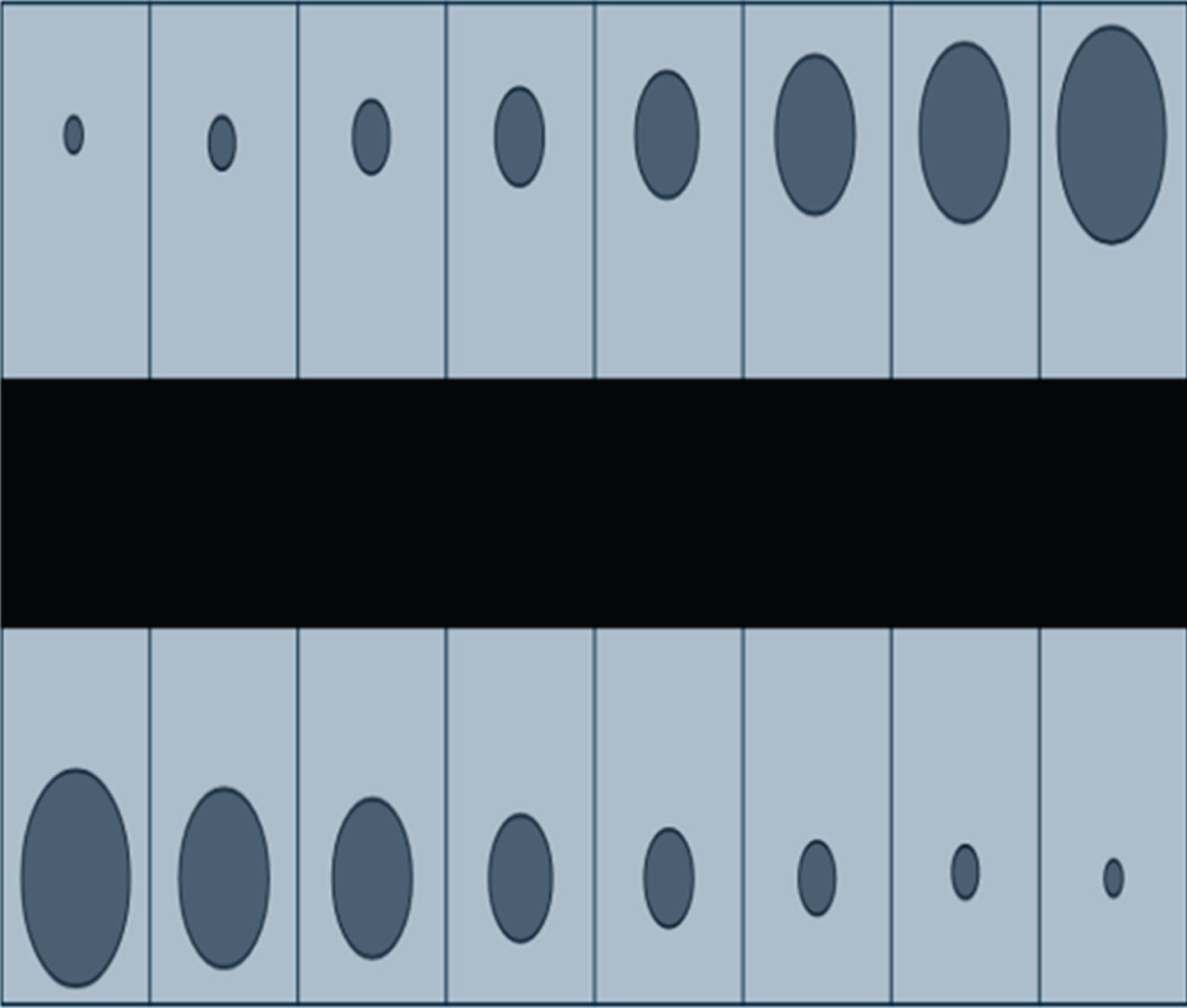
Laser cavitation pulsation process.
By using the Rayleigh formula, the maximum radius of the bubble can be solved after derivation:
Among them, Rmax is the maximum radius of cavitation expansion, ρ l is the density of the liquid, and T c is the cavitation pulsation period. Meanwhile, P o is the cavitation external pressure, which is approximately equal to the atmospheric pressure, P i is the cavitation internal pressure, and E b is the cavitation energy. According to these two formulas, the maximum radius of vacuole expansion can be calculated by substituting the value of the pulsation period to further calculate the energy of the vacuole.
During the pulsation process, the cavitation bubble will send out shock waves, and the collapse of the cavitation bubble will also produce a jet impact. Most of the two will exert a force effect on the workpiece material to promote the removal of the material. Especially when the cavitation collapses, the impact of the high-energy jet generated has a very important role in the process of material failure and destruction, and separation from the matrix. By using the water hammer impact force formula, the impact pressure of the jet generated by the collapse of the cavitation bubble can be calculated [22]:
Among them, P2 is the impact pressure of the jet, ρ1 is the density of the liquid, and c1 is the propagation speed of the sound in the liquid. At the same time, ρ2 is the density of the workpiece material, c2 is the propagation speed of the sound in the workpiece material, and v is the velocity of the jet impacting the surroundings.
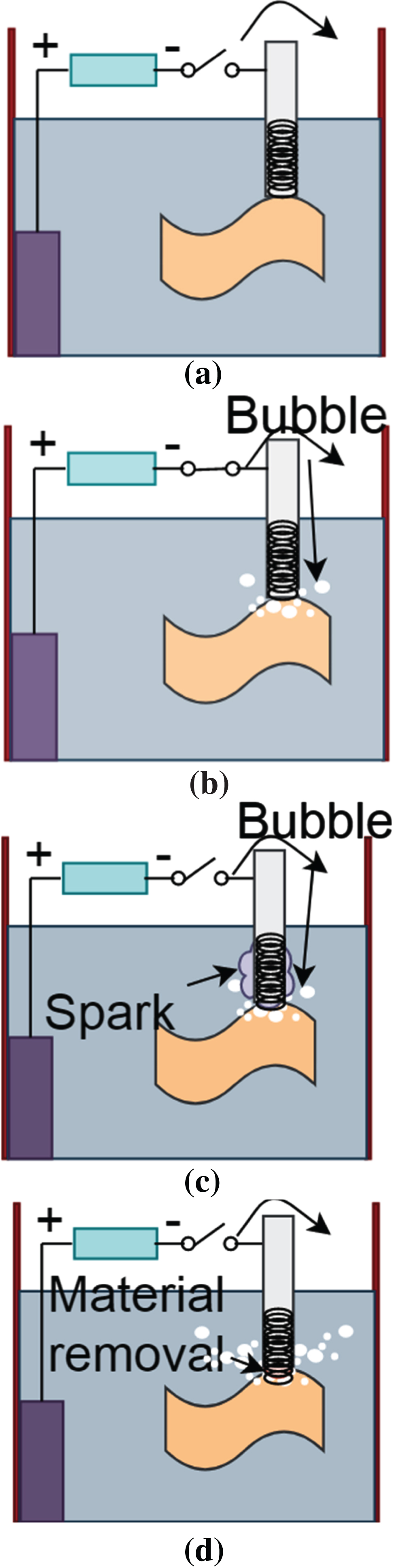
Combined with the above analysis, the mechanism of laser back-wet etching can be summarized as follows: the laser focuses on the solid-liquid interface, causing the local temperature to rise, reducing and depositing the metal cations in the electrolyte on the bottom surface of the workpiece material (as shown in Fig. 2(a)). The deposited layer greatly improves the absorption rate of the material to the laser, and the material is removed in the form of melting or vaporization, accompanied by cavitation. When the bubble collapses, the jet impact acts on the workpiece material, destroys the deposited layer and discharges the material debris together (as shown in Fig. 2(b)), and then repeats the process of depositing to the chip removal, thereby achieving the material etching process.

Schematic diagram of the principle of laser back wet etching.
The auxiliary electrode made of graphite is connected to the positive pole of the DC pulse power supply and serves as the anode of the electrolysis reaction. The tool electrode is connected to the negative electrode of the power supply as a cathode, and the auxiliary electrode is immersed in the alkaline electrolyte. The tool electrode penetrates into the electrolyte at a certain distance and is closely attached to the upper surface of the workpiece material (as shown in Fig. 3(a)). After the circuit is connected, the electrolytic reduction reaction will occur around the tool electrode. H+ is reduced to generate hydrogen and precipitate out. These hydrogen floats, bursts or condenses into large bubbles in the form of bubbles (as shown in Fig. 3(b)). When there are enough bubbles, these bubbles will fuse with each other to form a gas layer, and the tool electrode and the electrolyte will be separated. At this time, a large electric field strength will appear between the electrolyte and the tool electrode. When the voltage continues to rise and reaches the critical voltage of spark discharge, spark discharge will occur on the surface of the tool electrode (as shown in Fig. 3(c)), which will break through the gas layer and impact the workpiece material, eroding the material at high temperature (as shown in Fig. 3(d)).

Schematic diagram of the principle of electrochemical discharge machining.
Electrochemical discharge machining is roughly divided into three stages of bubble generation, gas layer formation, and spark discharge material removal in chronological order. The machining mechanism will be analyzed based on a series of physical and chemical changes and motion states that occur in the three stages.
As mentioned above, after the machining system circuit is connected, a reduction reaction occurs around the tool electrode as the cathode to generate hydrogen. The chemical equation is:
Cathode:
Correspondingly, an oxidation reaction will occur around the auxiliary electrode as the anode to produce oxygen, and the chemical equation is:
Anode:
It can be seen that there will be gas precipitation on the surface of the auxiliary electrode and the tool electrode, but because the surface area of the auxiliary electrode is much larger than the surface area of the tool electrode (geometric difference), and the volume of gas deposited at the tool electrode is twice that of the auxiliary electrode. Therefore, a large number of bubbles fusing to form a gas layer can only appear on the surface of the tool electrode.
It is possible to define a function that changes the bubble radius with time, and assume that the bubble is spherically symmetric in spherical coordinates, according to the Navier-Stokes equation:
In the formula, u
r
(t, r) represents the expansion rate of bubbles at any position in the electrolyte, ρ
r
represents the density of the electrolyte and is a constant, and p is a function that characterizes the pressure change of bubbles with distance and time. The following equation for the expansion rate of bubble expansion can be obtained:
It may be assumed that the radius of the hydrogen bubble at the junction with the electrolyte is R, and the above equation is integrated from R to infinity. The relationship between the bubble expansion rate
Therefore, it can be obtained:
From R to infinity, Equation (9) is integrated to obtain the following differential equation:
The situation that the pressure on the bubble is affected by the internal pressure p
i
and the surface tension σ of the bubble is considered, so the above formula is transformed into:
From this formula, we can know the change of the radius of a single hydrogen bubble. The electrolyte density, surface tension coefficient and boundary pressure involved in R (t) are constants.
The gas layer is composed of a large number of individual bubbles undergoing complex changes, such as expansion, contraction, breakage, etc., and finally merged to form. The principle and method of gas test.
As shown in Fig. 5, during machining, the tool electrode is immersed 2 mm below the liquid surface and connected to the negative pole of the pulse power supply, and the auxiliary electrode is connected to the positive pole of the pulse power supply. After the circuit is connected, an electrolytic reaction occurs around the electrode of the tool to generate hydrogen gas. These hydrogen gas floats, bursts, or converges into large bubbles in the form of bubbles (as shown in Fig. 5(b)). When there are enough hydrogen bubbles, these bubbles will fuse with each other to form a gas layer. The tool electrode and the surrounding electrolyte are separated. A strong electric field strength appears between the electrolyte and the tool electrode. When the voltage continues to rise and reaches the critical voltage of the spark discharge, a spark discharge will occur on the surface of the tool electrode (as shown in Fig. 5(c). Spark discharge breaks down the gas layer, accompanied by high-temperature and high-pressure plasma bombarding the workpiece, melting and removing the material and softening part of the material. At the same time, due to the mechanical grinding effect caused by the rotation of the tool electrode, this part of the material is removed by cutting (as shown in Fig. 5(d)).

Schematic diagram of gas layer formation process.
Schematic diagram of the electrochemical discharge composite mechanical grinding process.
The process of grinding needle electrode using mechanical grinding to assist spark discharge to remove ceramic material belongs to the category of indentation fracture mechanics, from which a mathematical model of indentation fracture mechanics can be established for research. During the machining process, the high-speed rotating grinding pin electrode can be equivalent to the cylindrical grinding wheel to grind the ceramic material. When the diamond abrasive particles bonded on the surface of the grinding pin contact the ceramic material, a certain load pressure will be generated. When this pressure is less than the critical threshold, there will be no transverse cracks in the ceramic material, which is mainly removed in the form of plastic deformation. Meanwhile, when this pressure is greater than the critical threshold, the ceramic material will be removed in the form of brittle fracture, and the material has no obvious deformation. However, invisible lateral cracks may appear on the processed surface. The following cut-thickness equation for the critical condition of brittle ductility transition can be used for grinding of ceramic materials.
In the above formula, alim is the critical depth of indentation, H is the hardness of the workpiece material, and K
IC
is the fracture toughness of the workpiece material. At the same time, E is the elastic modulus of the workpiece material. During the grinding process, the diamond abrasive particles will also be subjected to reverse load pressure, and this load pressure is dynamically changing. According to the test results of Shi Xingkuan and others, the fracture toughness of the workpiece material should be 0.3K
IC
. Formula (12) is transformed into:
After the diamond abrasive particles are cut through the ceramic material, a large number of fine grinding marks will be left on the processed surface. Their shape and size are irregular, and the grinding marks overlap or stagger each other. Due to the different depth of the wear scar left by the abrasive grains, the undeformed cut thickness produced by each abrasive grain is also different. The maximum undeformed cutting thickness produced by the abrasive particles will ultimately affect the machining process by affecting the grinding force, the temperature of the machining area and the specific grinding energy. The relationship between the machining parameters, the distance between the grinding edges during continuous grinding and the maximum undeformed grinding thickness produced by the abrasive grains satisfies the following equation:
In the above equation, hmax is the maximum undeformed grinding thickness, λ sd is the grinding edge spacing during continuous grinding, and v t is the linear velocity of the workpiece material. Meanwhile, v g is the linear velocity of the abrasive grains, a h represents the depth of the wear scar, and d g represents the diameter of the equivalent grinding wheel. It can be seen that when the maximum undeformed grinding thickness hmax produced by abrasive particles is less than alim, the workpiece material is mainly removed in the form of plastic deformation; when the maximum undeformed grinding thickness hmax produced by abrasive particles is greater than alim, the workpiece material is mainly removed in the form of brittle fracture.
In the experiment, the three-coordinate motion platform was used to control the tool electrode to contact the upper surface of the workpiece, and then raise 5μm upward to complete the tool setting. The tool electrode reciprocates in the horizontal direction, and feeds 50μm downwards every time it reciprocates, thereby machiningmicroslots. At the same time, the tool electrode rotates along the vertical central axis, playing the cutting role of diamond abrasive particles to remove the parts that are difficult to process by spark discharge, and improve the machining quality. The frequency of the power supply has a great influence on the formation of the gas layer. The voltage of the power supply is closely related to the strength of the spark discharge. The speed of the tool electrode characterizes the strength of the mechanical grinding. The following will carry out the micro-slot machining test around the above three parameters. The test results are detected by scanning electron microscope and confocal material microscope to study the effects of electrochemical action, spark discharge action and mechanical grinding action on machining.
In the copper sulfate solution, the picosecond laser is used to etch the glass back. The machining mechanism is much more complicated than the laser directly machining the glass. Laser direct machining of glass materials mainly relies on thermal effects to remove the glass materials. However, laser irradiation in the liquid environment will cause photochemical reactions, photothermal phenomena, cavitation, jet impact and other phenomena. It will also induce the reduction of copper ions and form a deposit on the glass surface. The deposited layer will greatly increase the laser absorption rate of the material, thereby accelerating the etching process rate.
The temperature change of the copper sulfate solution and the glass material caused by laser irradiation is a prerequisite for the etching process, so it is necessary to analyze the temperature field. The pulse width of the picosecond laser is very short, between 10-9s and 10-15s. There may be two types of removal of the back etching of the glass: one is that the temperature of the liquid rises instantaneously under the action of laser irradiation and exceeds the melting point of the workpiece material, and the material is melted and removedTaking the laser beam with a wavelength of 1064 nm as an example, the energy of a single photon is about 1.17 eV, which will make the laser beam with a wavelength of 1064 nm in the liquid as an example, the energy of a single photon is about 1.17 eV. The other is the laser-induced photochemical reaction in the solution, which produces a deposited layer and attaches it to the surface of the workpiece material. This improves the material’s absorption rate of the laser and melts and removes the material. However, the transient temperature of the liquid is difficult to measure, so the method of numerical simulation is often used to study.
Because the diameter of the laser spot is much larger than the characteristic size of heat conduction, the one-dimensional heat conduction model can meet the requirements. Therefore, the heat conduction is shown as follows:
In the above formula, the initial value of the temperature is the ambient temperature T o , D represents the thermal diffusion distance, and S represents the equivalent heat source formed by the laser irradiation of the copper sulfate solution. The heat conduction in a multi-media environment changes with the material of the contact surface. Figure 6 shows a schematic diagram of heat transfer in the laser irradiation area. Both the copper sulfate solution and the glass workpiece use semi-infinite bodies, area R1 represents the copper sulfate solution, and area R2 represents the transparent glass material.
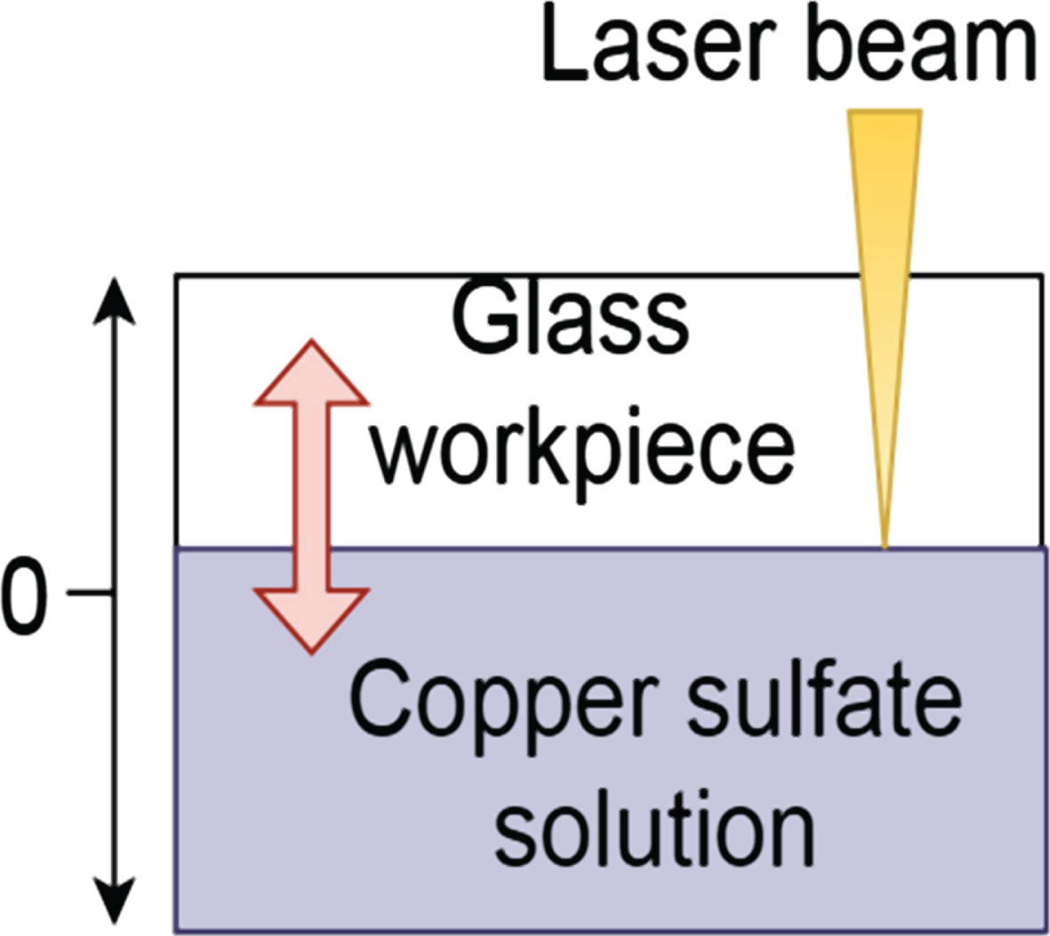
Schematic diagram of heat transfer in the area irradiated by laser.
It is assumed that the glass is completely transparent, the energy of the laser beam is completely absorbed at the solid-liquid interface, and the impact of jet impact and plasma on heat conduction is ignored. Therefore, the heat conduction equation of the workpiece and the solution area can be obtained:
For area R1, there are:
The thermal conduction boundary conditions in the two regions can be expressed as:
The thermal conduction boundary conditions at the solid-liquid interface can be expressed as:
It is assumed that the absorption of laser energy in region R1 is linear, we obtain:
In the above formula, T p represents the laser pulse width. The above formula only considers the liquid temperature field distribution under the action of a single pulse. The partial differential equation of the heat conduction process can also be obtained through Laplace and Fourier transform.
This article mainly studies the different stages of electrochemical discharge machining based on image recognition algorithms. From the actual situation, different image features will appear in different stages of electrochemistry. Therefore, this paper combines the SVM algorithm to build an image recognition system. The system constructed in this paper is shown in Fig. 7.
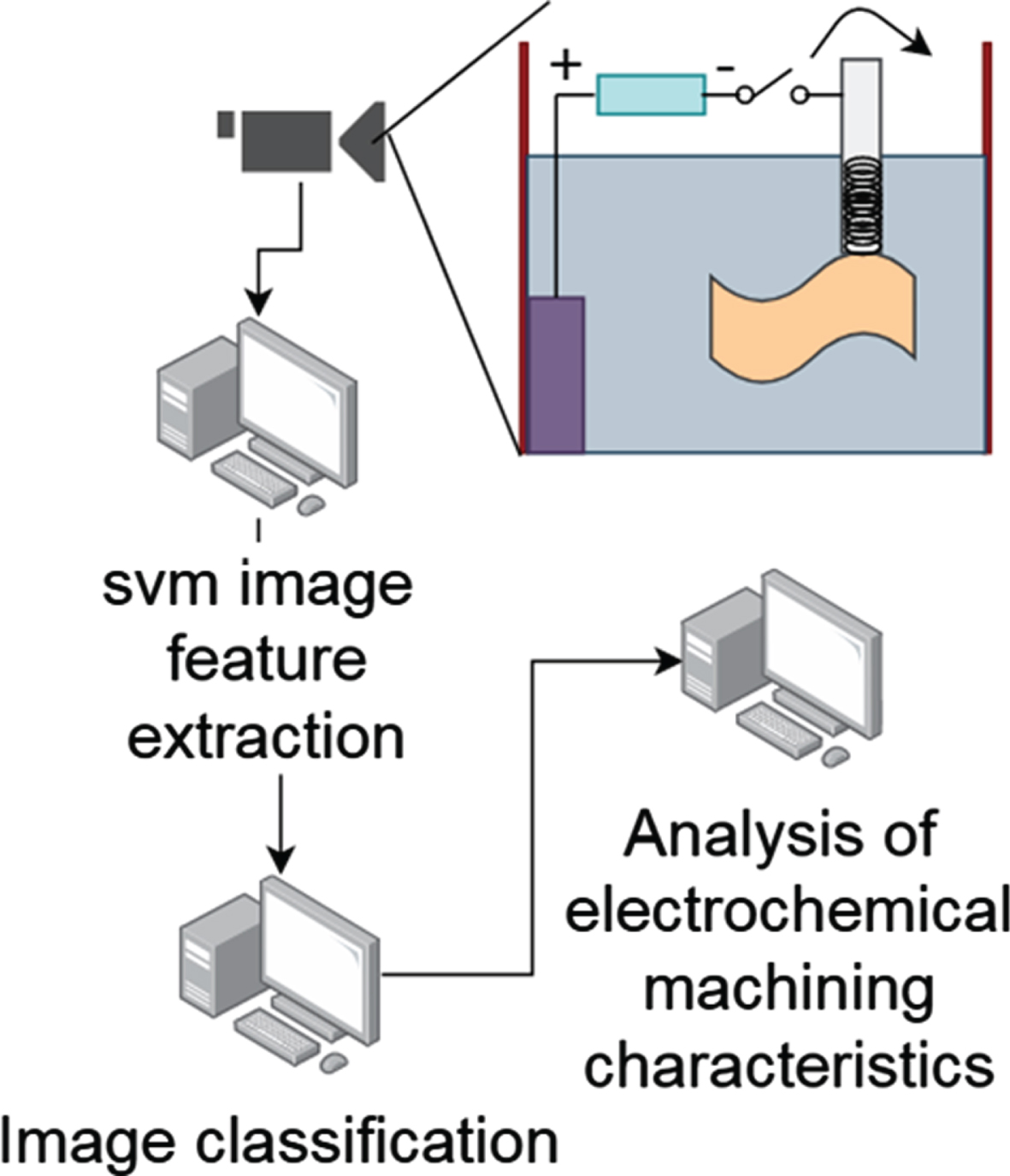
Electrochemical discharge machining recognition system based on image features and SVM algorithm.
On the basis of constructing the above model, this research studies the system performance. The parameters selected in the test are as follows: the machining object is lmm 304 stainless steel sheet, the working fluid is tap water, the tool electrode speed is 12000 rpm, and the tool electrode feed speed is 20 um/s. Moreover, the feed distance of the two-dimensional plane is 10 mm, the machining voltage is 30 V, the pulse frequency of the power supply voltage is 25 kHz, and the tool electrodes of different diameters are 0.5 mm, 0.55 mm, 0.6 mm, 0.65 mm. The electrochemical discharge milling test was carried out using the above-mentioned predetermined machining parameters to obtain the unilateral side clearance and slot width of the slots processed by tool electrodes of different diameters.
It can be seen from Table 1 and Fig. 8 that when the diameter of the tool electrode is small, the electrode end jumps with a certain amplitude under the condition of high-speed rotation, the surface bubbles are not easy to collide and merge into a dense gas film layer, the discharge frequency is reduced, the slot width is small, and the unilateral side gap value is large. As the diameter of the tool electrode continues to increase, the slot width of the machiningslot gradually increases, and the single-sided side gap value gradually decreases. At this time, the centrifugal force generated by the tool electrode in the machining gap is large, it is easy to form a dense gas film layer, which is conducive to reaching the discharge condition, and the material removed by the electric spark becomes more. However, when the tool electrode is increased to 0.65 mm, the electrochemical reaction is enhanced, and the more bubbles generated by the electrolyzed water on the surface of the electrode. When EDM does not break through the gas film to remove the material, the machining gap will be filled with continuous bubbles, which is not conducive to reaching the discharge condition, so the slot width will be reduced.
Test data under different electrode diameters

The effect of different tool electrode diameters on the results.
The electrochemical discharge milling machining test is performed using the above-defined machining parameters to obtain the unilateral side clearance and slot width at different rotation speeds of the tool electrode, as shown in Table 2.
Test data at different rotation speeds
It can be seen from Table 2 and Fig. 9 that when the rotation speed of the tool electrode is small, the electrochemical reaction is more obvious at this time, and the electrolyzed water at the end of the electrode generates a mess of large-scale bubbles, which is not conducive to the formation of a dense gas film layer, and the discharge phenomenon is not obvious, and the gap and width of the unilateral side of the machiningslot are small. When the speed increases to 12000 rpm, the unilateral side clearance value and slot width increase obviously. This is because the centrifugal force generated by the increase in the rotation speed becomes larger, the messy bubbles in the machining gap gradually decrease, the discharge range is expanded, and the number of discharges is increased.
The effect of different tool electrode rotationspeeds on the results.
This paper mainly analyzes the mechanism of laser back-wet etching based on photochemical reaction and cavitation effect and discusses the material removal mechanism of electrochemical discharge machining by combining three processes: bubble generation, gas layer formation, and spark discharge removal. Then, this paper analyzes the machining mechanism after the combination of laser and electrochemical discharge. Moreover, this paper builds a stainless steel micro-slot electrochemical discharge milling machining test device platform, and selects pulse power supply, tap water as the machining power and working fluid to carry out the stainless steel micro-slot electrochemical discharge milling machining test. In addition, this paper studies the influence of two machining parameters of tool electrode rotation speed and diameter on the machining results. Through theoretical analysis and experimental machining results research, it was found that as the tool electrode speed increased, the denser the gas film formed, the discharge phenomenon became obvious, and the material removal rate increased accordingly, so as to achieve the purpose of stable machining. From the research results, it can be seen that the electrochemical discharge machining system constructed in this paper based on image features and SVM algorithm has a good effect, and it can be applied to the management and control of the electrochemical discharge machining process.
Footnotes
Acknowledgments
This study was supported by Open Research Fund Program of Shaanxi Key Laboratory of Non-Traditional Machining (Grant No. SXTZKFJJ201904); Doctoral Foundation Project of Longdong University (Grant No. XYBY1905).