
Abstract
In order to effectively control the vibration transmitted from the ground to the precision equipment, permanent magnet linear synchronous motor (PMLSM) can be effectively applied in the active vibration absorber systems due to its good characteristics. The design of a PMLSM is very important because of the special requirements of the damping system on the response speed, working temperature, working bandwidth and installation size of the PMLSM. In this paper, the multi-objective design problem of the PMLSM in vibration damping system is proposed. Based on the equivalent magnetic circuit analysis of the PML SM’s air gap magnetic field, the performance and design of the PMLSM are effectively analyzed in combination with the design objectives. The design and performance of the prototype meet the design requirements.
Introduction
In precision, especially ultra-precision manufacturing, such as microelectronic processing and microelectromechanical systems (MEMS). With the development of micro-processing technology and biotechnology, ultra-precision positioning platform is needed in more and more occasions to provide a carrier platform that can realize ultra-precision positioning and precise movement in such fields as lithography technology, numerical control processing, biotechnology and nano-surface topography measurement [1–3]. However, in order to ensure the stability of the ultra-precision positioning platform, the importance of the precision vibration reduction platform is increasingly prominent. It isolates the disturbance vibration from the outside world (such as the earth) from the ultra-precision positioning platform and provides a quiet external environment for the ultra-precision positioning platform [4, 5].
The PMLSMs are similar to their rotary counterparts [6, 7]. They have high thrust density, robust design, good overload capacity, and sinusoidal flux linkages. Also, there is scope to modify the linear motor designs to operate as a linear generator [8–10]. The PMSLMs offer high precision, low maintenance and excellent dynamic characteristics. Due to these outstanding advantages, they are very suitable to be used as actuators in the vibration absorber systems, so it is of great significance to carry out relevant research for further understanding of the vibration absorber systems.
Design of active vibration damping
Simplified model of vibration absorber systems
For the general (passive) damping system, the force model can be simplified to the lower left diagram (as shown in Fig. 1), where k and c1 are springs and damps.

Schematic diagram of passive vibration absorber systems.
Through force analysis of M, it can be concluded that
It can be seen from the stress analysis in the above right Fig. (as shown in Fig. 1) that when there is a local vibration, object M2 (the vibration isolation object) must be affected by the ground vibration, because M2 is affected by the unbalanced force, i.e., the force alone, F. If you want M2 to remain stationary, the simplest and most direct way is to apply an opposite force on M1, F2, when F1 is applied to M2. As shown in Fig. 2:

Force analysis of the loaded.
When F1 and F2 are produced at the same time, and F1=F2 is produced, M2 will remain in the original static state. This serves the purpose of vibration isolation. But there is a prerequisite: F1 and F2 are produced together, and F1=F2. In order to achieve the “simultaneous” effect, the PMLSM is applied to the vibration damping system as a force F2 generator because of its fast response and direct application of force (eliminating the intermediate transmission link). Because ideally F2 and F1 are produced at the same time, so F2 is just a damped force. This simplifies F2 to the force generated by damper c2.

Schematic diagram of active vibration absorber systems.
At this moment
Substitute in the expression analyzed
For a first-order damping system, its damping can be ignored according to the design (only the second-order part is discussed here), that is c1= 0, so the above equation can be simplified as
1) solve the characteristic equation
2) no motor action
If the motor does not act on the damping system, that c2= 0
Although the amplitude-frequency characteristic curve in the Byrd diagram of the damping system decreases rapidly at the cut-off frequency (–401b/dec), the step response of the damping system will be equal amplitude oscillation. But it is possible to make M2, by changing the k1 magnitude, gradually decrease the amplitude of the oscillation, so as to achieve “stability”.
In the topology of the PMLSM, all magnets are magnetized in the same direction, meanwhile, the magnets in adjacent teeth are oppositely magnetized. In the mover, the coil is supported and fix on the frame by corns, as shown in Fig. 4. The working conditions of the PMLSM are shown in Table 1.

Structure diagram of permanent magnet linear synchronous motor.
Motor operating conditions
The heat dissipation performance of the actuator reflects the thermal design level of the motor and also limits the maximum heating power of the coil. Since the design of the rotor cooling system has not been completed, the maximum allowable heating power of the rotor can only be estimated from the given water cooling technical parameters. According to the dynamics, there are:
P –density of cooling water, 103 kg/m3 C –specific heat capacity of water, 4.187KJ/ (Kg*°C) Q –water flow, according to the actual design level of the Δ –Temperature rise of cooling water, the normal working temperature of the coil is 25°C and the in flow temperature of cooling water is 22 °C then
According to the target force constant of the motor
Into (1)
n —the number of turns of B
g
—magnetic induction intensity of I —conductor l0 —Effective length of on
It can be seen from Ansoft simulation diagram (as shown in Fig. 5 that the magnetic induction intensity in the working area of the coil is approximately equal. Then, the turns of the coil are optimized according to the limitation of installation size and technological requirements.

Thermal analysis of motor. (a) Front view. (b) Top view. (c) Side view.
Winding coil can be wound with adhesive polyester enamelled wire, the percentage of copper sectional area in the conductor’s sectional area is about 65–75%, plus the gap caused by manual winding, etc. take the window ratio of the wire of the coil cross section (i.e., the ratio of copper effective area to window area) C = 0.6, then the copper sectional area of the enamelled wire of single turn can be calculated
S —cross-sectional area of the coil
Then enameled wire:
After careful design, the thrust coefficient of LM fulfills the goat and the heat dissipation becomes the hot point. The effect is verified by ANSYS and the results are shown in Fig. 5. The design of heat dissipation can satisfy the constrains except several points.
The voltage equation of the coil winding of permanent magnet linear synchronous motor is
Among
ψ
f
—the magnetic field chain of a permanent magnet: L
sσ
, L
ml
—winding leakage inductance and excitation inductance; R —motor coil resistance
Available
Through the magnetic field Ansoft simulation of Lorentz motor as shown in Figs. 6 and 7, it can be

2D FEM results. (a) Cloud chart. (b) Permanent magnet linear.
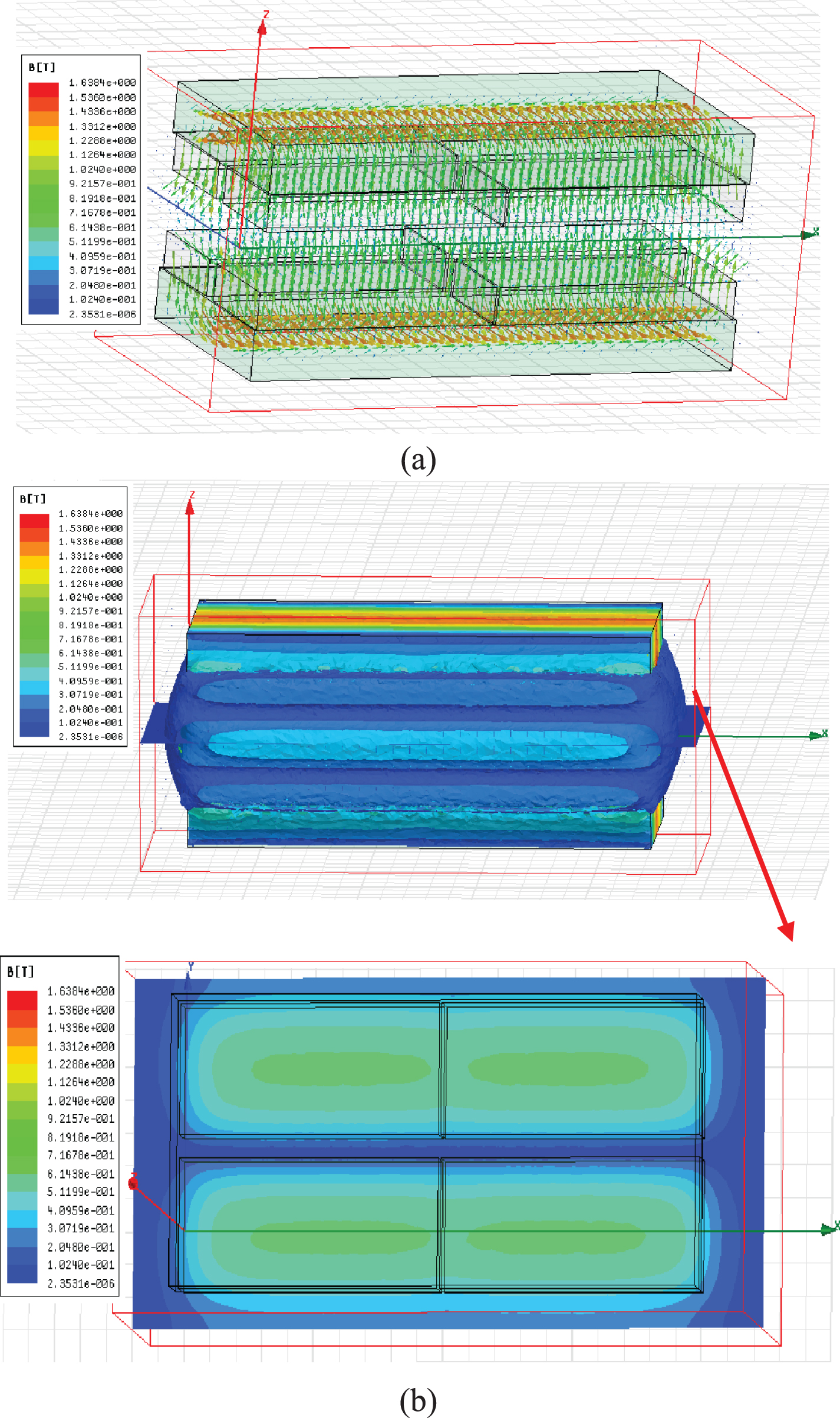
3D FEM results. (a) Permanent magnet linear. (b) Cloud chart.

Magnetic equivalent circuit diagram of permanent magnet linear synchronous motor. (a) Structure of the stator. (b) The magnetic equivalent circuit of stator. (c) Simplified magnetic equivalent circuit of stator.
The basic idea of equivalent magnetic circuit is to analyze the magnetic field in a circuit like way. Similar to the circuit analysis method, it is based on Kirchhoff voltage law and Kirchhoff current law to build the magnetic circuit model of the magnetic field [11–13]. Compared with the methods of mathematical analysis and numerical analysis, the equivalent magnetic circuit method has the advantages of relatively simple model, easy parameterization and less calculation time.
Structure of the stator is shown in Fig. 8. To avoid magnetic saturation, the geometric size and material properties of the steel-yoke have been chosen elaborately. The air gap between the two magnet poles has width g; t is the gap distance between adjacent poles; l m and l s represent the thickness of the PM and steel-yoke, respectively. w and w m denote the weight of the steel-yoke and PM, respectively.
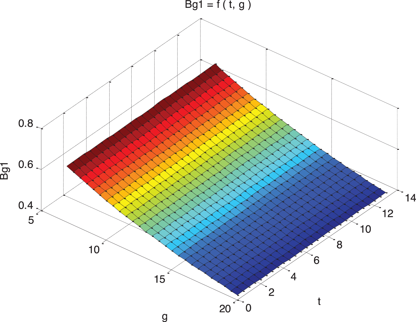
Relationship between the magnetic induction intensity of intermediate air gap and g and t.
Air gap magnetic field analysis
Where ϕ s is the flux source of the magnet pole; R m is the reluctance corresponding to flux ϕ s . Rg denotes the reluctance of the air-gap between two magnet poles. R t is the reluctance of the gap distance between adjacent poles. μ0 represents air permeability. μ R and μs represent the relative permeability of the PM and steel-yoke, respectively. A g is the flux surface area of air gap. A m and A t are the flux surface area of the magnet pole and the gap distance, respectively.
The effect of g and t on B g is plotted in Fig. 9, This Fig. explains that g plays a prominent role and the relationship is magnetic density on air gap increases as reducing g. Although t has similar effect to MFD on air gap, by contrast, it is too slight to sense the change.
It is known that the magnetic induction intensity of Lorentz motor magnetic field is distributed symmetrically as shown in Fig. 10.

Diagram of air gap magnetic induction intensity.
When the motor coil moves, the maximum displacement is 1 mm, as shown in Fig. 11. The dotted line is the B value curve of the middle line of the upper and lower permanent magnets. The solid wire frame is the line group of the moving coil, the black wire is the initial position of the winding of the moving coil, and the blue wire frame is the position of the winding after electrification. a is distance traveled (within the time interval).

Schematic diagram of electric motor and stator mutual micromotion.
Because the air gap magnetic field between the upper and lower permanent magnets is symmetrical. Thus, when the moving coil is electrified, the flux of the chain through the coil remains unchanged.
It can be obtained:
And ignore the external characteristics of the back electromotive force due to the change in the current
So
By carrying out Laplace transform, we can obtain:
The equivalent circuit diagram of PMLSM sub-coil is shown in Fig. 12, and it can get

PMLSM sub-coil model.
According to the circuit equation of the coil:
From the above equation, it can be seen that the response of the coil output to the voltage or current signal is a short time delay (about 41 ms), the stable value of
The control block of LM in vibration absorber can be observed in Fig. 13.

PML SM sub-coil model.
As shown in Figs. 13 and 14, there is a delay effect in the execution of the motor as an actuator (especially in the high frequency range), in order to provide the effect of damping (acting force), the corresponding control algorithm and strategy can be introduced in the control to improve the damping control.

The control block diagram of LM in vibration absorber system.
Static test
As shown in Fig. 15, the blue line in the Fig. is the motor output –current relationship line tested, and the red line is y = 32x - 1.3.

Motor force-current relationship.
According to the frequency-domain characteristic curve of the actuator, as shown in Fig. 16, the working frequency band of the motor as the actuator is about 0–260 Hz. With the increase of the working frequency of the motor, its delay effect will increase continuously. In the range of 100–260 Hz, the time delay changes significantly with the working frequency of the motor. It also shows the necessity and importance of introducing the control algorithm to improve the actuator delay.

Working bandwidth diagram of permanent magnet linear synchronous motor (actuator).
In this paper, the research on the PMLSM is limited to the actuator of the precise active damping system. It can be used as a reference for other application scenarios.
According to the actual requirements, the dynamics, magnetic field, temperature and control of permanent magnet linear synchronous motor in the precision active vibration damping system are analyzed and optimized. Its performance is studied, and the improvement suggestions of its delay effect are put forward. Simulation and experimental verification and testing were carried out. The validity of the analysis and design of permanent magnet linear synchronous motor is proved.
Footnotes
Acknowledgments
This article was supported by the National Natural Science Foundation of China under Grant 51965030, the Yunnan Applied Basic Research Project under Grant Number 2017FB091, the informatization construction project of Ministry of Public Security Material Certification Center under Grant SGS2019102901, the key project of technology research program funded by Yunnan Province under Grant 2016RA042, the Innovation Fund for Technology based firms in Yunnan Province under Grant 2017EH028, and the Ministry of public security technology research program under Grant 2016JSYJA03.