
Abstract
An electronic glove is a sensor-equipped glove for detecting changes in the motion or the bending of a finger. The function of an electronic glove can replace the function of a remote control, especially for people with disabilities. In this study, we designed and realized a glove equipped with a flex sensor on each finger to detect the bending of the finger and used a mobile robot as the plant of the electronic glove. The system works by detecting finger-bending in the right hand and processing it into the commands stop, forward, backward, forward left and forward right. The flex sensor resistance value caused by the finger-bending is used as an input for fuzzy logic control and produces the output to control the mobile robot. The flex sensor is capable of varying values between normal conditions of 27.2 kΩ up to a maximum of 46 kΩ. The lowest speed of the mobile robot is 0.75 m/s, with a maximum speed of 2.17 m/s. The commands from the electronic glove are sent to the mobile robot wirelessly with a maximum distance between electronic glove and the mobile robot of 200 m in an obstacle-free situation. Based on the experimental results, 100% of the orders were executed according to the design. The use of fuzzy logic ensures that every bending change is accompanied by a change in speed, so that mobile robot movements become smoother.
Introduction
An electronic glove is a glove equipped with a sensor to detect finger motion or hand position. Sensors that can be used to detect such movements include flex sensors, accelerometers or cameras. This electronic glove technology can be utilized for persons with disabilities to control an electronic device [1–3]. In addition, electronic gloves can be used in the healing process of diseases as discussed in [4–6].
Research into the development of electronic gloves using flex sensors has been performed by [7–9], among others. In [7] electronic gloves with flex sensors were developed to control a robot arm. The flex sensor used in the study only detects one finger change and therefore cannot be used with a combination of fingers. In [8] electronic gloves were developed which used combinations of three fingers to control the robot. The development of soft flex sensors from the point of view of design and materials, is described in [9].
Other research in the development of flex sensors concerns hand motion control. Hand motion control is the result of innovation in the implementation of flex sensors placed on the fingers to control a tool or operate a controller [5]. Plants that can be controlled through hand motion control include bionic hands, quadcopters, cranes [10] and mobile robots.
In this study, we designed and realized an electronic glove equipped with flex sensors in each finger to detect the bending of a finger. Combinations of finger-bending movements were used to move a mobile robot plant, with movements defined using the fuzzy logic method. Utilization of the fuzzy logic method for mobile robot control has been investigated in [11–15], among other studies.
Research method
Block diagram
Figure 1 shows the overall system block diagram. First, the flex sensor detects a change in the bending of fingers, producing a change in resistance. The change of resistance then goes to the signal conditioning circuit, which is a voltage divider circuit. The output of the signal conditioning circuit is a voltage from 0 to 5 VDC, which can be used as an input for the Microprocessor System in the electronic glove.
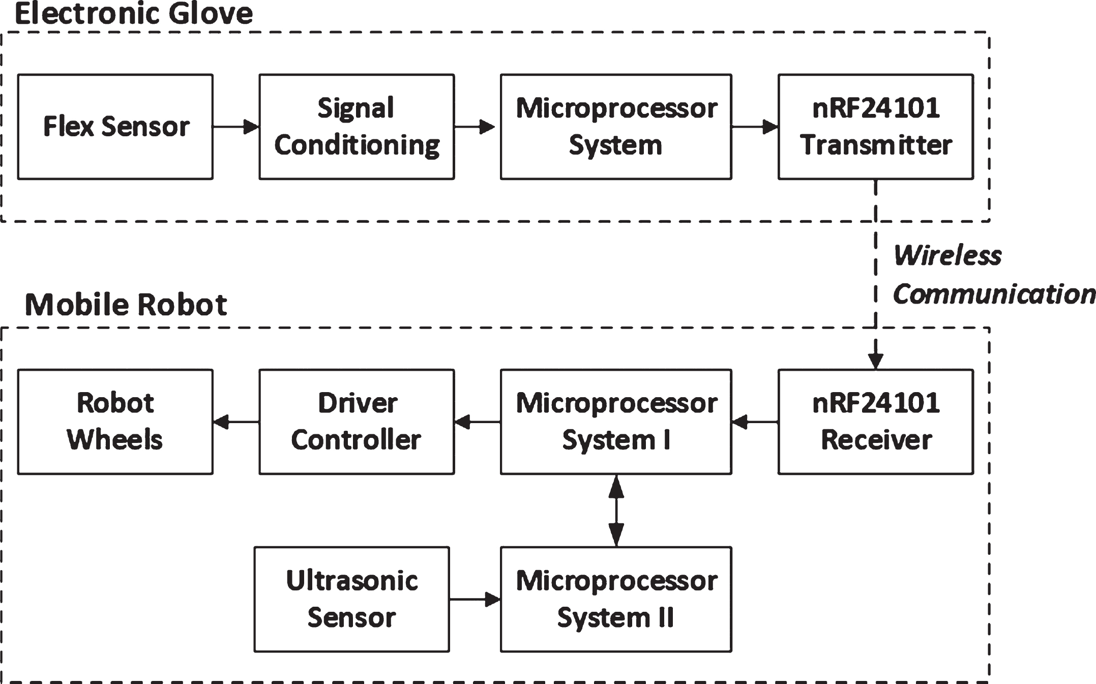
Block diagram of system.
In the Microprocessor System, the signal conditioner output is processed using fuzzy logic and transmitted to Microprocessor System I in the mobile robot unit. Data are sent wirelessly using the radio frequency module nRF24l01. Microprocessor System I controls the mobile robot wheels, allowing it to move according to the command from the electronic glove.
Microprocessor System II on the mobile robot unit obtains input from the ultrasonic sensor to obtain information about the distance between the front of the mobile robot and an obstacle. When the distance between the front of the mobile robot and the detected object is smaller than the specified safe limit, then Microprocessor System II sends a signal to Microprocessor System I in order to perform braking and prevent it going forward while the detected distance is still near or below the specified limit. Microprocessor System II also functions as a data logger.
Finger motion configurations must be designed to determine the five finger combinations that form the commands for the mobile robot: forward, backward, forward left, forward right and stop. The finger configurations for mobile robot commands can be seen in Fig. 2.
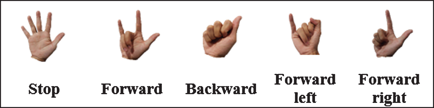
Finger motion configurations.
Fuzzy logic control was chosen in this study because in electronic glove there are five flex sensors whose output must be processed to produce commands to the mobile robot. Although the five flex sensor output processing can use the on-off control, the mobile robot movement is not as smooth as using fuzzy logic.
There are three input variables and two output variables, as shown in Fig. 3. The input variables consist of the thumb and index finger, middle finger and ring finger, and little finger. The output variables consist of the speed of the left wheel and the speed of the right wheel.
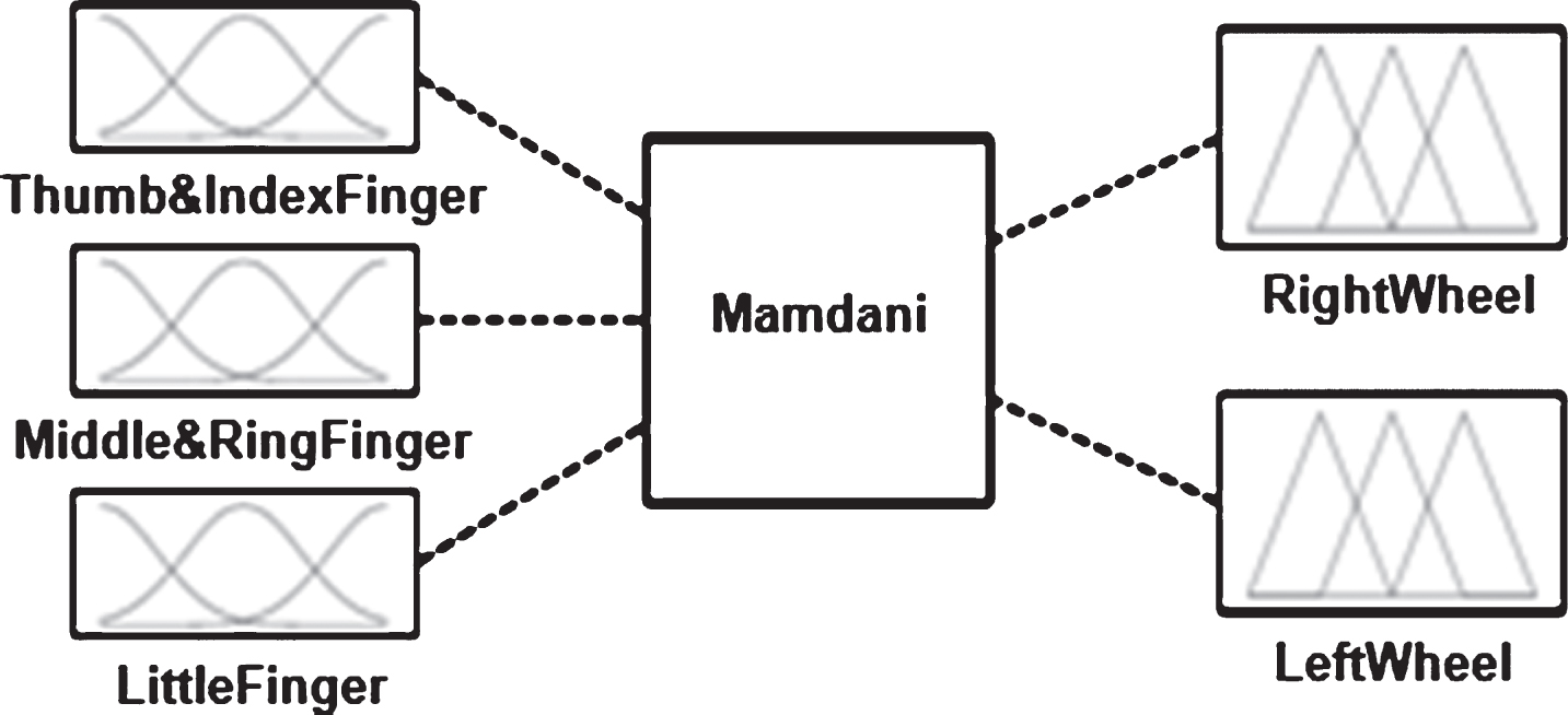
Design of fuzzy logic controller.
The input membership functions can be seen in Figs. 4–6, while the numerical range of linguistic variable for inputs can be seen in Table 1. The membership functions and numerical range of linguistic variable for ouput can be seen in Figs. 7, 8 and Table 2. Membership functions for left and right wheel speed are identical.
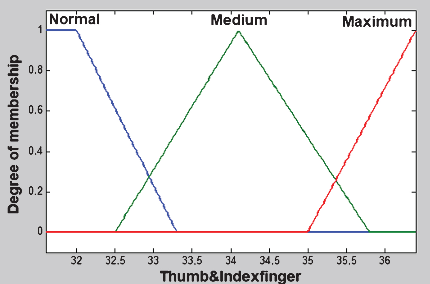
Membership function of thumb and index finger.

Membership function of middle finger and ring finger.
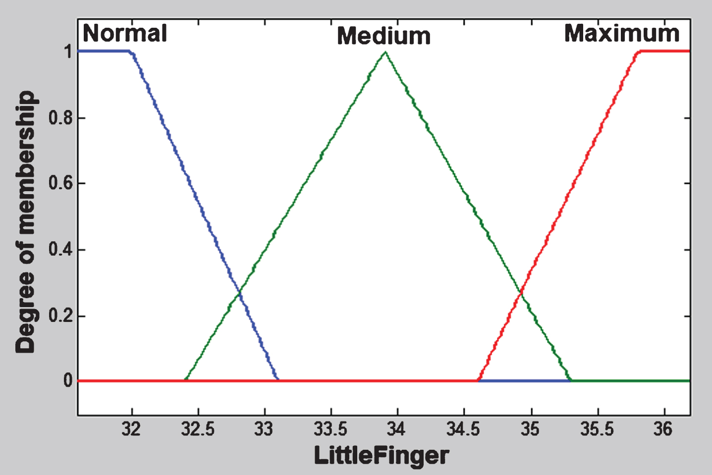
Membership function of little finger.
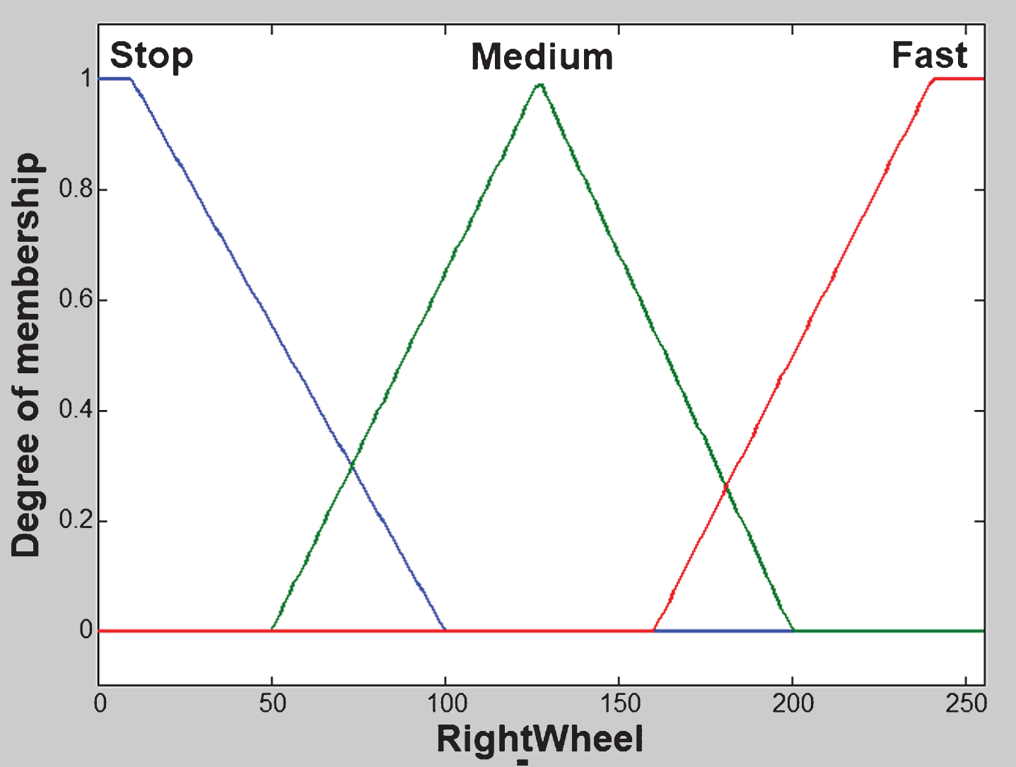
Membership function of right wheel.
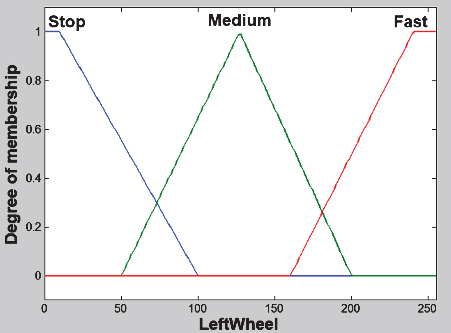
Membership function of left wheel.
The Fuzzy Associative Memory (FAM) tables can be seen in Tables 1–3.
Numerical range of linguistic variable for inputs
Numerical range of linguistic variable for inputs
FAM for normal little finger
LW = left wheel, RW = right wheel, S = stop, M = medium, F = fast.
FAM for medium little finger
LW = left wheel, RW = right wheel, S = stop, M = medium, F = fast.
FAM for maximum little finger
LW = left wheel, RW = right wheel, S = stop, M = medium, F = fast.
The electronic glove was made using a motorized glove fitted with a flex sensor on each finger segment. Electronic systems are mounted on the back of the hand. The electronic glove realization can be seen in Fig. 9.
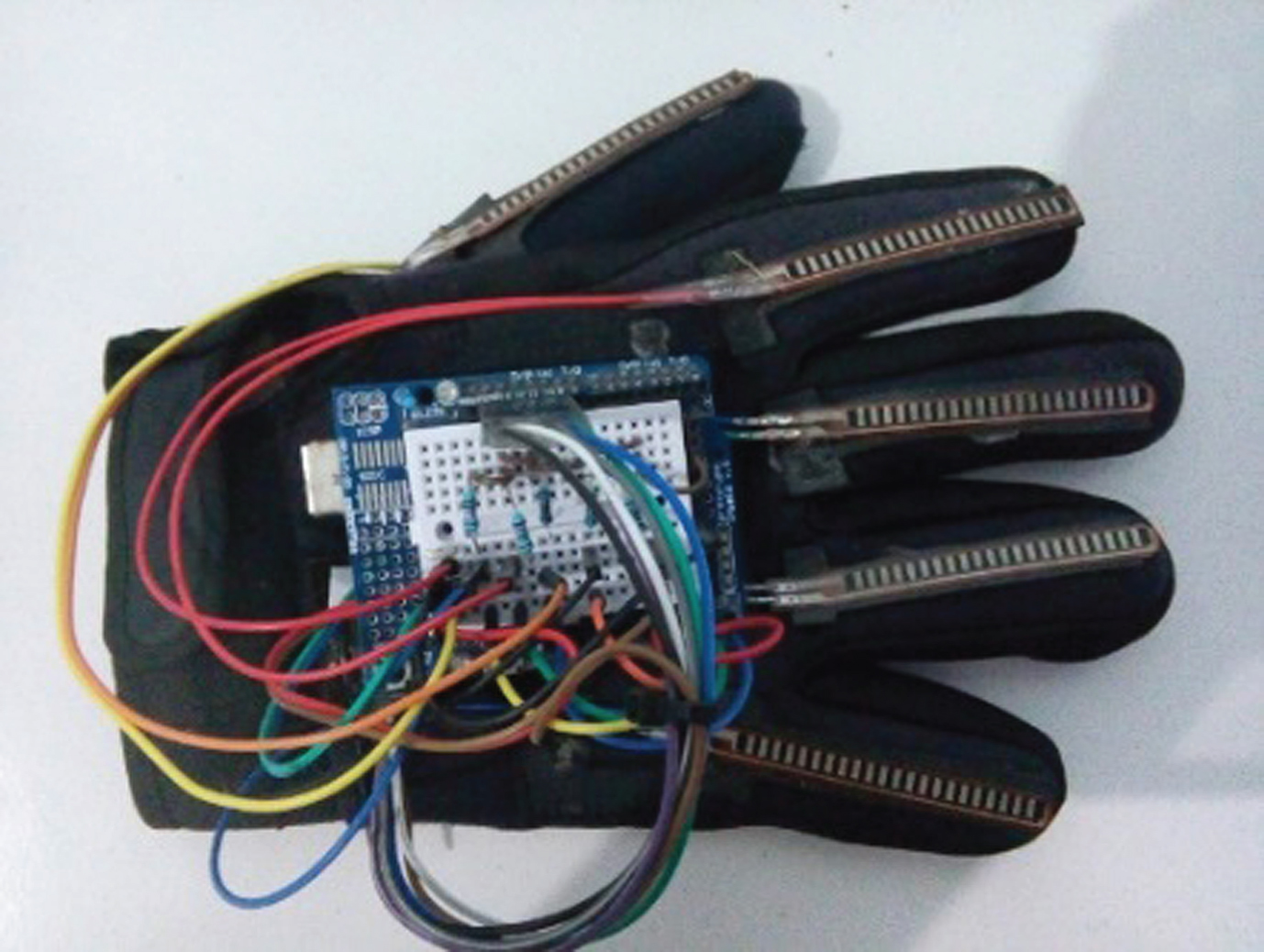
Realization of electronic glove.
The mobile robot in this study is made of acrylic material with a thickness of 3 mm. Fig. 10 shows the realization of the mobile robot.

Realization of mobile robot.
The test is performed in two stages: the influence of each finger on the speed of the mobile robot wheels and whole-system testing to move the mobile robot. The first test involves comparing the analogue values of the flex sensor with the speed of the left and right wheels of the mobile robot. A second test observed the effect of a fuzzy logic algorithm compared to an if-else algorithm.
Thumb response testing
For thumb testing, the condition of the index finger, middle finger and ring finger is a medium bend of 45° and the little finger is in a normal condition. This is done so that when the thumb is bent, the command given is to turn left, so there is output relating to both left and right motor speeds. The thumb test results can be seen in Fig. 11.
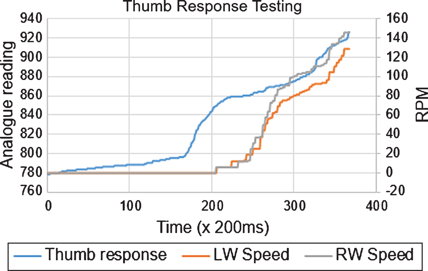
Test result from thumb response testing.
Figure 11 shows that the change in resistance of the thumb is followed by a change in the speeds of the left and right motors. The speeds of the left and right motors look almost the same when the command is to turn left. This is due to the different polarities of the right motor (forward) and the left motor (backward).
In the index finger test the condition of the thumb, middle finger and ring finger is a medium bend of 45° and the little finger is in a normal condition. This is done so that when the index finger is bent, the command given is to turn left, so there is output relating to both left and right motor speeds. The test results for the index finger can be seen in Fig. 12.
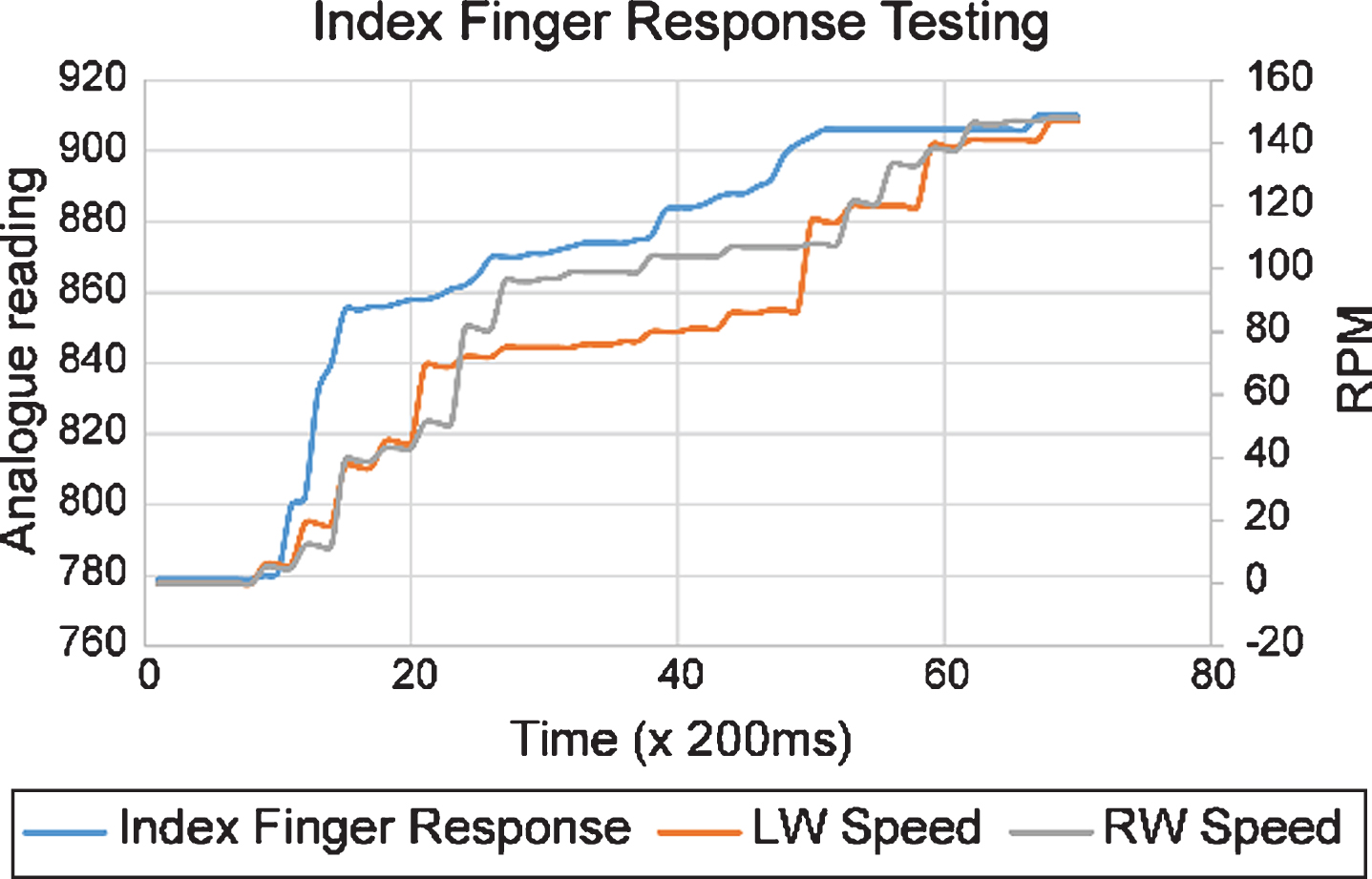
Test result from index finger response testing.
From Fig. 12, it appears that the change in resistance of the index finger is followed by a change in left and right motor speeds. The change in the resistance of the index finger is considerably more significant than that of the thumb because the index finger is more flexible in bending than the thumb.
The test for the middle finger is performed by adjusting the thumb, index finger and little finger to the condition where they are not bent and bending the ring finger and the middle finger. This is done so that when the middle finger is bent, the command given is to move forward, so that there is output relating to both left and right motor speeds. The test results for the middle finger can be seen in Fig. 13. From Fig. 13 it appears that the change in resistance of the middle finger is followed by a change in left and right motor speeds.

Test result from middle finger response testing.
The ring finger test is performed by adjusting the thumb, index finger and little finger to the condition where they are not bent and bending the middle finger along with the ring finger. This is done so that when the ring finger bends, the command given is to move forward, so there is output relating to both left and right motor speeds. The test results for the ring finger can be seen in Fig. 14.

Test result for ring finger response testing.
Figure 14 shows that the change in resistance of the ring finger is followed by a change in left and right motor speeds. The change in motor speed produced is smoother as the speed gradually increases on bending the finger.
The little finger test is performed by adjusting the condition of the thumb and index finger so that it is not bent and setting the middle finger and ring finger to a bending condition of 45°. This is done so that when the little finger is bent, the command given is to turn right, so there is output relating to both left and right motor speeds. The test results for the little finger can be seen in Fig. 15.

Test result from little finger response testing.
From Fig. 15, it can be seen that the change in resistance of the little finger is followed by a change in left and right motor speeds. In the interval between 2 s and 8 s, there is a noticeable change in velocity, although the change in resistance is not significant. This occurs because in the right-turn command, it is not only the input of the little finger that produces a change of velocity; the middle finger and ring finger also affect the speed change, so that when the condition of the middle finger and ring finger is constant at 45°, a small change from the little finger will greatly affect the mobile robot speed change. Just as in the test for the thumb and index finger, the speeds of the left motor and right motor are almost identical but the motors have different polarities.
Motion testing without a fuzzy logic controller was performed using an if-else algorithm on the mobile robot for the determination of the motion. The if-else algorithm uses limit/threshold parameters for determining the motion. Test results can be seen in Fig. 16. It can be seen that the change in sensor resistance does not directly correspond to the speed of the robot car wheel. This is because the if-else algorithm uses strict limits in the determination of the motion.

Motion test result using if-else algorithm.
Motion testing with fuzzy logic was performed using a fuzzy logic controller algorithm for determining the motion. The test results can be seen in Fig. 17.
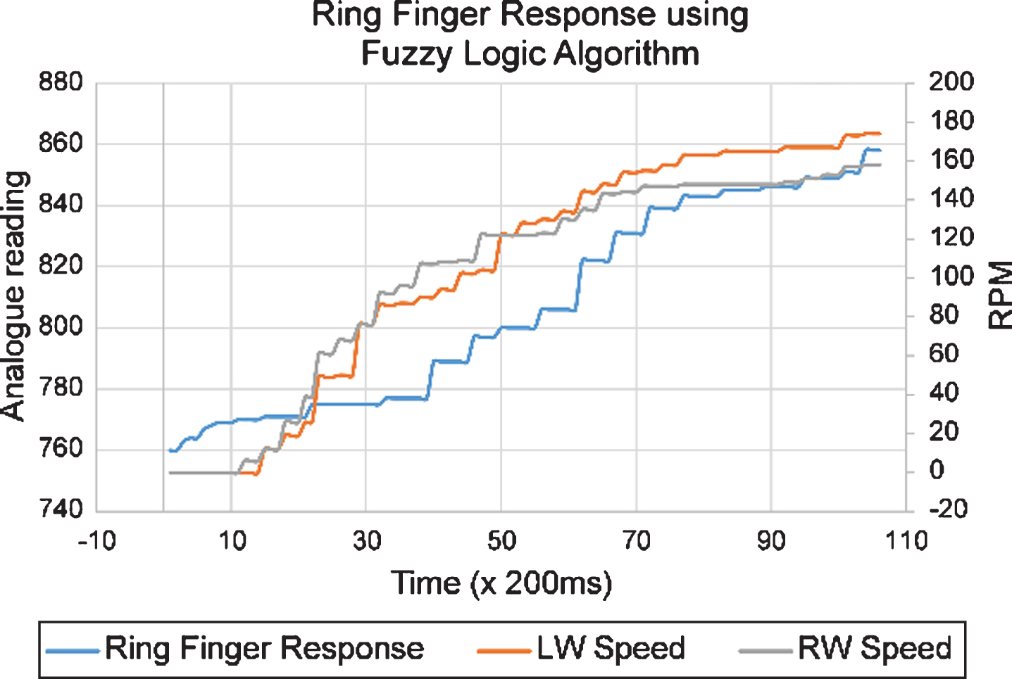
Motion test results using fuzzy logic.
Figure 17 shows the relationship between the speed of the left motor and that of the right motor with bending of the ring finger in a 200-ms time interval. It appears that with the application of a fuzzy logic controller, the electronic glove allows the mobile robot to achieve higher speeds.
Changes in finger resistance are followed by mobile robot speed changes. In the time interval between 1 s and 10 s, significant finger bending is performed. The bending changes are then followed by changes in mobile robot speed. In contrast to Fig. 16, which shows the application of if-then logic, there is a threshold that results in a constant mobile robot velocity even when finger-bending changes occur. Thus, with the fuzzy logic controller application the variations in values between the medium speed threshold and the maximum speed threshold show varying outputs and the mobile robot motion becomes smoother.
Flex sensors are capable of varying output values between normal conditions of 27.2 kΩ to a maximum of 46 kΩ. The success rate for the movement generated by the mobile robot as a result of the given command was 100%. This means that there was no motion error resulting from the given commands. The ability of the electronic glove to use a fuzzy logic algorithm for mobile robot control leads to better results than those obtained by using an if-else algorithm. This is shown by its sensitivity in following the finger bending changes when used to control the mobile robot.