
Abstract
If robot uses 2D lidar or binocular camera to locate obstacles, there will be some problems such as missing obstacle information or inaccurate obstacle locating, which will affect the normal work of the robot. In order to obtain accurate 3D obstacle information, this paper proposes an algorithm for fusing 2D lidar and binocular vision to complete the obstacle location. In this paper, the depth value of the 2D lidar point cloud is used as a benchmark. By fitting the error equation of the binocular camera point cloud depth value, the depth value of the camera point cloud is modified to obtain an accurate 3D camera point cloud, thereby obtaining an accurate 3D obstacle information. Many experiments have proved that the fusion algorithm of 2D lidar and binocular vision can obtain accurate 3D obstacle information. The method of fusion 2D lidar and binocular vision can approximately achieve the measurement effect of 3D lidar, and the point cloud of obstacles is relatively dense, so the accurate 3D obstacle information can be obtained. This method can reduce the influence of single sensor on the robot locating obstacles, thus completing the accurate locating of obstacles, which is of certain significance to robot navigation.
Introduction
The application of mobile robot in daily production and life is more and more widely, and people have more and more research on obstacle location. 2D lidar has the characteristics of accuracy, speed, low price, and is not easy to be interfered [1–4]. However, 2D lidar can only obtain the information of obstacles in the laser beam plane, but not the information of obstacles above or below the laser beam plane [5–7]. For example: 2D lidar can only get the information of the table legs but not the table. The lack of obstacle information will lead to robot collision. Compared with 2D lidar, the binocular camera with the characteristics of high sampling speed and abundant information can obtain the 3D information of obstacles [8–10], but the binocular camera is susceptible to the environment (such as obstacle texture and lighting) [11, 12]. Under the influence of environment and system error, the accuracy of the binocular camera to locate obstacles will be affected. It is difficult for a single sensor to meet the requirements of robots for the perception of complex obstacles [13–15], and multi-sensor data fusion with high precision and strong robustness is increasingly applied in the study of obstacle locating [16–19].
The authors in [20, 21] proposed an adaptive weighted fusion algorithm for multi-sensor information fusion, which weights the measurement information of the camera and radar. This method has high accuracy and wide application range, but has low real-time performance. In literature [22, 23], it is proposed that construct a calibration network and a depth fusion network to complete the depth value estimation. After the joint calibration of radar and camera, the fusion of radar and camera depth value is completed by dilated convolution layer, so as to complete the estimation of depth value. This method has strong real-time performance, but ignores the existence of noise model. When multi-sensor noise exists, the localization effect of this method is poor. Literature [24] proposed that based on the disparity information of the stereo camera, a robust estimator is used to detect obstacles in the 3D world model. The 2D cost map is generated based on the 3D world model, and 2D lidar also generates a 2D cost map. Using the grid based occupation map approach to fuse the obstacle information provided by 2D lidar and stereo camera, the obstacle information can be obtained. Due to the uncertainty of multiple sensors, the accuracy of this method is low under the influence of sensor noise. In order to deal with the uncertainty among multiple sensors, literature [25] proposed to construct the evidential grid maps of lidar and stereo camera respectively. According to the frame of discernment of the evidence grid map, it is judged whether there is an obstacle in the grid, and then the lidar and stereo camera evidence grid map is fused to obtain the obstacle’ s position. This method has the advantages of high precision and can detect dynamic obstacles, but has poor detection effect for arched obstacles. Literature [26] proposed to complete the localization of obstacles by radar and camera through machine learning. The environment feature image is generated from the radar measurement information, and the original camera image and radar environment feature image are fused by semantic fusion to obtain the location information of obstacles. The method has good locating effect on arched obstacles, but the system robustness is poor.
Although the effect of fusion multi-sensor measurement information is better than that of single sensor, the research on fusion of 2D lidar and binocular vision has the disadvantages of poor robustness or low locating accuracy. In view of the above situation, this paper proposes a method to modify the point cloud information of binocular camera by lidar point cloud information. This method has the characteristics of simple, strong robustness and high locating accuracy.
The contributions of this paper are as follows: The error equations of lidar point cloud depth value and binocular camera point cloud depth value is fitted, and the depth value of camera point cloud is modified by the error equation. The modified camera point cloud is accurate 3D obstacle point cloud, which can approximately achieve the measurement effect of 3D lidar. The price of 2D lidar and binocular camera is much cheaper than 3D lidar, so this paper has certain significance in practical application.
The rest of our work is organized as follows. In section 2, We review the ranging principle of camera. In section 3, We propose a method to modify camera point cloud depth by 2D point cloud depth. Experiment results and discussions are provided in section 4. In section 5, we discuss the work of this paper. Finally, conclusions are provided in section 6.
Related work
A typical geometrical setting for stereo vision is shown in Fig. 1. The two cameras on the same plane are parallel to the optical axis. The two camera bases are collinear, and the epipolar lines of the cameras are parallel to the horizontal direction. When the same object is observed, the imaging angle of the object in the two cameras is different, so the position of the object can be calculated according to the disparity of the two cameras [27], and the coordinate information of the obstacle can be obtained.
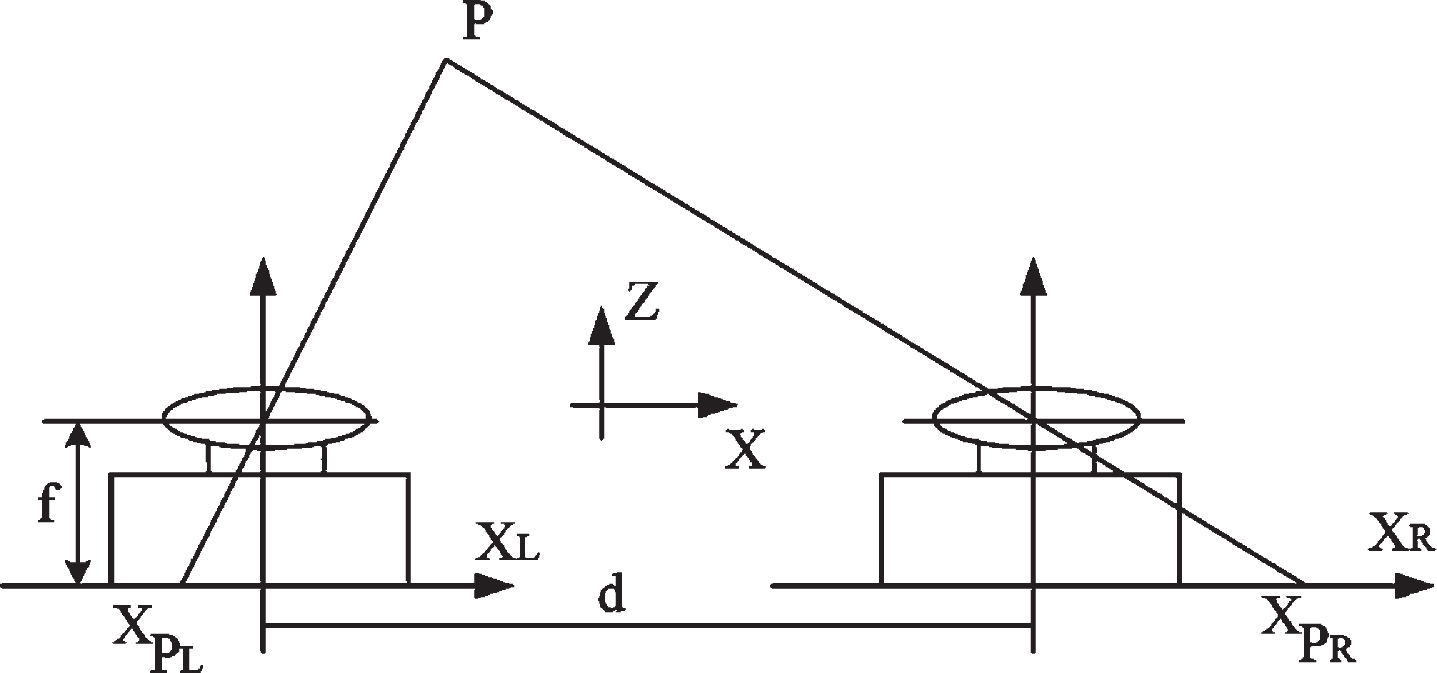
A typical stereo vision geometrical setting.
The relationship between the 3D position information of a point on the surface of a space object and its corresponding point in the image is determined by the camera’s imaging geometric model (camera parameters). In order to get the camera parameters, it is necessary to calibrate the camera. Zhang’s Camera Calibration method [28] is adopted in this paper, which is simple and accurate.
After the calibration of the camera is completed, the intrinsic matrix of the camera can be obtained. It is known from the literature [29, 30] the transformation relationship between the object in the world coordinate system and the camera coordinate system is shown as Equation (1), thereby obtaining the 3D coordinates of the object.
Where ZC is the focal length of the camera, (U, V) is the coordinate of the object in the sensor coordinate system,
Figure 2 shows the process of robot fusion 2D lidar and binocular camera to complete obstacle locating. Because the measurement error of binocular camera mainly exists in the depth direction, the errors of binocular camera point cloud in the horizontal and vertical directions are ignored in this paper. The method of 2D lidar point cloud modification camera point cloud is as follows.

The process of robot fusion 2D lidar and binocular camera to complete obstacle locating.
Step (a): filter the camera point cloud
In the robot coordinate system, the vertical coordinate of the 2D lidar point cloud plane is h, and the 2D camera point cloud plane with the same height is taken for processing. Take any lidar point i from the 2D lidar point cloud plane and mark its coordinate as (Ai, Bi). In the horizontal interval [Ai-Δj, Ai+Δj], take the camera point g with the minimum Euclidean distance from the lidar point i as the selected camera point. If the camera point is missing in the horizontal interval [Ai-Δj, Ai+Δj], then the corresponding camera point is missing from the lidar point. Δj can be expressed as:
Where r and Δθ are lidar scanning radius and lidar scanning angle respectively.
Perform the above operations for each lidar point. For any lidar point i, if there is a corresponding camera point, the lidar point is marked as lidar point array E, and the coordinates are marked as (Am, Bm). Otherwise, the lidar point is marked as lidar point array F, and the coordinates are marked as (An, Bn).
Step (b): Interpolation of camera point cloud
Sometimes binocular camera is affected by the system error and the environment (such as obstacle texture and lighting), resulting in the lack of camera point cloud [32, 33]. In order to ensure that there are enough camera points to fit the error equation of camera point cloud depth value, it is necessary to interpolate the camera point cloud.
In order to improve the accuracy and real-time performance of the algorithm, the nonlinear quadratic fitting method is used to interpolate the camera point cloud. It is known from step (a) that the lidar point in the lidar point array F does not have a corresponding camera point, and a lidar point p is arbitrarily taken from the lidar point array F with coordinates (An, Bn). Three lidar points are selected from the lidar point group E which the absolute difference between the depth value of the three lidar points and the depth value Bn of lidar point p is the minimum. It is known from step (a) that each lidar point in the lidar point array E has a corresponding camera point, and the camera points corresponding to the above three lidar points are respectively marked as the camera point q (Cq, Dq), the camera point s (Cs, Ds), and the camera point t (Ct, Dt). The interpolation equation of camera point cloud is as follows:
Where x and f (x) represent the horizontal coordinates and depth values of the camera point, respectively. By substituting (Cq, Dq), (Cs, Ds), and (Ct, Dt) into Equation (3), it can be expressed as:
Equation (4) can be expressed as follows:
Assuming ,
Equation (3) can be expressed as follows:
The horizontal coordinate of the camera point to be interpolated can be approximately considered to be the same as the horizontal coordinate of the corresponding lidar point. The depth value Dn of the camera points to be interpolated can be obtained by substituting the horizontal coordinates An of lidar points into Equation (7), so that the coordinates of the camera points to be interpolated are (An, Dn). The same method is used to interpolate the missing camera points.
Step (c): Modify the camera point cloud depth value
The interpolation of camera point cloud is completed by step (b), and each lidar point has a corresponding camera point. The coordinates of lidar point cloud and camera point cloud are marked as (Ay, By) and (Cz, Dz) respectively. The depth value By of each lidar point and the depth value Dz of corresponding camera point constitute an array (By, Dz). The observation values of array (By, Dz) are (B1, D1), (B2, D2), ... , (Ba, Da), ... , (Bb, Db), where the number of lidar points is b,1≤a≤b. Because 2D lidar points are few and concentrated in the position of obstacles, the observed values are relatively concentrated. Therefore, nonlinear quadratic fitting error function is used to fit the error equation of camera point cloud depth value. The error equation is as follows:
Where, c, d, and e are the best estimates of Equation (8). Assume the difference between the observed value Ba and the theoretical value
Derivative of c, d, and e can be obtained as follows:
When
Assuming ,
Equation (8) can be expressed as follows:
The depth values of all camera point clouds are substituted into Equation (13), and the depth values of all camera point clouds can be modified by Equation (13), so as to complete the modification of camera point clouds.
Verification experiment
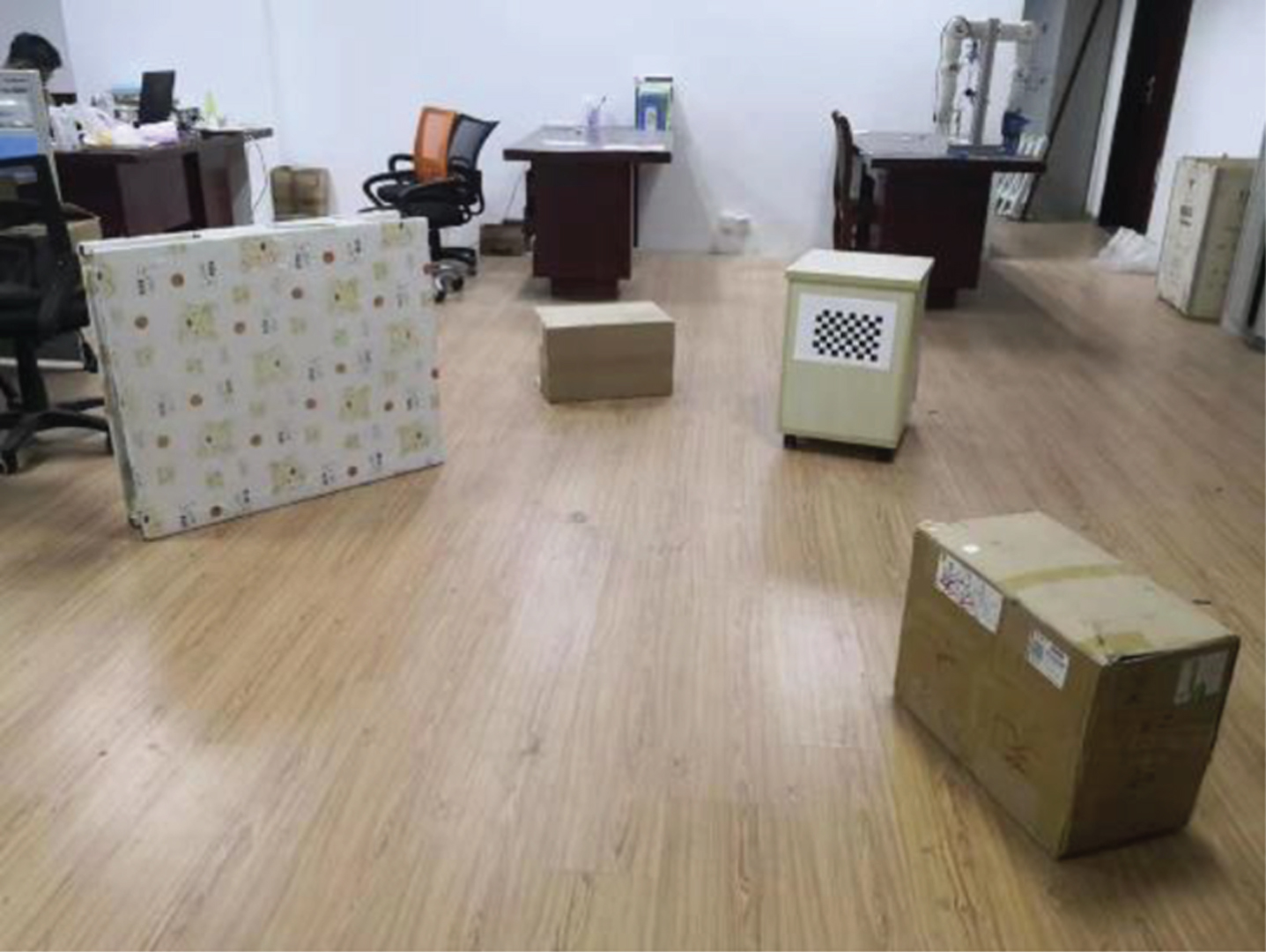
Use the binocular camera to complete the image collection of the random obstacle scene as shown in Fig. 3 to obtain a 3D binocular camera point cloud. In section 3, the method of using 2D lidar point cloud depth value to modify the point cloud depth value of binocular camera is proposed. In this section, obstacle point clouds with horizontal coordinate interval [–1000 mm, 1500 mm] and depth coordinate interval [0, 4000 mm] are selected to verify the method.
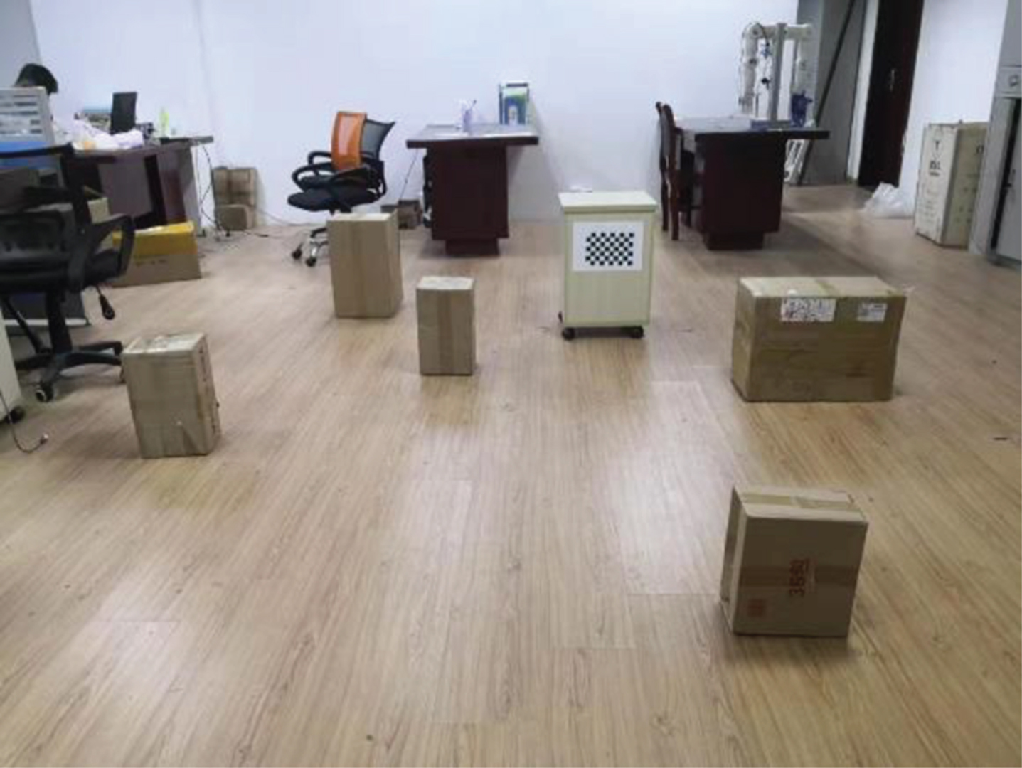
Random obstacle environment.
Take the 2D camera point cloud plane with the same height as the 2D lidar point cloud plane. All camera points are filtered by step (a) in Section 3, and the camera point cloud matching the lidar point cloud is selected. The filtered camera points are shown in Fig. 4.
Filters the camera point cloud.
After the camera point cloud is filtered, the missing camera point cloud needs to be interpolated, and the missing camera point cloud is interpolated by the equation f(x) = G1·H·x2+ G2·H·x+ G3·H. The camera point cloud after interpolation is shown in Fig. 5. After the interpolation of the missing camera point cloud is completed, the camera point cloud depth value is modified by the error fitting equation
Camera point cloud after interpolation.

Modified camera point cloud.
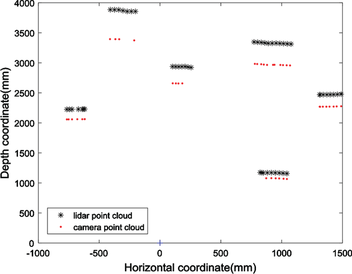
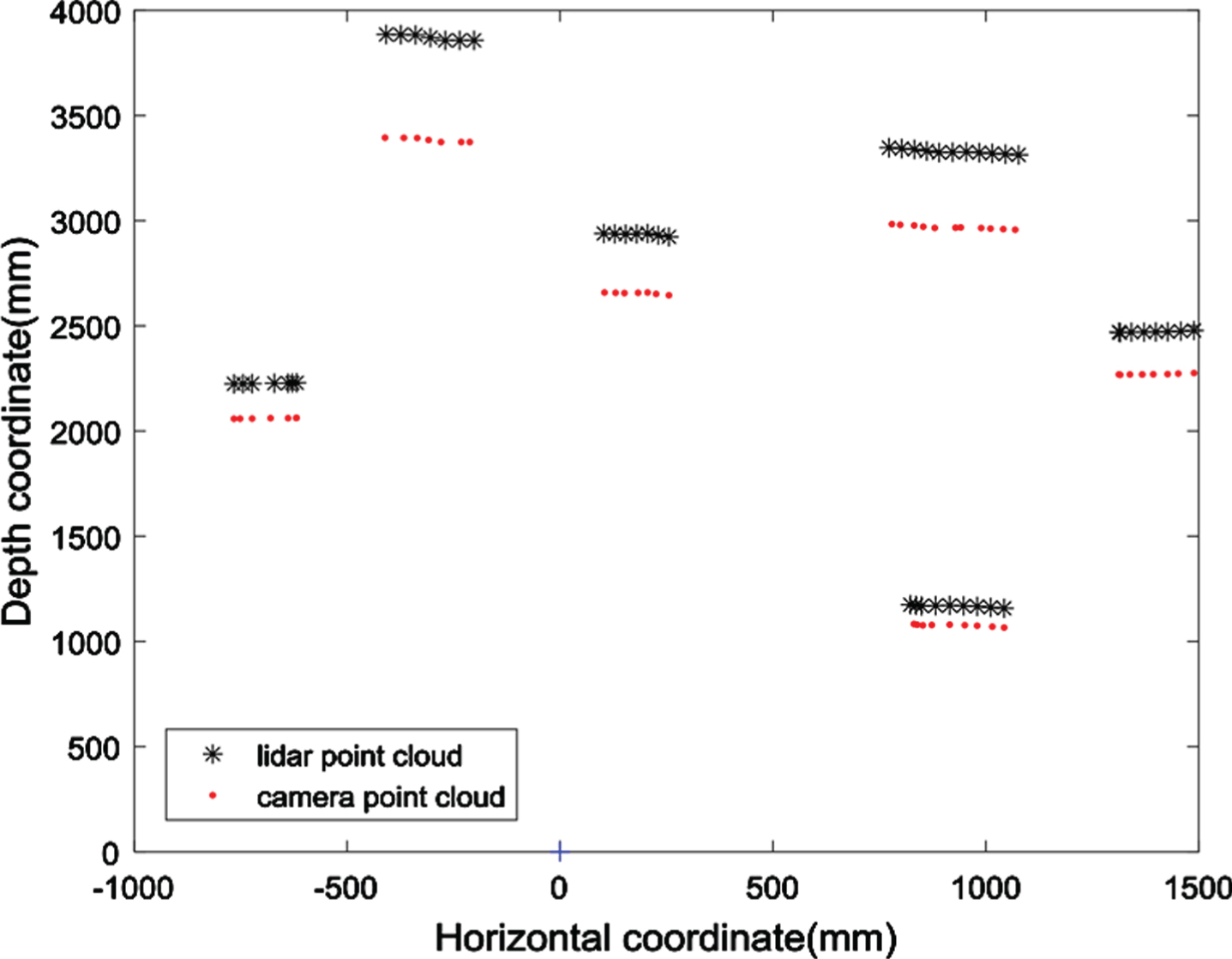
Different experimental scenes are randomly arranged for many times. Figure 7 shows one of the random experimental scenes. The robot collects obstacle information by binocular camera and lidar, and uses lidar point cloud depth information to modify the binocular camera point cloud depth information. Fig. 8 shows the lidar point cloud and the modified camera point cloud. After several experiments, the average error of the camera point cloud depth value without modification and after modification was recorded. The experimental results are shown in Fig. 9. It can be seen from the experimental results that the modified point cloud error is small.
Experimental environment.

Lidar point cloud and modified camera point cloud.
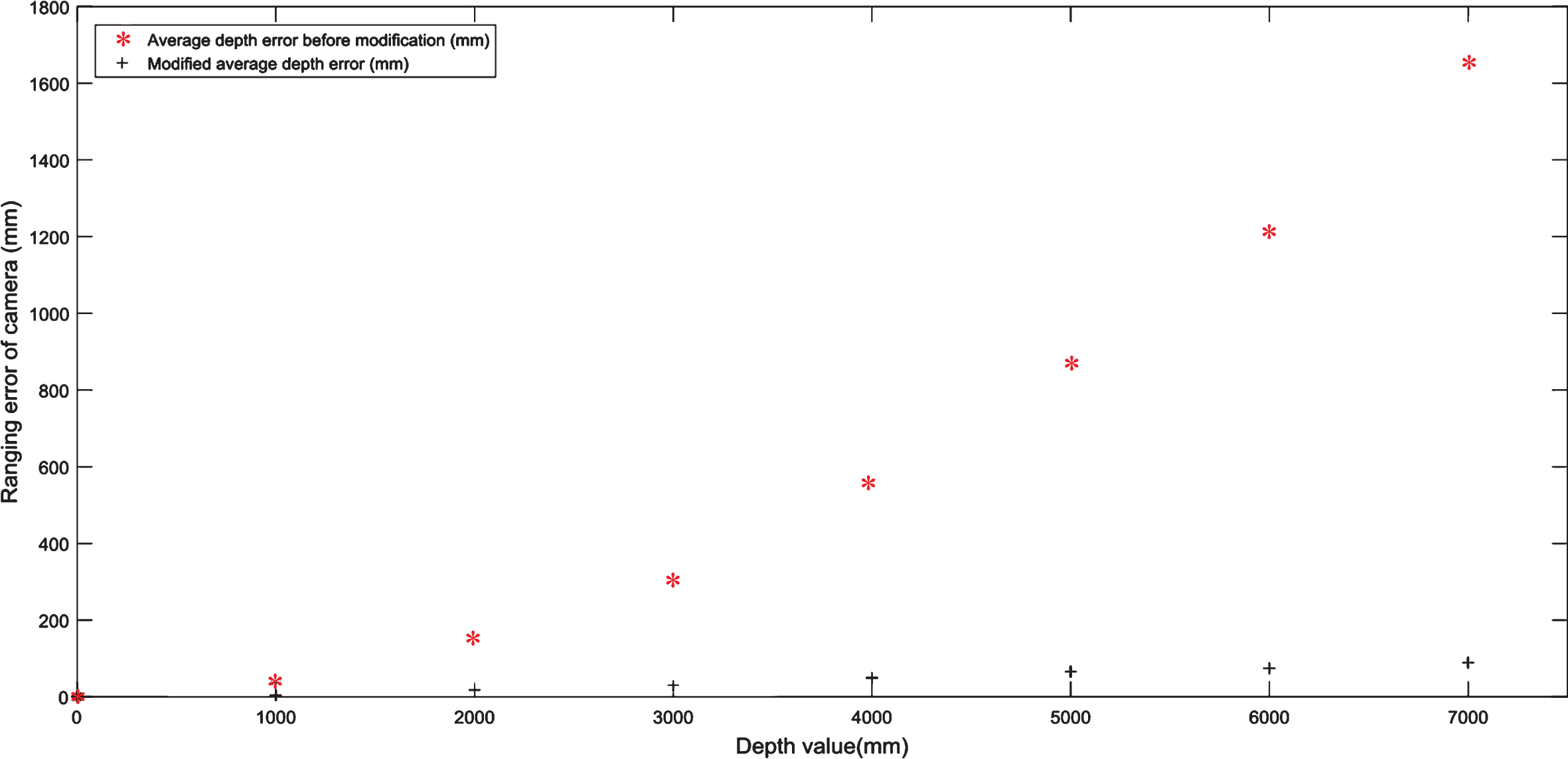
The average error of the camera point cloud depth value without modification and after modification.
It can be seen from the experimental results in section 4 that the error of binocular camera point cloud modified by 2D lidar point cloud is small, and the accurate 3D obstacle information can be obtained by fusing 2D lidar and binocular vision. Compared with literatures [22, 23], the error of radar point cloud can be ignored, and the depth value of camera point cloud is modified by the depth error function of camera point cloud based on the depth value of radar point cloud, so the influence of binocular camera noise can be ignored in this paper. In this paper, the accurate 3D obstacle point cloud information is obtained by modifying the binocular camera point cloud. Therefore, compared with literature [25], this paper also has a better effect on the location of arch obstacles. Compared with literature [26] the algorithm has strong robustness and wide application range.
Fusion of 2D lidar and binocular camera to locate obstacles can approximately achieve the measurement effect of 3D lidar. In this paper, accurate 3D obstacle information can be obtained by using low-cost binocular camera and 2D lidar, so this paper has certain practical value.
Conclusion
The accuracy of sensors is important for mobile robots, and there are some disadvantages when using one sensor alone. Therefore, there are more and more researches on multi-sensor obstacle location. The method of fusing camera point cloud and 2D radar point cloud proposed in this paper completes the locating of obstacles. The principle of this method is to filter the camera point clouds that match the radar point clouds, and the function between camera point cloud depth value and radar point cloud depth value is fitted, so as to correct the depth value of the binocular camera point cloud. The modified camera point cloud is an accurate 3D camera point cloud.
By fusing 2D lidar and binocular vision, accurate 3D obstacle information can be obtained. Compared with 3D lidar, 2D lidar and binocular camera are cheap, but the fusion of 2D lidar and binocular vision can get the effect similar to 3D lidar, which has certain practical value. In the following research, we will apply the fusion algorithm of 2D lidar and binocular vision to robot navigation.