
Abstract
Regenerative braking system is a system by which an energy conversion device is used to convert kinetic energy into electrical energy and store it in an energy storage device for use when the motor vehicle is driving. To improve the energy recovery rate of pure electric vehicles, a series regenerative braking control strategy based on PMSM fuzzy logic is proposed in this paper. According to this strategy, the motor braking shall be used as much as possible based on ensuring braking stability, 4 braking zones shall be divided according to the braking intensity, and different braking force distribution strategies shall be used, while comprehensively considering influencing factors such as vehicle speed, ECE regulations, battery, and motor characteristics. Simulink and Cruise are used for modeling and united simulation. The results show that the built model is accurate and reliable. The energy recovery rate can be improved effectively and the cruising range of pure electric vehicles can be extended based on proposed series regenerative braking control strategy.
Introduction
The regenerative braking system can be used to convert kinetic energy into electrical energy by using energy conversion device and store it in an energy storage device for use when the vehicle is driving, so as to realize the recycling of energy to achieve the purpose of extending the cruising range and provide a certain torque for braking [2, 11]. The regenerative braking systems mainly have two types: parallel and series: parallel regenerative braking is to superimpose part of the electric mechanism power based on the original mechanical braking, with the characteristics of low cost and small changes, which is currently widely used; series regenerative braking is to use the motor for braking first coupling the mechanical brake and the motor brake. When the required braking force is large and the single regenerative braking cannot meet the braking demand, the mechanical braking system will only work, maintaining the braking state while completing regenerative braking [1, 10].
When a vehicle is driving in a city, the energy consumed by braking accounts for a large proportion. Although the braking energy cannot be fully recovered, the final recovered energy is very considerable. How to distribute braking torque reasonably and recover as much braking energy as possible on the basis of ensuring the safety and smoothness of vehicle braking has always been the most critical issue of regenerative braking system [12–15].
Aiming at a front-drive pure electric vehicle, a series rechargeable vehicles regenerative braking control strategy is proposed based on PMSM fuzzy logic, comprehensively considering a variety of influencing factors to reasonably distribute the braking torque in this paper and on the basis of satisfying braking stability the regenerative braking of the motor is used as far as possible to improve the energy recovery rate. Modeling and simulation analysis verify the correctness of the control strategy.
Distribution of braking force
Ideal braking force distribution between front and rear wheels
When braking, the front and rear wheels are locked at the same time, which can make better use of road adhesion conditions and improve the directional stability of the vehicle during braking. The ideal distribution curve of front and rear wheel braking force (I curve for short) satisfies:
Where: Fμ1 and Fμ2 are the front and rear wheel braking forces, respectively, N; b is the distance from the center of mass of the vehicle to the rear axle, m; L is the wheelbase, m; hg is the height of the center of mass of the vehicle, m; G is the gravity of the vehicle, N.
The clear requirements for the front and rear wheel braking force of M1 vehicles are proposed in the European Economic Committee(ECE) braking regulation: when braking on a road with a road adhesion coefficient of 0.2 to 0.8, the braking strength is required to be
Available ECE regulatory limit curve (referred to as M curve):
The road adhesion coefficient determines the maximum braking force that the ground can provide. Braking on a road with a road adhesion coefficient of φ, the front and rear braking force relationship is as follows when the rear wheel is not locked and the front wheel is locked:
In daily life, vehicle s drive most of the time between the urban area and the suburbs. The congested traffic conditions result in low speed and frequent braking. Most of the braking conditions belong to low-to-medium-intensity braking (z≤0.2), and z≤0.1 occurs in more than 75% of them. In order to maximize the recovery of energy, motor braking should be used as much as possible when braking at medium and low intensity. When the front wheel is not locked and the braking stability is satisfied, the front wheel braking shall be used as much as possible, as well as motor braking force. Mild braking (z≤0.1, OA) is completely dependent on motor braking. It is manifested as a long-term charging with a small feedback current, and the main limiting factor is the state of charge (SOC) of the battery. Moderate braking (0.1 < z≤0.5, AB) is an electromechanical hybrid brake. AB is the tangent of the M curve and is used to increase the proportion of the front wheel braking torque distribution as much as possible on the basis of meeting the ECE braking regulations to improve the braking energy recovery rate. Heavy braking (0.5 < z≤0.7, BC). At this time, the braking intensity is greater. To ensure braking stability, the proportion of rear wheel braking torque should be further increased. This braking zone is a transition zone from priority in braking energy recovery to priority in braking stability. Emergency braking (z > 0.7, CD) is usually an abrupt and high-intensity braking condition when a vehicle is in a dangerous situation. Considering safety, the regenerative braking system should be turned off at this time and mechanical braking shall be relied on.
Among the 5 types of working modes of series hybrid electric vehicles, the three working modes of common driving mode, charging while driving and parking while charging involve the work of the auxiliary power unit APU. Three main working functions of APU are determined according to the five working modes of series hybrid electric vehicles, combined with the comprehensive consideration of engine operating performance and emission performance: The engine is started to a higher idle speed state by startup function, which mainly serves as a heat engine. When the cooling water temperature reaches the set value, the engine speed is increased to make it work in the high-efficiency and economic working range. Constant speed function After the engine is warmed up, it will quickly increase to the set speed, so that the engine can run stably and at a constant speed in a high-efficiency economic working area. The throttle opening changes with load to ensure stable engine speed, and only adjust within a small range without major changes, so as to ensure that the engine’s oil consumption and emissions are minimized. Shutdown function When the remaining power of the storage battery exceeds a given value, the engine runs abnormally (for example, the cooling water temperature is too high), and human factors need to be changed to pure electric operation or shutdown, the engine shall be shut down.
The performance of the APU, especially the engine, has a huge impact on the power, economy and emissions of the vehicle. In the study of series hybrid electric vehicles, optimal control of APU is the key to achieving the target of low oil consumption and low emission for hybrid electric vehicles. On the premise of meeting the requirements of vehicle power and other basic technical performance and cost, the purpose of the control strategy is to realize the reasonable and effective distribution energy of the energy between the APU, the drive motor and the power battery pack, maximize the efficiency of the entire vehicle system, while ensuring vehicle power performance, low emissions, and optimal fuel economy in terms of the operating conditions of hybrid electric vehicles.
Modeling of unit control system fused with PMSM fuzzy logic
Model of auxiliary power unit control system fused with PMSM fuzzy logic
The auxiliary power unit control system controls the operation of the APU according to signals such as the power battery pack SOC, APU cooling water temperature, charging current, charging voltage and engine speed. Specifically, the operation of the engine is controlled, the generator to generate electricity is driven, and the power battery pack is charged.
The main functions of the APU controller are: APU start and shutdown control; High idle speed heat engine; Steady-state speed control of engine.
Start and shutdown control of the engine: When the SOC of the battery drops below the SOCmin value, it is determined whether the engine can be started according to the APU cooling water temperature and the engine speed signal at this time. Once the conditions meet the starting requirement, the engine is started by APU controller starting control signal and outputting high level for starting motor. After the engine is started, when the engine speed rises to the value that the engine can operate normally, the controller will start the control signal and output a low level. When the SOC of the battery rises and exceeds the SOCmax value, the engine is shut down. At the same time, in consideration of the safe operation of the APU, the temperature of the cooling water during the operation of the APU shall be monitored. Once the cooling water temperature exceeds the set safe value, the APU controller outputs a stop signal to stop the engine.
High idle speed heat engine: in order to protect the engine, after the engine is started for the first time or when the cooling water temperature of the engine is lower than the set value, the engine shall be warmed up at idle speed for a certain period of time. The idling speed is higher than the speed of the vehicle at normal idling, because the purpose of idling is only to heat engine. The engine’s high idle speed heat engine is mainly realized by judging the engine’s water temperature. In the control program, the adjustable heat engine temperature value is set. When the engine’s water temperature is lower than the set value at which the engine can work normally at the initial stage of engine operation, the throttle output is controlled to make the engine run in a high idle state. As the engine runs, the water temperature of the engine rises, and when it exceeds the set value, the engine speed is allowed to rise to the target speed of the working economic zone.
Control of the engine speed: When the charging conditions are met, the throttle output is controlled, and the engine speed is quickly increased to the speed value of the set economic working area, and the power battery is charged. Because the charging current can reflect the power required by the vehicle. The target speed of engine operation changes with the change of charging current. When the target engine speed is determined, a certain speed control method is used to control the speed to be constant. When the APU speed is greater than the target value, the throttle output is reduced to lower the speed. When the engine speed is less than this value, the throttle output and speed shall be increased. When the battery SOC rises to a certain value or the cooling water temperature exceeds the set maximum warning line, the speed shall be lowered or the engine is shut down.
The APU controller includes three control sub-modules: start control, speed control, and shut down control. It can also protect the APU. It is mainly realized by controlling the engine speed according to the cooling water temperature of the engine. When the APU cooling water temperature is too low, a high-idle heat engine shall be performed for a certain period of time. When the APU cooling water temperature is too high, the speed shall be reduced or the engine be shut down to reduce the charging current.
Starting control sub-model fused with PMSM fuzzy logic
The starting control sub-model determines the starting time and working time of the starting motor. Starting control conditions: When the power battery pack SOC < 0.2, the engine speed n is less than 100 rpm, which is deemed that the engine has not started, then the starter motor shall be controlled for start; When the speed is 100 < n<800 rpm, the starting state shall be kept, or the engine shall be started once again; When continuous starting occurs, the start shall be controlled at a certain interval each time. The starter motor is started thrice continuously, and the speed n < 800 rpm, which is considered that the engine has not started, the starting process shall be suspended. If you still want to start the motor, you need to manually re-power on.
Figures 3–9 shows the model of starting counter. According to the requirements of the control strategy, the starter motor is allowed to start 3 times continuously. When the motor is started more than 3 times, the control signal of the starting motor is always 0. When the shutdown control signal is 1, the starter motor counter shall be reset and counted again.
Target speed setting sub-model fused with PMSM fuzzy logic
According to the requirements of the APU control strategy, when the SOC value is between 0.2–0.8, the engine is working in the economic working area, the set economic working area is between 2500–3500 rpm of the engine speed.
First of all, after the engine is started, it is determined according to the cooling water temperature whether the engine needs to be warmed up: When the water temperature T < 60 degrees Celsius, high-idle heat engine is performed at 1000 rpm speed: When the water temperature T exceeds 60 degrees Celsius, the speed shall be increased to the pre-set initial speed of 3000 rpm to make the engine work in the economic zone.
The research object of this topic is the permanent magnet synchronous motor used in the APU of the series hybrid medium-sized bus. The characteristic of the permanent magnet synchronous motor is that it does not need excitation control, and is related to the generator speed according to the output voltage of the generator. The APU engine and the generator are coaxially rigidly connected and run at the same speed. The generator output current can directly reflect the output power of the generator. Therefore, the target engine speed of the engine can be adjusted according to the difference between the driving current and the charging current of the driving motor, and the specific adjustment is as follows: If ΔI≤30A, the APU output power shall be considered to be relatively high, and the target value of engine speed is gradually reduced by a difference of 100r/min to reduce the fuel consumption of the engine: If 30< ΔI≤60A, it shall be considered that the APU output power is normal, the engine works in the economic zone, and the engine is running at the previous speed state: If ΔI>60A, it shall be considered that the output power of the APU is slightly small, and the driving demand power is large. The engine speed needs to be increased to increase the output power of the APU, and the target value of the engine speed is increased gradually and steadily with a difference of 100r/min. This situation often occurs when the vehicle is driving at high speed or accelerating or climbing.
Speed control sub-model fused with PMSM fuzzy logic
The traditional engine PI speed control is used to control the engine speed. PI control modeling formula:
According to the APU control strategy, when the power battery pack SOC > 0.8, or the generator current I < IOA and the output voltage U≥400 V, the APU output power is considered to be too low, the load is too small, and the working engine cannot achieve favorable fuel economy. At this time, the engine is required to be turned off and the vehicle runs in pure electric mode. This condition mostly occurs when the state of charge of the battery pack is high and the power demand of the vehicle is small, and the power requirement of the APU is small at this moment. At the same time, for the protection of the APU system, when the abnormality occurs to the engine and the cooling water temperature is higher than 95 degrees Celsius, the engine shall also be shut down immediately. Control Strategy
In the braking process, if the front wheels are not locked, the motor regenerative braking shall be used as much as possible, and the mechanical braking is used only when the braking stability requirements and the legal requirements are met to achieve the maximum energy recovery. The regenerative braking control strategy in this paper is shown in Fig. 2. The central ideas include: Energy recovery is only performed when the vehicle speed V is greater than the minimum vehicle speed Vmin that allows energy recovery. When the vehicle speed is relatively low (V≤5 km/h), the regenerative braking function will fail due to the low back electromotive force of the motor; When the state of charge of the battery is low, the battery is allowed to charge; when the state of charge of the battery is high (SSOC≥0. 95), the battery is forbidden to charge, so as to avoid damage caused by overcharge to the battery life, that is, no braking energy recovery is performed; If the motor can meet the demand for regenerative braking torque, all motor braking is adopted; when the braking torque of the motor cannot meet the braking demand, the mechanical braking system will supplement it; The limitation on the charging power of the different state of charge of the battery must be considered.
Modeling
The basic parameters and power system parameters of the whole vehicle are shown in Table 1.
Main parameters of the simulated vehicle
Main parameters of the simulated vehicle
The Simulink model of serial regenerative braking is compiled into a dynamic link library file (DLL) and embedded in the Cruise vehicle model. The top-level model of the control strategy is shown in Fig. 1. The input vehicle speed, state of charge of battery, accelerator pedal opening, braking pedal opening and motor speed and output motor regenerative braking torque and front and rear wheel mechanical braking torque.
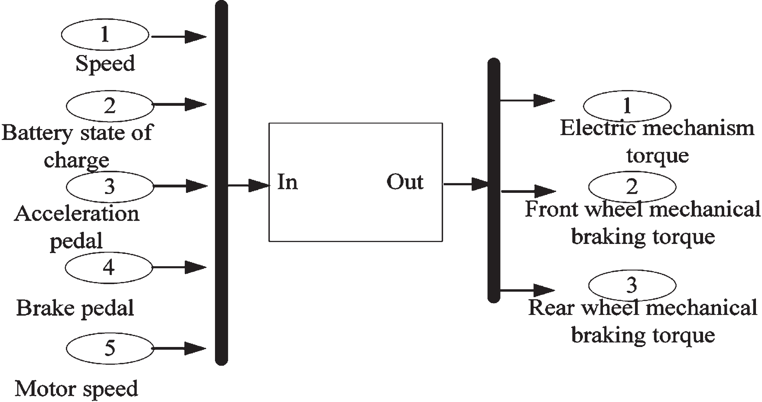
Top-level model of control strategy.
As shown in Fig. 2, according to the braking enabling conditions, it is judged whether to perform energy recovery, meanwhile, the total required braking torque and the front wheel braking torque ratio are calculated in tens of thousands, and the front and rear wheel systems can be obtained from the data. According to the braking torque required by the front wheels, the limits of motor and battery, the braking torque of the motor and the mechanical braking torque of the front wheels can be obtained.
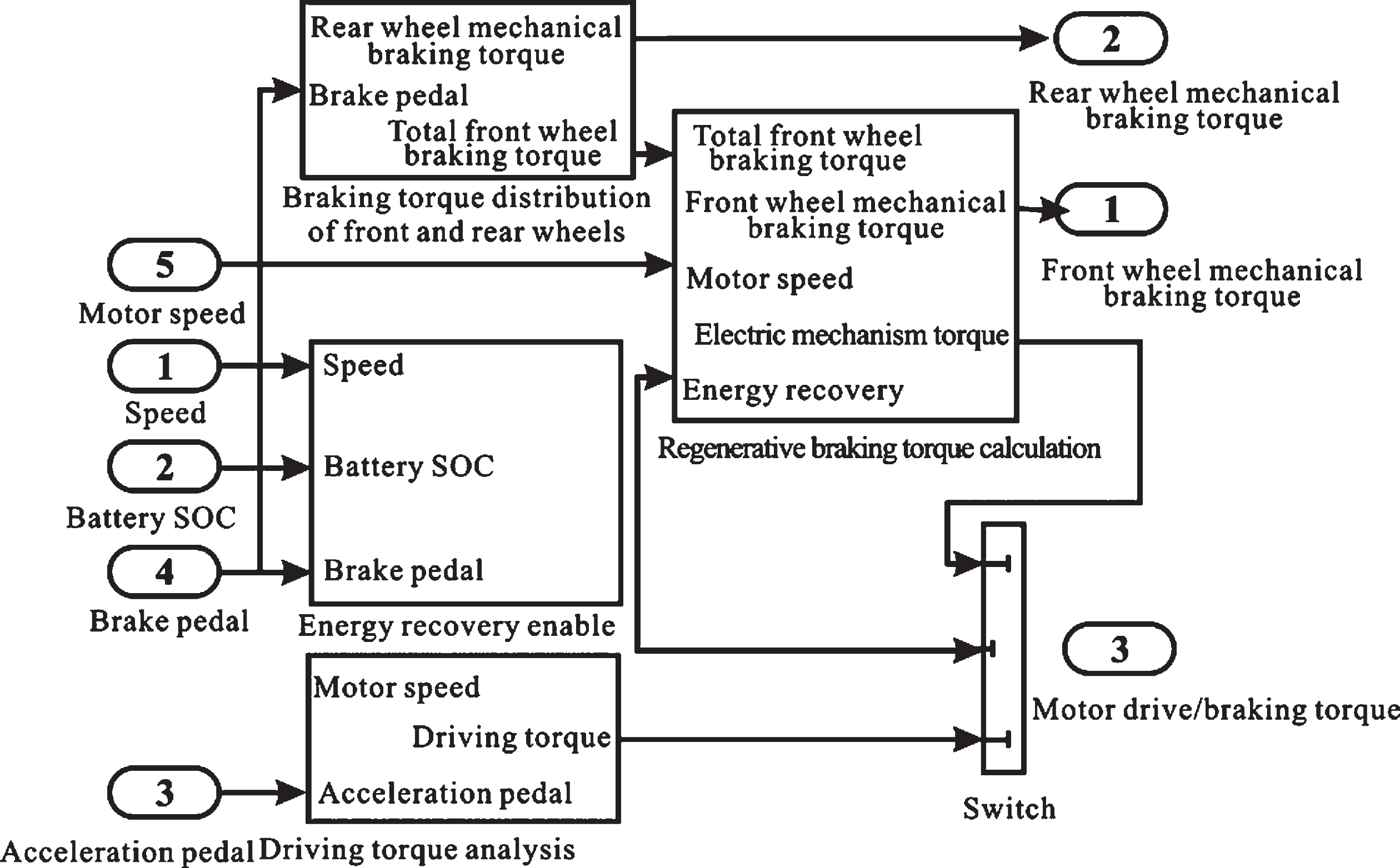
Series regenerative braking model.
With the continuous development of various engine technologies, the electronic control technology of automobiles is developing extremely rapidly and becoming increasingly complex. Therefore, it is necessary to reduce the development time and cost of the control system in the research and development of the automobile electronic control system, which can also accelerate the development process of the engine. Therefore, during the development of automotive electronic control systems, modern electronic development processes are widely used. Development and research are carried out on the basis of the models by modelling, thereby reducing development time and costs. When building a model of control system, it is necessary to build a vehicle model to verify the control strategy. Vehicle control system models are mostly established in Matlab/Simulink. However, many assumptions are often made for the vehicle models based on this platform, some of which can only reflect the changing trend of some engine parameters during the execution of the control strategy. However, when the controller is directly combined with the actual vehicle to run the test, a series of problems often occur, which requires repeated modification of the control strategy and repeated changes of the hardware structure of the controller. This causes a lot of waste of time and cost. At the same time, during the test, because the controller in the development stage is not very complete and stable, it is extremely prone to dangerous accidents, even endangering the lives of testers. If a model that can reflect vehicle performance more comprehensively can be established, the time and cost of control system development can be greatly reduced. GT-SUITE series software is a set of professional vehicle simulation software. The vehicle model established by the GT-Drive module in the software can meet the above requirements. GT-Drive is a multi-purpose vehicle/drive system dynamic analysis tool. It is mainly used in the following areas: Selection and matching of engine+gearbox+vehicle drive system; Simulation calculation of cycle driving conditions, including cycle fuel economy and emissions; Vehicle performance prediction; Simulation of drive system components (such as the layout of clutch, hydraulic torque converter, gearbox, brake, tire, and drive system, etc.); Control of engine and power system.
The hybrid electric vehicle model established by the software can meet the requirements of simulation of engine and power system. Therefore, a joint simulation based on Matlab/Simulink and GT-Drive is carried out on the APU and its control system.
The connection between GT-Drive and Simulink is realized through the control module in GT-Drive, which includes WiringHamess, ActuatorConn (actuator) and SensorConn (sensor). The maximum signal transmission quantity is 64 input signals and 64 output signals. The state parameters of each component of the series hybrid electric vehicle are used as the reference signal of the controller to connect to WiringHamess through SensorConn and transmit to the Simulink model. The output signal of the controller is sent from Simulink to WiringHamess, and controls the controlled object through ActuatorConn.
Because there is no module to control the start and shutdown of the engine in the engine model established in GT-Drive. Therefore, it is set that the engine and the generator are connected through the clutch, and the synchronous operation of the generator and the engine is ensured. In practice, a permanent magnet synchronous generator is selected as the generator. The working characteristics of the generator are consistent with the settings in the model. When the clutch is engaged, the generator and the engine maintain the same speed. When the clutch is activated, the generator will run inertially until it stops. Moreover, the time required for clutch action is ignored in the model, and the opening and closing process for the experimental control of the clutch is consistent with the actual control of the starter motor to start the engine. This can verify whether the controller controls the start and shutdown of the APU effectively. In order to verify the start of the controller, the shutdown function needs to be simulated twice.
The generated current signal is output from In the APU module of the hybrid electric vehicle model, since there is no generator generating voltage. Therefore, it is necessary to perform corresponding calculation processing according to the characteristics, speed, and output power of the generator to obtain the charging current and charging voltage required by the controller.
Based on the new Europe driving cycle (NEDC), Simulink and Cruise are used for joint simulation. The simulation results are shown in Figs. 3 and 4. The current vehicle speed can follow the target vehicle speed well, and the distribution of mechanical braking torque and regenerative braking torque can also meet the requirements of vehicle braking torque, which shows that the simulation model is accurate and reliable.
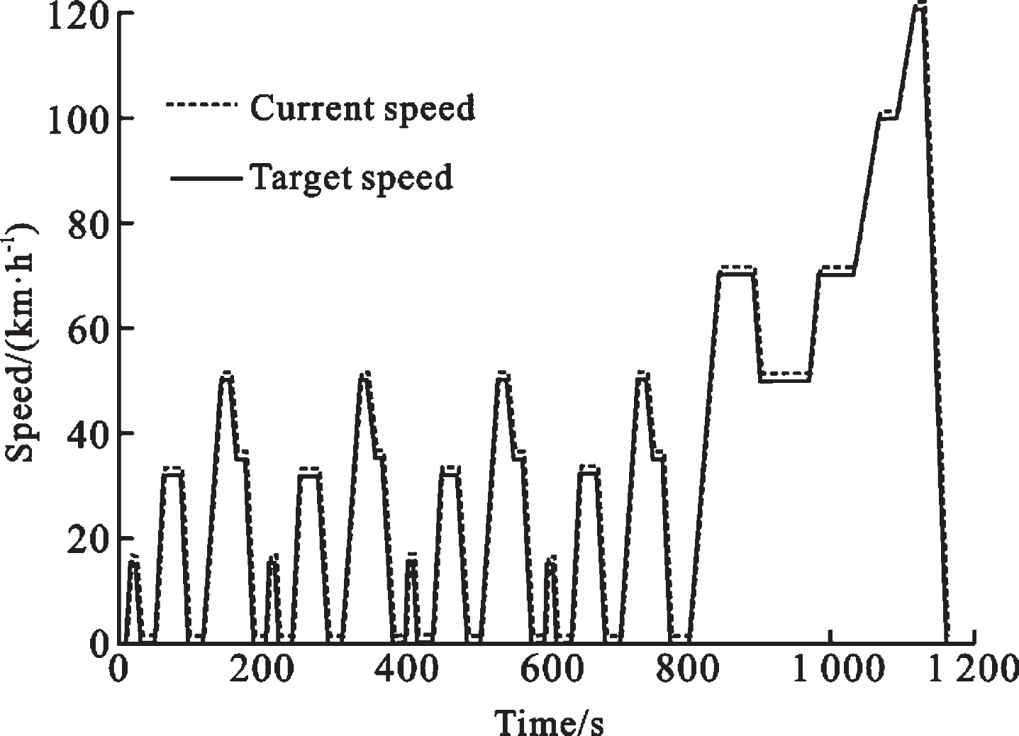
Simulation results of NEDC operating conditions.
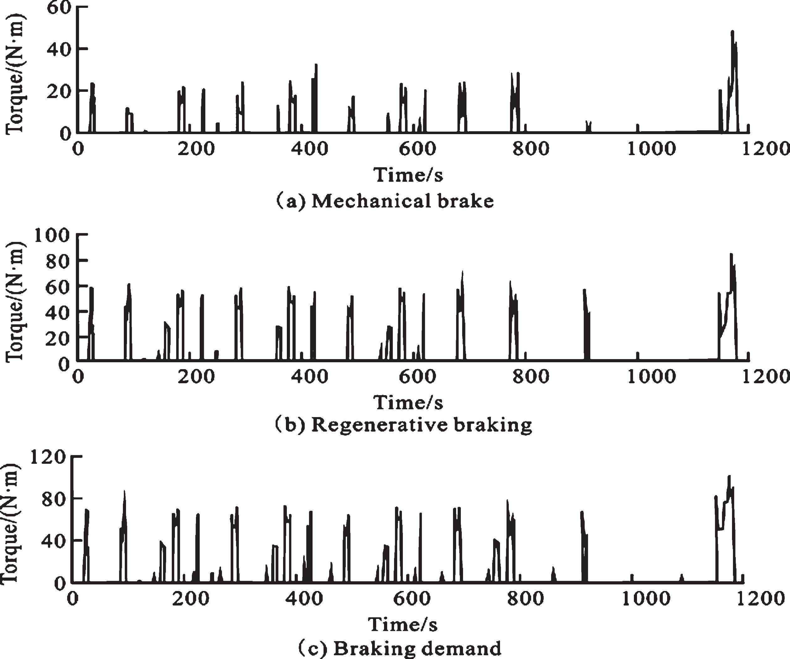
Distribution of braking torque.
It can be seen from Fig. 5 that the curve of state of charge of battery of the series regenerative braking control strategy decreases slowly, with less net energy consumption and more recovery of regenerative braking energy.
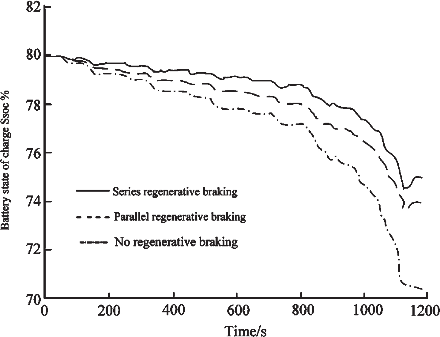
State-of-charge curves of different control strategies.
Integrating the current can get the total input energy and total output energy, the former divided by the latter is the efficiency of the regenerative braking energy recovery. It can be seen from Table 2 that when the series regenerative braking control strategy is adopted, the energy recovery efficiency reaches 25.21%. Compared with the parallel regenerative braking control strategy, the energy recovery rate is increased by 11.55%.
Energy recovery rate of different control strategies
Based on PMSM fuzzy logic, a series-type regenerative braking control strategy is proposed in this paper. Based on the I curve and ECE regulations, the braking torque of the front and rear wheels is reasonably distributed, and the restrictions on the regenerative braking torque of the vehicle speed, characteristics of the battery and motor are comprehensively considered. At the same time, a simulation model was built based on Cruise and Simulink and a joint simulation analysis was performed. The results showed that the built model was accurate and reliable. The energy recovery rate can be improved effectively and the pure Range of electric vehicles can be extended according to proposed series regenerative braking control strategy on the basis of guaranteeing the braking stability. In addition, the proposed series regenerative braking control strategy has high feasibility, laying a foundation for real vehicle applications, and has theoretical and practical significance for the popularization of pure electric vehicles.